ASSEMBLY & OPERATING INSTRUCTIONS
←
→
Page content transcription
If your browser does not render page correctly, please read the page content below
ASSEMBLY & OPERATING INSTRUCTIONS

Model: 720-0536

                                                                                FOR OUTDOOR USE ONLY
FOR PROPANE GAS USE ONLY
This instructions manual contains important information necessary for the proper assembly and safe use of the appliance.
                 Read and follow all warnings and instructions before assembling and using the appliance
                             Follow all warnings and instructions when using the appliance                          1
                                        Keep this manual for future reference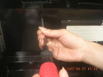
Table of Contents

Safety Instruction . . . . . . . . . . . . . . . . . . . . .    2-7     Gas Conversion . . . . . . . . . . . . . . . . . . . . . .          29-32

Assembly Instruction . . . . . . . . . . . . . . . . . . 8-13           Care and Maintenance . . . . . . . . . . . . . . . . .              33-34

To Match Light the Grill . . . . . . . . . . . . . . . .        14      Oven Maintenance and Cleaning . . . . . . . . .                      35

Gas Hook –Up . . . . . . . . . . . . . . . . . . . . . . . 15-16        Remove the Oven Door . . . . . . . . . . . . . . . .                 36

Installer Final Check List . . . . . . . . . . . . . . .        16      Trouble Shooting . . . . . . . . . . . . . . . . . . . . .          37-40

Leak Testing . . . . . . . . . . . . . . . . . . . . . . . . 17-18      Exploded View . . . . . . . . . . . . . . . . . . . . . . .          41

Operating Instruction . . . . . . . . . . . . . . . . . . 19-21         Part List . . . . . . . . . . . . . . . . . . . . . . . . . . . .   42-43

Grill Lighting Instruction . . . . . . . . . . . . . . . . 21-23        Electrical Wiring Diagram . . . . . . . . . . . . . . .              44

Motor Instruction . . . . . . . . . . . . . . . . . . . . . .   24      Ordering Parts & Grill Hints . . . . . . . . . . . . .               45

Lighting Illustration . . . . . . . . . . . . . . . . . . . . 25-26     Grill Cooking Chart . . . . . . . . . . . . . . . . . . . .         46-48

Converting to Natural Gas . . . . . . . . . . . . . . 26-27             Grill Recipe Suggestion . . . . . . . . . . . . . . . .             49-51

Instruction for Converting to Natural Gas . . .                 28      Limited Warranty . . . . . . . . . . . . . . . . . . . . .           52

                                                                                                                Safety Instruction

                           DANGER                                                               WARNING

If you smell gas:                                                     1. Do not store or use gasoline or other
                                                                      flammable vapors and liquids in the
1. Shut off gas to the appliance.                                     vicinity of this or any other appliance.
2. Extinguish any open flame.
3. Open lid
4. If odor continues, keep away from the                              2. An LP cylinder not connected for use
   appliance and immediately call you                                 shall not be stored in the vicinity of this or
   gas supplier or your fire department.                              any other appliance.

       Failure to comply with these instructions could result in a fire or explosion that could cause serious bodily
       injury, death, or property damage.

        Combustion by products produced when using this product contain chemicals known to the States of
        California to cause cancer, birth defects, or other reproductive harm

        Your grill will be very hot. Never lean over the cooking area while using your grill. Do not touch cooking
        surfaces, grill housing. Lid or any other grill parts while the grill is in operation, or until the gas grill has
        cooled down after use.
                                                                                                                                             2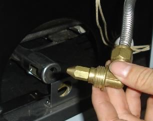
Safety Instruction

           WARNING

ELECTRICAL GROUNDING INSTRUCTIONS This appliance (rotisserie motor) is equipped with a plug
and should be plugged directly into a properly grounded receptacle. When installed, must be electrically grounded
in accordance with local codes or in the absence of local codes, with the National Electrical Code, ANSI/NFPA 70
or the Canadian Electrical Code, CSA C22.1 DO NOT cut or remove the grounding prong from this plug.

 1.    To protect against electric shock, do not immerse cord or plugs in water or other liquid.
 2.    Unplug from the outlet when not in use and before cleaning. Allow to cool before putting on or taking off
       parts.
 3.    Do not operate any outdoor cooking gas appliance with a damaged cord, plug, or after the appliance
       malfunctions or has been damaged in any manner. Contact the manufacturer for repair.
 4.    Do not let the cord hang over the edge of a table of touch hot surface.
 5.    Do not use an outdoor cooking gas appliance for purposed other than intended.
 6.    When connecting, first connect plug to the outdoor cooking gas appliance then plug appliance into the outlet.
 7.    Use only a Ground Fault Interrupt (GFI) protected circuit with this outdoor cooking gas appliance.
 8.    Never remove the grounding plug or use with an adapter of 2 prongs.
 9.    Use only extension cords with a 3 prong grounding plug, rated for the power of the equipments, and
       approved for outdoor use with a W-A marking.

                                                                                                            3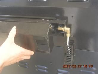
Safety Instruction

                       WARNING                                    CAUTION: Beware of Flashback
Do not try lighting this appliance without reading the        CAUTION: Spiders and small insects occasionally
“LIGHTING INSTRUCTIONS” section of this manual.                spin webs or make nest in the grill
                                                              burner tubes during transit and
                                                              warehousing. These webs can lead
TESTED IN ACCORDANCE WITH ANS                                  to gas flow obstruction, which could
Z21.58 CSA 1.6-2007 STANDARD FOR                               result in a fire in and around burner
OUTDOOR COOKING GAS APPLIANCE.                                 tubes. This type of fire is known as
                                                               “FLASH-BACK” and can cause serious damage to
THIS GRIL IS FOR OUTDOOR USE ONLY.                            your grill and create an unsafe operating condition for
                                                              the user.

                                                              Although an obstructed burner tube is not the only
Grill Installation Codes                                      cause of “FLASH-BACK”, it is the most common
Check your local building codes for the proper method of      cause.
installation. in the absence of local codes, this unit
should be installed in accordance with the National Fuel      To reduce the chance of “FLASH-BACK”, you must
Gas Code ,ANSI Z223.1/NFPA 54,Storage and Handling            clean the burner tubes before assembling your grill,
of Liquefied Petroleum Gases, ANSI /NFPA B149.2 or            and at least once a month in late summer or early fall
CSA B149.1 Natural Gas and Propane Installation Code,         when spiders are most active. Also perform this
and the National Electrical Code, ANSI/NFPA 70.               burner tube cleaning procedure if your grill has not
Correct LP Gas Tank Use                                       been used for an extended period of time. A clogged
LP gas grill models are designed for use with a standard      tube can be lead to a fire beneath the grill.
20 lb. Liquid Propane Gas tank, not included with grill.
Never connect your gas grill to an LP gas tank that
exceeds this capacity.

If an external electrical source is utilized: The outdoor
cooking gas appliance, when installed, must be
electrically grounded in accordance with local codes or,
in the absence of local codes, with the National Electrical
Code, ANSI/NFPA 70, or the Canadian Electrical Code,
CSA C22.1.

WARNING
Keep any electrical supply cord and the fuel supply hose
away from any heated surfaces.                                 Visually check the burner flames prior to each use,
                                                                the flames should look like this picture, if they do not,
                                                               refer to the burner main tenancy part of this manual.

NOTE: The normal flow of gas through the regulator and
hose assembly can create a humming noise. A low
volume of noise is perfectly normal and will not interfere
with operation of the grill. If humming noise is loud and
excessive you may need to purge air from the gas line or
reset the regulator excess gas flow device. This purging
procedure should be done every time a new LP gas tank
is connected to your grill.

                                                                                                                            4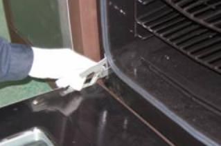
Safety Instruction

LP-Gas Supply System

                                                                         PROPER PLACEMENT AND CLEARANCE OF
§A 20lb tank of approximately 1/4 inches in diameter by 18-1/4
inches high is the maximum size LP gas tank to use.                      GRILL
§This safety feature prevents the tank from being overfilled, which
can cause malfunction of the LP gas tank, regulator and/or grill.        •Never use your gas grill in a garage, porch, shed,
§The LP gas supply cylinder to be used must be constructed and           breezeway or any other enclosed area. Your gas grill is
marked in accordance with the specifications for LP –Gas cylinder of     to be used outdoors only.
the U.S. Department of Transportation (DOT) or the National              •Do Not install this unit into combustible enclosures.
Standard of Canada ,CAN/CSA –B339, Cylinders, Spheres and                •Minimum clearance from sides and back of unit to
Tubes for Transportation of Dangerous Goods and Commission .             combustible construction, 24 inches (61cm) from sides
§The LP gas tank must have a shutoff valve terminating in an LP          and 24 inches (61cm) from back.
valve outlet that is compatible with a Type 1. LP gas supply cylinder    •DO NOT uses this appliance under overhead
must have a shut off valve terminating in a valve outlet specified for   combustible surfaces. This outdoors cooking gas
connection type QCC1 in the standard for compressed gas cylinder         appliance is not intended to be install in or on
valve outlet and inlet connection ANSI/CGA-V-1 as applicable. LP         recreational vehicles and/or boats.
gas supply cylinder must be fitted with an Overfill Protection Device    •Do Not obstruct the flow of ventilation air around the
(O.P.D) The LP gas tank must also have a safety relief device that       gas grill housing. Only use the regulator and the hose
has a direct connection with the vapor space of the tank.                assembly supplied with your gas grill. Replacement
§The tank supply system must be arranged for vapor withdrawal.           regulators and hose assemblies must be those specified
§The LP gas tank used must have a collar to protect the tank valve       in this manual.
§Place dust cap on cylinder valve outlet whenever the cylinder is not    •The regulator and hose assembly must be inspected
in use. Only install the type of dust cap on the cylinder valve outlet   before each use of the grill. If there is excessive
that is provided with the cylinder valve. Other types of cap or plugs    abrasion or wear or if the hose is cut, it must be
may result in leakage of propane                                         replaced prior to the grill being put into operation. The
§Never connect an unregulated LP gas tank to your gas grill.             replacement hose assembly shall be that specified by
§This outdoor cooking gas appliance is equipped with a high capacity     the manufacturer.
hose/regulator assembly for connection to a standard 20lb. Liquid        •Pressure regulator and hose assembly supplied with
propane cylinder.                                                        the outdoor cooking gas appliance must be used. Never
§Have your LP gas tank filled by a reputable propane gas                 substitute other types of regulator. Contact customer
dealer and visually inspected and re-qualified at each filling.          service for manufacturer specified replacement parts.
§Do not store a spare LP gas cylinder under or near this                 •This outdoor cooking gas appliance is equipped with a
appliance.                                                               pressure regulator comply with the standard for
§Never fill the cylinder beyond 80 percent full .                        Pressure Regulating Valves for LP Gas ANSI/ UL 144.
 §If the informations not followed exactly, a fire resulting in          •Do not use briquettes of any kind in the grill.
 death or serious injury could occur.                                    •The grill is designed for optimum performance without
§Always keep LP gas tanks in an upright position.                        the use of briquettes. Do not place briquettes on the
§Do not store or use gasoline or other flammable vapors and liquids      radiant as this will block off the area for the grill burners
in the vicinity of this or any other appliance.                          to vent. Adding briquettes can damage ignition
§Storage of an outdoor cooking gas appliance indoors is permissible      components and knobs, and void the warranty.
only if the cylinder is disconnected and removed from the outdoor        •Keep the back and side cart free and clear from debris.
cooking gas appliance..                                                  Keep any electrical supply cord, or the rotisserie motor
§When your gas grill is not in use the gas must be turned off at LP      cord away from the heated areas of the grill.
gas tank.                                                                •Never use the grill in extremely windy conditions. If
•The gas must be turned off at the supply cylinder when the outdoor      located in a consistently windy area (oceanfront,
cooking gas appliance is not in use.                                     mountaintop, etc.) a windbreak will be required. Always
•LP gas tank must be stored outdoors in a well-ventilated area and       adhere to the specified clearance.
out of reach of children. Disconnected LP gas tanks must not be          •Never use a dented or rusty propane tank.
stored in a building. Garage or any other enclosed area.                 •Keep any electrical supply cord and the fuel supply
                                                                         hose away from any heated surface
                                                                         •While lighting, keep your face and hands as far away
                                                                         from the grill as possible.
                                                                         •Burner adjustment should only be performed after the
                                                                         burner have cooled.

                                                                                                                             5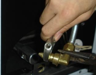
Safety Instruction

                       WARNING                              SAFETY PRACTICES TO AVOID PERSONAL

Your grill will get very hot. Never lean over the           INJURY
cooking area while using your grill. Do not touch
cooking surfaces, grill housing, lid or any other grill     When properly cared for, your grill will provide safe,
hot surface while the grill is in operation, or until the   reliable service for many years. However, extreme
gas grill has cooled down after use.                        care must be used as the grill produces intense heat
                                                            that can increase accident potential. When using
Failure to comply with these instructions may               this appliance basic safety practices must be
result in serious bodily injury.                            followed, including the following:
ROTISSERIE DRIVE MOTOR
                                                            Do not repair or replace any part of the grill unless
USE ONLY FOR OUTDOORS, DO NOT EXPOSE
                                                            specifically recommended in this manual. All other
TO RAIN.
                                                            service should be referred to a qualified technician.
CAUTION: TO ENSURE CONTINUED                                This grill is not intended to be installed in or on
PROTECTION AGAINST RISK OF ELECTRIC                         recreational vehicles or boats
SHOCK, CONNECT TO PROPERLY GROUNDED
OUTLETS ONLY, TO REDUCE THE RISK OF
ELECTRIC SHOCK, KEEP EXTENSION CORD                         Children should not be left alone or unattended in an
CONNECTION DRY AND OFF THE GROUND.                          area where the grill is being used. Do not allow them
                                                            to sit, stand or play in or around the grill at any time.
                                                            Do not store items of interest to children around or
                 INSECT WARNING:
                                                            below the grill.
Spiders and insects can nest in the burners of this
and any other grill, and cause the gas to flow              Do not permit clothing, pot holders or other
improperly. This is a very dangerous condition, which       flammable materials to come in contact with or too
can cause a fire to occur behind and beneath the            close to any grate, burner or hot surface until it has
valve panel, thereby damaging the grill and making it       cooled. The fabric could ignite and cause
unsafe to operate. Inspect the grill twice a year.
                                                            personal injury .
                                                            For personal safety, wear proper apparel. Loose
                       WARNING                              fitting garments or sleeves should never be worn
                                                            while using this appliance. Some synthetic fabrics
Keep a spray bottle of soapy water near the gas             are highly flammable and should not be worn while
supply valve and check the connections before each          cooking.
use.
                                                            Only certain types of glass, heat-proof glass
DO NOT USE ALUMINUM FOIL TO LINE THE                        ceramic, earthenware, or other glazed utensils are
GRILL RACKS OR GRILL BOTTOM.                                suitable for grill use. These materials may break
This can severely upset combustion airflow or trap          with sudden temperature changes. Use only on low
excessive heat in the control area.                         or medium heat settings in accordance with the
                                                            manufacturer’s guidelines.
DO NOT LEAVE THE GRILL UNATTENDED
WHILE COOKING.

                                                                                                             6
Safety Instruction

Do not heat unopened food containers. A build-up of
                                                             Do not use the grill to cook excessively fatty meats or
pressure may cause the containers to burst.
                                                             other products which promote flare – ups.
Use a covered hand when opening the grill lid.
                                                             Do not operate the grill under unprotected combustible
                                                             constructions. Use only in well ventilated areas. Do
Never lean over an open grill.
                                                             not use in buildings, garages, sheds, breezeways or
                                                             other such enclosed areas.
When lighting a burner, pay close attention to what
you are doing. Make certain you are aware of which
                                                             Keep the area surrounding the grill free from
burner you are lighting, so your body and clothing
                                                             combustible materials including, fluids, trash, and
remain clear of open flames.
                                                             vapors such as gasoline or charcoal lighter fluid. Do
                                                             not obstruct the flow of combustion and ventilation air.
When using the grill, do not touch the grill rack, burner
grate or immediate surroundings as these areas
become extremely hot and could cause burns. Use
only dry potholders. Moist or damp potholders on hot                      WARNING
surfaces may cause steam burns. Do not use a towel
or bulky cloth in place or potholders. Do not allow
potholders to touch hot portions of the grill rack.              This outdoor cooking gas appliance is not
                                                                intended to be installed in or on boats. For
Grease is flammable. Let hot grease cool before                 other than RV grills, a statement that this
attempting to handle it. Do not allow grease deposits           appliance is not intended to be installed in or
to collect in the grease tray at the bottom of the grill’s
                                                                on recreational vehicles.
firebox. Clean the grease tray often.

Do not use aluminum foil to line the grill racks or grill
bottom. This can severely upset combustion air flow or
trap excessive heat in the control area.

For proper lighting and performance of the burners
keep the burner ports clean. It is necessary to clean
them periodically for optimum performance. The
burners will only operate in one position and must be
mounted correctly for safe operation.

Clean the grill with caution. To avoid steam burns, do
not use a wet sponge or cloth to clean the grill while it
is hot. Some cleaners produce toxic fumes or can
ignite if applied to a hot surface.

Turn off grill controls and make certain the grill is cool
before using any type of aerosol cleaner on or around
the grill. The chemical that produces the spraying
action could, in the presence of heat, ignite or cause
metal parts to corrode.

                                                                                                               7
Assembly Instruction
PLEASE READ THESE INSTRUCTIONS CAREFULLY AND FOLLOW STEP BY STEP
► Propane Tank sold separately
► Tools required, Phillips head screwdriver and 10 wrench. (not included)
► All screws packed in the hardware pack, totally 20 screws in it.
STEP 1: Remove screws from hardware packet, attach the side shelf to the side shelf control panel
with 4 screws for each side as shown below. There are 8 screws for two sides.
8Assembly Instruction Continued
STEP 2: Remove screws from hardware packet, attach the side shelf push bar to the right side shelf
from inside to outside as shown below. There are 2 screws for push bar.
9Assembly Instruction Continued
STEP 3. Assemble the side shelf and side control panel into the firebox with eight screws as shown
below.
Attention: the upper 2 screws to the firebox should be screwed from inside to outside for right side
shelf , but the other screws should be firmed from outside into inside.
Meanwhile assemble the side shelf control panel and main control panel with 2 screws for both
sides.
10Assembly Instruction Continued
STEP 4: Battery is inserted for the Rotisserie burner and searing burner. To install the battery,
turn the ignition button cap counterclockwise and remove it. Replace the ignition button cap after
the battery is installed.
Instruct to remove batteries if consumed or if product is to be left unused for a long time.
11Assembly Instruction Continued
STEP 5: Attach propane gas tank to regulator inlet fitting by turning the regulator clockwise
as shown in figure below. LP gas cylinder must be fitted with a listed overfill prevention
device (OPD). Open the door and pull out the tray, place the gas tank cylinder in the tank
tray , then use retention kit that showed as below diagram to secure the tank cylinder . Make
sure tank is level in the tank tray for proper vapor withdrawal.
CYLINDER TANK FIXED
12Assembly Instruction Continued
STEP 6: The screws for rotisserie drive motor bracket are screwed into the right side of the grill
housing. Remove the screws and install the rotisserie motor bracket as shown in the figure below.
Assemble the rotisserie skewer as shown in the figure below.
13To Match Light the Grill
1. If the burner will not light after several attempts then the burner can be match lit.
2. If you have attempted to light the main burners with the igniter, allow 5 minutes for
any accumulated gas to dissipate.
3. Insert a match into the lighting rod. Ignite the match and insert through the cooking
grid to the burner.
4. Press the control knob and rotate it to the “Ignite/HI” setting. The burner should
light immediately.
5. If the burner does not light within seconds turn the knob to the “OFF” position, wait
5 minutes and try again. (as shown below)
14Gas Hook - Up
NEVER CONNECT AN UNREGULATED GAS QCC1 in the standard for compressed gas
SUPPLY LINE TO THE APPLIANCE. USE cylinder valve outlet and inlet connection
THE REGULATOR/HOSE ASSEMBLY ANSI/CGA-V-1.
SUPPLIED.
Manifold pressure: 11”(27.94cm) water
This is a liquid propane configured grill. Do not column (W.C.).
attempt to use a natural gas supply unless the
L.P. GAS HOOK-UP
grill has been reconfigured for natural gas use.
Ensure that the black plastic grommets on the
Total gas consumption (per hour) of this
LP cylinder valve are in place and that the
stainless steel gas grill with all burners on “HI”:
hose does not come into contact with the
grease tray or the grill head.
Main burner 40,000 Btu/hr. CONNECTION
Rear burner 13,000 Btu/hr.
Your stainless steel grill is equipped with gas
Side burner 12,000 Btu/hr. supply orifices for use only with liquid
Sear burner 18,000 Btu/hr. propane gas. It is also equipped with a high
oven 16,000 Btu/hr. capacity hose/regulator assembly for
Total 99,000 Btu/hr. connection to a standard 20lb. L.P. cylinder
(18-1/4” (46.35cm) high, 12-1/4”(31cm)
diameter). To connect the L.P. gas supply
L.P. TANK REQUIREMENT
cylinder, please follow the steps below:
A dented or rusty L.P. tank may be hazardous 1. Make sure tank valve is in its full off
and should be checked by your L.P. supplier. position (turn clockwise to stop)
Never use a cylinder with a damaged valve. 2. Check tank valve to assure it has proper
The L.P. gas cylinder must be constructed and external male threads (type 1 connection
marked in accordance with the specifications per ANSIZ21.81)
for L.P. gas cylinders of the U.S. Department
of Transportation (DOT) or the National
Standard of Canada, CAN/CSA-B339,
Cylinders, Spheres and Tubes for
Transportation of Dangerous Goods; and
Commission, as applicable. Overfilling
prevention device (OPD) shall be provided on
cylinder & QCCI connection on the cylinder 3. Make sure all burner valves are in their off
valve, ANSI/CGA-V-1. The cylinder supply position.
system must be arrange for vapor withdrawal. 4. Inspect valve connections, port, and
The cylinder must include a collar to protect regulator assembly. Look for any damage
the cylinder valve. The cylinder must be or debris. Remove any debris. Inspect
provided with a shut off valve terminating in an hose for damage. Never attempt to use
L.P. gas supply cylinder valve outlet specified, damaged or obstructed equipment. See
as applicable, for connection type your local L.P. gas dealer for repair. 15Gas Hook - Up
5. When connecting regulator assembly to the 7. If you have a gas connection leak you
valve, hand tighten the quick coupling nut cannot repair, turn gas OFF at supply tank,
clockwise to a complete stop. Do not use a disconnect fuel line from your grill and call
wrench to tighten. Use of a wrench may 1-800-648-5864 or your gas supplier for
damage the quick coupling nut and result in repair assistance.
a hazardous condition.
8. Also apply soapy solution to the tank
6. Open the tank valve fully (counterclockwise). seams. See below. If growing bubbles
Apply the soap solution with a clean brush appear, shut tank OFF and do not use or
to all gas connections. See below. If move it! Contact an LP gas supplier or
growing bubbles appear in the solution the your fire department for assistance
connections are not properly sealed. Check
each fitting and tighten or repair as
necessary.
To disconnect L.P. gas cylinder:
1. Turn the burner valves off.
2. Turn the tank valve off fully (turn
clockwise to stop).
3. Detach the regulator assembly from the
tank valve by turning the quick coupling
nut counterclockwise.
Installer Final Check List
ü Specified clearance maintained PROPANE CYLINDER CAUTIONS
24”(61cm) from combustibles.
ü All internal packaging removed. a) Do Not store a spare LP-gas cylinder
ü Knobs turn freely. under or near this appliance.
ü Burners are tight and sitting properly on b) NEVER fill the cylinder beyond 80
orifices. percent full.
ü Pressure regulator connected and set.
Gas connections to grill using hose & c) If the information in “a” and “b” is not
regulator assembly provided (pre-set for followed exactly, a fire causing death
11.0” water column).
or serious injury may occur.
ü Unit tested and free of leaks.
ü User informed of gas supply shut off
valve location
USER, PLEASE RETAIN THIS MANUAL
FOR FUTURE REFERENCE. 16Leak Testing
GENERAL Only those parts recommended by the
Although all gas connections on the grill are leak manufacturer should be used on the grill.
tested at the factory prior to shipment, a complete
Substitution will void the warranty. Do not use
gas tightness check must be performed at the
the grill until all connections have been checked
installation site due to possible mishandling in
shipment, or excessive pressure unknowingly and do not leak.
being applied to the unit. Periodically check the GAS FLOW CHECK
whole system for leaks following the procedures
listed below. If the smell of gas is detected at Each grill burner is tested and adjusted at the
anytime you should immediately check the entire factory prior to shipment; however, variations in
system for leaks. the local gas supply may make it necessary to
adjust the burners. The flames of the burners
BEFORE TESTING should be visually checked.
Make sure that all packing material is removed Flames should be blue and stable with no yellow
from the grill including the burner tie-down straps. tips, excessive noise or lifting. If any of these
DO NOT SMOKE WHILE LEAK TESTING. conditions exist, check to see if the air shutter or
burner ports are blocked by dirt, debris, spider
NEVER PERFORM LEAK TEST WITH AN OPEN webs, etc. If you have any questions regarding
FLAME. flame stability, please call customer service
Make a soap solution of one part liquid detergent 1-800-648-5864 .
and one part water. You will need a spray bottle,
brush, or rag to apply the solution to the fittings. ALWAYS CHECK FOR LEAKS AFTER
For the initial leak test, make sure the L.P. cylinder EVERY L.P. TANK CHANGE
is full.
Check all gas supply fittings for leaks
TO TEST before each use. It is handy to keep a
1. Make sure the control valves are in the “OFF” spray bottle of soapy water near the shut-
position, and turn on the gas supply. off valve of the gas supply line. Spray all
2. Check all connections from the LP gas regulator the fittings. Bubbles indicate leaks.
and supply valve up to and including the
connection to the manifold pipe assembly (the pipe
that goes to the burners). Soap bubbles will appear
where a leak is present.
3. If a leak is present, immediately turn off the gas
supply and tighten the leaky fittings.
4. Turn the gas back on and recheck.
5. Should the gas continue to leak from any of the
fittings, turn off the gas supply and contact
customer service at 1-800-648-5864.
17CAUTIONS
Place dust cap on cylinder valve outlet when the cylinder is not in use. Only install the
type of dust cap on the cylinder valve outlet that is provided with the cylinder valve.
Other types of caps or plugs may result in leakage of propane.
The gas must be turned off at the supply cylinder when the unit is not in use.
If the appliance is stored indoors the cylinder must be disconnected and removed from
the appliance. Cylinders must be stored outdoors in a well-ventilated area out of the
reach of children.
Your grill is ready to use!
18Operating Instructions
GENERAL USE OF THE GRILL AND WARNING: IMPORTANT!
ROTISSERIE
USING THE SIDE BURNER:
Each main burner is rated at 10,000 Btu/hr.
The main grill burners encompass the entire Inspect the gas supply hose prior to turning
cooking area and are side ported to the gas “ON”. If there is evidence of cuts,
minimize blockage from falling grease and wear or abrasion, it must be replaced prior
debris. Above the burners are porcelain to use. Do not use the side burner if the odor
coated steel radiant (flame tamer). The of gas is present.
igniter knobs are located on the lower center
portion of the valve panel. Each rotary USING ROTISSERIE BURNER
igniter is labeled on the control panel. Your grill is capable of performing back
USING THE GRILL burner rotisserie cooking. Light the rear
burner as described in the lighting instructions,
Grilling requires high heat for searing and see page 25-26. Once lit, the rotisserie burner
proper browning. Most foods are cooked at will reach cooking temperatures in about 1
the “HI” heat setting for the entire cooking minute.
time. However, when grilling large pieces of
meat or poultry, it may be necessary to turn
the heat to the lower setting after the initial
browning. This cooks the food through
without burning the outside. Foods cooked
for a long time or foods basted with a sugary
marinade may need the lower heat setting
near the end of the cooking time.
NOTE: This stainless steel grill is designed
to grill efficiently without the use of lava
rocks or briquettes of any kind. Heat is
radiated by the stainless steel flame tamers
positioned above each burner.
NOTE: The hot grill sears the food, sealing
in the juices. The longer the preheat, the
faster the meat browns and the darker the
grill marks.
DO NOT LEAVE THE GRILL
UNATTENDED WHILE COOKING.
19Operating Instructions Continued
USING THE OVEN
OVEN VENT:
Do not block the ducts at the rear of the range when cooking in the oven. It is important that the flow of hot air from
the oven and fresh air into the oven burner never be interrupted. Avoid touching the vent openings or nearby surfaces
during oven or broiler operation – they may become hot.
PLUG-IN:
The electric cord attached to the back of the grill must be plugged in to a 120V A/C outlet so the oven will operate.
The oven is equipped with a hot surface igniter that turns the burner on & off as necessary. Please note that when
the hot surface igniter is on, the indicator light on the control panel is also on. When the hot surface igniter turns off,
gas flowing to the burner stops & the indicator light turns off.
OVEN THERMOSTAT:
The oven is thermostatically controlled to maintain even cooking temperature. Simply set the control knob to the
desired temperature & the thermostat will turn the oven on & off as necessary.
RACK BAKING:
Many foods, such as pizzas, cakes, muffins, rolls, and cookies can be successfully prepared using two racks at the
Same time.
NATURAL AIRFLOW BAKE:
Heat is transferred into the oven from the oven burner in the bottom of the oven cavity. Heat is then circulated by
natural airflow. This is a traditional bake setting.
THE OVEN LIGHT:
Oven is equipped with a 25V Halogen light which is turned on or off by the switch on the control panel.
Rack position 5 (highest position): For toasting bread or broiling thin, non-fatty foods.
Rack position 3:and 4 Used for most baked goods on a cookie sheet or jellyroll pan, layer cakes, fruit pies,
or frozen convenience foods.
Rack position 2: Used for roasting small cuts of meat, baking loaves of bread, cakes or pies.
Rack position 1: Used for roasting large cuts of meat and poultry, frozen pies, dessert soufflés, or
angel food cake.
Multiple racks Cooking: Two Racks Use rack 2 and 4, or rack position 1 and 4.
Caution: Your oven does not operate when electrical power failure occurs
(5)
(4)
(3)
(2)
(1)
20Operating Instructions Continued
CAUTION: PLEASE TAKE OFF THE
WARMING RACK WHEN USING THE
ROTISSERIE BURNER. THE HIGH HEAT
COMING FROM THE ROTISSERIE
BURNER MAY CAUSE THE WARMING
RACK TO BEND.
Grill Lighting Instructions
WARNING: IMPORTANT! Never substitute regulators and hose
BEFORE LIGHTING… assembly for those supplied with the grill. If
a replacement is necessary, contact the
Inspect the gas supply hose prior to turning manufacturer for proper replacement. The
the gas “ON”. If there is evidence of cuts, replacement must be that specified in the
wear, or abrasion, it must be replaced prior manual.
to use. Do not use the grill if the odor of gas
is present. Only the pressure regulator and Screw the regulator (type QCC1) onto the
hose assembly supplied with the unit should tank. Leak check the hose and regulator
be used. connections with a soap and water solution
before operating the grill.
21Grill Lighting Instructions continued
TO LIGHT THE GRILL BURNER: If you’ve just attempted to light the burner
with the igniter, allow 5 minutes for any
Make sure all knobs are “OFF” then turn on
accumulated gas to dissipate. Keep your face
the gas supply from the LP tank. Always keep
and hands as far away from the grill as
your face and body as far from the grill as
possible. Insert a lit match attached to lighting
possible when lighting.
rod or lighter through the cooking grids to the
Your stainless steel grill has an exclusive burner.(see next page) Press the control knob
patented built-in ignition. The igniter is built in and rotate left to the IGNITE/HI setting,
to the valve. To ignite each burner simply continue to press the knob until the burner
push and turn the control knobs to the HI ignites. Burner should light immediately. If the
setting, you will hear the valve click as it burner does not light in 4 seconds turn the
sends a spark to the pilot flame. If the burner knob off, wait 5 minutes and try again.
does not light wait 5 minutes for any excess
gas to dissipate and then retry.
TO MATCH LIGHT THE SIDE BURNER
WARNING: Always keep your face and body
as far away from the burner as possible when Hold a lit extended match or lighter near the
lighting. side burner ports, turn the control knob
TO LIGHT THE SIDE BURNER counterclockwise to “IGNITE/HI”. Move your
hand immediately once the burner is lit.
To light the side burner, remove any cooking Rotate the control knob to the desired
utensils from the burner grate. Push and turn setting.
the control knob counterclockwise to the
“IGNITE/HI” position. If the burner does not TO LIGHT THE OVEN BURNER:
light, turn the control Push the control knob & rotate it counter-
clockwise to the desired temperature. You will
knob to “OFF”. If the smell of gas is detected hear click when turning the knob. This click
and the igniter is not functioning, indicates that the igniter is turned on. Gas will
immediately turn the control knob “OFF”. begin to flow & the burner will light when the
Allow 5 minutes for any accumulated gas to igniter has reached the proper temperature.
dissipate. If the side burner igniter is not This process will take 35-50 seconds. When
functioning, see the following section for turning the knob, you will notice the click & the
match lighting. indicator light will be illuminated. This indicates
TO MATCH LIGHT THE GRILL the igniter is turned on & the gas will start to
flow.
If the burner will not light after several attempts
then the burner can be match lit.
Keep a spray bottle of soapy water near
1. Locate match light extension rod the gas supply valve and check the
connections before each use.
2. Use this device to match light your burners
Simply place a lighted match between the coils
on the end of the extension rod and hold next to Do not attempt to light the grill if odor of
the burner to ignite. gas is present. Call for service 1-800-648-
5864 22
22Grill Lighting Instructions continued
FLAME CHARACTERISTICS
Check for proper burner flame characteristics. Each burner is adjusted prior to
shipment; however, variations in the
Burner flames should be blue and stable with
local gas supply may take minor
no yellow tips, excessive noise, or lifting. If
adjustments necessary.
any of these conditions exist call our
customer service line. If the flame is yellow, it
indicates insufficient air. If the flame is noisy
And tends to lift away from the burner, it
Indicates to much air.
Visually check the burner flames prior to
each use,The flames should look like this
picture,if they do not ,refer to the
burner maintenance part of this manual
Approximate 1 1/2 “ Flame Height
23Motor Instruction
• TO USE MOTOR SAFELY, PLEASE READ WARNING PRIOR TO USE
ROTISSERIE DRIVE MOTOR
USE ONLY FOR OUTDOORS. DO NOT EXPOSE TO RAIN.
CAUTION: TO ENSURE CONTINUED PROTECTION AGAINST RISK OF ELECTRIC SHOCK,
CONNECT TO PROPERLY GROUNDED OUTLETS ONLY, TO REDUCE THE RISK OF ELECTRIC
SHOCK, KEEP EXTENSION CORD CONNECTION DRY AND OFF THE GROUND.
WARNING
ELECTRICAL GROUNDING INSTRUCTIONS This appliance (rotisserie motor) is equipped with a
plug and should be plugged directly into a properly grounded receptacle. DO NOT cut or remove
the grounding prong from this plug.
Keep the rotisserie motor electric cord away from the heated surfaces of the grill. When not in use remove
and store the motor in a dry location.
This motor is set for 120V AC & 60Hz, 3.2W, 40mA, If voltage is exceeded, motor will be burn out.
Rotisserie Operating illustrations:
1. Place rotisserie motor onto the motor bracket, plug into a properly grounded outlet. Ensure
that the rotisserie spit rod is inserted into the motor prior to turning on the motor.
Insert rotisserie spit rod 120V AC 60Hz, 3.2W, 40mA
2. When finished using rotisserie motor, switch to “off” position and unplug.
24Lighting Illustration
Main & Side Burner Lighting Illustration Rotisserie Burner or Searing Burner
Lighting Illustration
Step 1.
Step to light the Rotisserie Burner :
Make sure the Lid is open
push electronic ignition button then
push and turn the rotisserie knob to
“ON” position , until burner is lit.
Step 2.
Push and turn main or side burner knobs to “HI”
position. Pilot torch will light. Hold for 3-4 seconds until
burner is lit.
Step to light the Searing Burner:
push electronic ignition button then
push and turn the Searing knob to
“ON” position , until burner is lit.
Step 3.
You may need to try 3 or 4 times to light the burner.
After the burner is lit, adjust the knob as desired.
25Lighting Illustration Continued
Step 1.Push & Turn the Knob to light the oven Step 2.After the burner is lit, adjust the
Burner, it may take about 36-50 seconds to light temperature
the Oven burner as you need
Converting to Natural Gas
This Grill is portable and configured for use with Liquid Propane (LP Gas), which is
delivered to the grill from removable tanks (LP tanks and their use are covered elsewhere in this
manual). If a Natural Gas connection is available, the user may wish to change the gas delivery
system to the more permanent Natural Gas supply.
This grill is certified for use with either Liquid Propane (LP Gas) or Natural Gas and
comes complete with the necessary parts to convert it for use with Natural Gas. The Nexgrill
patented Conversion Valves allows the use of Natural Gas without replacing the burners or
entire valve system.
Additional parts needed are a Natural Gas Supply Hose and Regulator Valve (if
necessary).
The process of converting is relatively simple and can be accomplished by any handy
homeowner. Nexgrill suggests, however, that a qualified gas technician do the conversion.
Your warranty may be voided if the conversion is improperly completed. Please retain the parts
supplied with the grill and these instructions so the technician can do the conversion.
At any time the Grill may be re-converted back to Liquid Propane (LP Gas) by reversing
the procedures outlined below.
26Instruction for Converting to Natural Gas Continued
TOOLS NEEDED: A- 6mm & 7mm LONG SOCKET & DRIVER
B-PHILLIPS
C-FLAT-HEAD SCREWDRIVER
D-ADJUSTABLE WRENCH
E-10mm OPEN END WRENCH
F-VICE GRIPS
Step 1: Replace Main Burner Orifice
a. Remove cooking-grids & flame tamers
b. Remove the main burner from the firebox by loosening the screw at back wall of firebox
and lifting burners up & out.
c. To replace LP-Orifice with NG-Orifice (1.55 mm) first locate LP-Orifice at access hole in
front wall of fire box. You may find the NG orifices pack in the accessory box
d. Use a 6-mm socket w/driver to remove LP-Orifice & replace with NG-Orifice.
27Step 1. Remove the side burner lid, and side burner base
1. Use a screwdriver to disassemble the two screws on either side.
2. Remove the screws on the base, all together 4 screws, 2 on each side
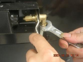
Step 2. remove the LP orifice and reattach the NG orifice
1. Turn back and keep the side burner base as figure
2. Use the wrench that attached in the hardware package, the small 6.1mm wrench hold to the
orifice and the bigger 18mm wrench used to hold the orifice connector, remove the LP
orifice
Step 3: replace the NG orifice and reassemble the side burner lid
1. Reset the NG orifice (1.7mm) use the same method as step 2
2. Reset the side burner base, the hinge rod and the side burner lid.
28Gas Conversion
Step 3: Replace Rear Burner Orifice
a. Remove rear baffle from bowl Assembly
b. Grasp brass elbow with vice grip
c. With 10 mm wrench remove LP orifices and replace with NG orifice(1.78mm)
d. Replace rear baffle
29Gas Conversion continued Step 4: Replace Searing Burner Orifice a. Remove the COTTER-PIN 2 screws on Searing burner and remove the burner b. Remove the 2 screws on the fire baffle in the front of Searing burner and remove the fire baffle panel. c. Remove the 1 screw on the Searing burner igniter. d. Locate LP-Orifice (inside front wall of firebox) & and use 7mm long socket to replace with NG-Orifice (2.1mm) e. Replace & Secure Burner. f. Replace all Burners, Flame-Tamers & Cooking-Grids. 30
Gas Conversion             continued

Step 4: Replace Oven Burner Orifice
a. Remove Back Access Panel from the rear panel (Fig 1)
b. Grasp brass elbow with vice grip or pliers (Fig 2)
c. With 10 mm wrench, remove LP orifice and replace with NG orifice(1.98mm) (Fig 3 & 4)
d. Insert orifices back and replace the access panel

              Fig 1                                                Fig 2

                  Fig 3                                             Fig 4

                                                                                          31
Gas Conversion Continued
Step 5: Remove Regulator
a. Use adjustable wrench to remove existing LP Gas regulator and Hose assembly.
b. If you are replacing an existing Natural Gas Grill, the supply hose that supplied
Natural Gas to the old Grill will work with your new Grill.
c. Replace the LP Gas regulator and hose assembly with a Natural Gas supply
hose and regulator (not supplied with the Grill). Follow installation instructions
as supplied by the manufacturer. The regulator might not be necessary. You
should contact the local Natural Gas company to determine if the gas pressure to
the property is Regulated (has a regulator in the system). If so then another
regulator is not necessary.
d. A new hose is not supplied with this Grill so as not to overcharge the consumer
for unnecessary parts.
Step 6: Check for Gas leak
Make sure you perform a leak test before operating the grill. Please refer to
Page 17 on the manual on how to test for gas leak.
Step 7: Adjustment of Control Valves for Main Burner, Side burner.
a Remove the black rubber ring on the control knob
b Remove all control-knobs with 5/32” Allen wrench (provided)
c. Adjust gas valve through access hole at knob-bezel by inserting a flat head
screw-driver. Turn the screw driver clockwise (to tighten) until it stops. (Not: it may
already be fully turned so it will not turn further). Then turn it counterclockwise (to
loosen) for one full revolution (360 deg, per revolution)
d. Adjust gas valves on the side burner.
e. Replace & secure knobs
32Care and Maintenance
MAIN GRILL BURNER CLEANING
STAINLESS STEEL
Ensure the gas supply is off and the knobs are
The grill is made from non-rusting and 430 in the “OFF” position. Make sure the grill is cool.
stainless steel. There are many different Clean the exterior of the burner with a wire
stainless steel cleaners available. Always brush. Clear stubborn scale with a metal
use the mildest cleaning procedure first, scraper. Clear any clogged ports with a
scrubbing in the direction of the grain. To straightened paper clip. Never use a wooden
touch up noticeable scratches in the toothpick as it may break off and clog the port.
stainless steel, sand very lightly with dry 100 Please note if insects or other obstructions are
grit emery paper in the direction of the grain. blocking the flow of gas through the burner, and
Specks of grease can gather on the if so you will need to call our customer service
surfaces of the stainless steel and bake on line 1-800-648-5864.
to the surface and give the appearance of
rust. For removal use an abrasive pad in GREASE TRAY CLEANING:
conjunction with a stainless steel cleaner. The grease tray should be emptied and wiped
GRILL RACK The easiest way to clean the down periodically and washing with a mild
detergent and warm water solution. A small
grill is immediately after cooking is
completed and after turning off the flame. amount of sand or cat litter may be placed in
Wear a barbeque mitt to protect your hand bottom of grease tray to absorb the grease.
from the heat and steam. Dip a brass bristle Check the grease tray frequently, don’t allow
barbeque brush in tap water and scrub the excess grease to accumulate and overflow out
hot grill. Dip the brush frequently in the bowl of the grease tray.
of water. Steam, created as water
BURNER CLEANING:
contacts the hot grill, assists the cleaning
process by softening any food particles. The 1. Turn off the gas supply, and make sure all
food particles will fall and burn. If the grill is the knobs are in the “OFF” position.
allowed to cool before cleaning, cleaning will 2. Wait for the grill to cool.
be more difficult.
3. Clean the exterior of the burner with a wire
ENSURE THAT THE GAS SUPPLY AND brush. Use a metal scrapper for stubborn
THE KNOBS ARE IN THE “OFF” POSITION. stains.
MAKE SURE THE TOP BURNERS ARE
4. Clear clogged port with a straightened
COOL REMOVAL. paper clip. Never use a wooden toothpick
Extreme care should be taken when replacing as it may break off and clog the port
a burner as it must be correctly centered on 5. If insects or other obstructions are blocking
the orifice before any attempt is made to the flow of gas through the burner, call
relight the grill. Frequency of cleaning will customer service at 1-800-648-5864
depend on how often you use the grill. Make sure to place the burner onto the orifice.
OVEN RACKS:
Clean stainless steel oven racks with solution of
detergent and hot water. To clean heavy soil, use
33 of
a scouring pad such as steel wool with plenty
water. 33Care and Maintenance Continued
HOW TO REPLACE MAIN BURNER STAINLESS STEEL :
Step 1. Insert the burner onto the orifice. There are many different stainless steel
cleaners available. Always use the mildest
cleaning procedure first, scrubbing in the
direction of the grain. Do not use steel wool
as it will scratch the surface. To touch up
noticeable scratches in the stainless steel,
sand very lightly with dry 100 grit emery
paper in the direction of the grain.
BURNER GRATE:
The top burner grate is porcelain coated
Step 2. Secure the main burner on the back cast iron. To avoid burns do not clean a hot
wall of fire box with 1 screw. grate. They may be wiped while in place
with hot, soapy water, rinsed and wiped dry.
Never immerse a hot grate in water.
CAUTION:
1. Keep outdoor cooking gas appliance
area clear and free from combustible
materials, gasoline and other flammable
vapors and liquids.
2. Do not obstruct the flow of combustible
and ventilation air.
3. Keep the ventilation openings of the
cylinder enclosure free and clear from
debris.
34Oven Maintenance and Cleaning
CLEANING INSIDE THE OVEN:
Bottom of the oven is partially covered by the Oven Bottom Cover and flame tamer.
This cover may be removed for cleaning by lifting it up and out of the oven.
The interior parts of the oven are porcelain coated. They are all easily cleaned.
Care should taken so as not to drip water into the small holes (ports) on the burner.
After cleaning, be sure to replace the flame tamer and the oven cover
35Remove the oven door
The oven door can be removed for cleaning. Please see the following illustrations.
Oven Door Disassembling as shown in the figure:
1,Open the oven door entirely, lock the iron piece to 2.Keeping the door at 30-45 degrees angle, lift
the hook of the door hinge. the door, pull it up & out of the frame
Oven Door Assembling as shown in the figure
Picture# 1
Picture# 2
36
Picture# 3Trouble Shooting
SPIDER AND INSECT WARNING!!! WHEN TO LOOK FOR SPIDERS
You should inspect the burners at least once
Checking and cleaning burner/ venturi tubes a year or immediately after any of the
for insects and insect nests. A clogged tube following conditions occur:
can lead to a fire beneath the grill. 1. The smell of gas in conjunction with the
burner flames appearing yellow.
Spiders and small insects occasionally spin 2. The grill does not reach temperature.
webs or make nests in the grill burner tubes
during transit and warehousing. These webs 3. The grill heats unevenly.
can lead to gas flow obstruction which could 4. The burners make popping noises.
result in a fire in and around burner tubes.
This type of fire is known as “FLASH-BACK”
and can cause serious damage to your grill
and create an unsafe operating condition for BEFORE CALLING FOR SERVICE
the user.
If the grill does not function properly, use the
Although an obstructed burner tube is not following check list before contacting your
the only cause of “FLASH-BACK”, it is the customer service. You may save the cost of a
most common cause. service call. “Please check page 52”
To reduce the chance of “FLASH-BACK”,
you must clean the burner tubes before
assembling your grill, and at least once a
month in late summer or early fall when
spiders are most active. Also perform this
burner tube cleaning procedure if your grill
has not been used for an extended period of
time.
37Trouble Shooting continued
PREHEATING: The grill lid should be in a closed position during the preheat time period. It is
necessary to preheat the grill for a short time before cooking certain foods, depending on the type of
food and the cooking temperature. Food that requires a high cooking temperature needs a pre-heat
period of five minutes; food that requires a lower cooking temperature needs only a period of two to
three minutes. There is no need to preheat for casseroles or other foods that require slow cooking.
COOKING TEMPERATURES
High setting-Use this setting for fast warm-up, for searing steaks and chops, and grilling.
Low setting-Use this setting for all roasting, baking, and when cooking very lean cuts such as fish.
These temperatures vary with the outside temperature and the amount of wind.
Cooking with in-direct Heat: You can cook poultry and large cuts of meat slowly to perfection on one side
of the grill by indirect heat from the burner on the other side. Heat from the lighted burner circulates gently
throughout the grill, cooking the meat or poultry without any direct flame touching it. This method greatly
reduces flare-ups when cooking extra fatty cuts, because there is no direct flame to light the fats and
juices that drip down during cooking. Place a drip pan slightly smaller than the cut of meat on the flame
tamer surface under the meat being cooked. This will allow you to catch meat juices for making gravy.
Flare-Ups: The fats and juices that drip from the meat cause flare-ups. Since flare-ups impart the
distinctive taste and color for food cooked over an open flame, they should be expected and encouraged
within reason.
Nevertheless, uncontrolled flaring can result in a ruined meal.
CAUTION: If burners go out during operation, close gas supply at source, and turn all gas valves off.
Open lid and wait five minutes before attempting to re-light (this allows accumulated gas fumes to clear).
CAUTION: Should a grease fire occur, close gas supply at source, turn off all burners and leave lid closed
until fire is out.
CAUTION: DO not attempt to disconnect any gas fitting while your barbecue is in operation. As with all
appliances, proper care and maintenance will keep them in top operation condition and prolong their life.
Your gas gill is no exception.
38Trouble Shooting continued
PROBLEM SOLUTION
When attempting to light my grill, it will not • Make sure you have a spark while you are trying to light
light immediately. the burner (if no spark)
• Ensure that the wire is connected to the electrode
assembly.
• Clean wire (s) and / or electrode with rubbing alcohol
and a clean swab. Wipe with a clean cloth.
• Check to see if the other burners operate. If so. Check the
gas orifice on the malfunctioning burner for an obstruction.
Rotisseries burner will not light when the • Check to see if debris is blocking the electrode.
igniter button is pushed. • Check to see if there is a spark that jumps to the burner
from the electrode. If no spark is seen, check the battery
located inside the igniter button. To open turn counter
clockwise.
Remove. It was combined with #2
Is OK.
• Gently bend the electrode closer to the burner until a spark
is seen to jump from the electrode to the burner when you
push the igniter button.
• Does the infrared back burner light when attempting to
light with a match ? If not, check to ensure the gas is on.
Regulator makes noise. • Vent hose on the regulator may be plugged or regulator
may be faulty.
• Ensure the vent hole on the regulator is not obstructed.
Clear the hole, close the gas control valves. Wait ten
minutes and re-start.
• Check your flames for proper performance if the flames
are not correct replace regulator.
Full size cover does not fit the grill. • Cover may be incorrect for your grill. It may be a tight fit.
Ensure the cover is the correct length for your grill.
Measure it left to right. Compare to the grill’s
measurement.
• Compare the location and size of the hood portion of the
cover to your grill.
• Spread the cover and allow it to relax, preferably in warm
sunlight or in a warm room.
• For grill with a side shelf bunch the cover like a sock, put
on left to right.
39Trouble Shooting continued
Rotisserie motor will not turn • Ensure the motor is connected to a properly grounded
power supply.
• Ensure the on / off switch is in the on position.
• Ensure that the spit is fully inserted into the rotisserie
motor
• Ensure that the load does not exceed the 40 pound
operational capacity.
• Ensure that there is no encumbrance or drag.
Grill only heats to 200-300 degrees. • Check to see if the fuel hose is bent or kinked.
• Make sure the grill area is clear of dust.
• Make sure the burner and orifices are clean.
• Check for spiders and insects.
• The regulator has a safety device that restricts the flow of
gas in the event of a leak. This safety device can be
triggered with out a gas leak. To reset the safety device,
turn off all burners and close the LP tank valve. Disconnect
the regulator from the LP tank and wait one minute.
Reconnect the regulator to the LP tank and slowly open the
LP tank valve until the valve is fully open. Light all burners
and observe the temperature.
Grill takes a long time to preheat. • Normal preheat 500-600degrees, takes about 10-15 min.
Cold weather and wind may effect your preheat time.
• If you are using volcanic rock or briquettes they can
increase the preheat time and maximum temperature.
Burner flames are not light blue. --Too much or not mixture air mixture for the flame.
--Elevation is the principal cause, however cold weather
can affect the mixture. Burner adjustment may be
required. --Grill is in a windy location.
40
39LP Explode View
01
02
03
04
11
05 111
06
12 07
13 03
02
23 08
14
16 10
15 9 106
22
17
28 105 117
18 21
29
23 104
24 103 116
25 115
26 102
27
98
30 97
100
31 99 96
101 87 95
32
35 88
33 34
38 86
85 94
83
93
36 37 39 84
82 92
40
81
41
71 80
90
42 89
70 68 79
67 78
43 69
66
20
19 77
114 44 73 91
45
72
46 76
47 65
64 75
48 62
74
59 61 60
50
51 63
52
53
54
59
55 58
56 57
41Part List
NO PART (DESCRIPTION) QTY NO PART (DESCRIPTION) QTY
1 Main Lid 1 33 Control knob 7
2 Main lid screw cover 2 34 Main manifold 1
3 Main lid screw 2 35 Main Gas Valve 4
4 Temperature gauge housing 1 36 Grease Tray handle 1
5 Heat indicator 1 37 Grease Tray 1
6 Logo 1 38 side panel, left 1
Main Lid Handle Heat Insulating
7 Spacer 2 39 Cart Frame, Front 1
8 Main Lid Handle seat, left 1 40 lighting Rod 1
9 Main Lid Handle seat, right 1 41 Door hinge 1
10 Main Lid Handle Tube 1 42 Door handle 1
11 Side Burner Lid Hinge screw 2 43 smoke canister outer cover upper plate 1
12 Side burner lid 1 44 smoke canister outer cover left plate 1
13 Side burner cooking grid 1 45 Oven base support 2
14 Side burner head 1 46 Oven Bottom cover 1
15 Side burner pipe 1 47 Igniter hot surface 1
16 Side burner pipe bracket 1 48 Door Frame, Inner 1
17 Side Burner Flex Gas Line 1 49 Door Gasket 1
18 Side Burner bowl assembly 1 50 Rear plate for oven door 1
19 Swivel caster without brake 1 51 Oven back panel inside liner 1
20 Oven lamp cover 1 52 Door hinge, left 1
21 sear burner 1 53 Oven Window 1
22 Sear burner Igniter Wire 1 54 Oven Window Glass 1
23 Regulator, LP 1 55 Oven Door handle 1
24 Thermocouple gas valve 1 56 Oven Door 1
25 Side burner gas valve 1 57 Door hinge, right 1
26 Thermostat Valve 1 58 Hinge Receptacle 2
27 Pulse Igniter Module 1 59 Oven Rack 2
28 Side Shelf, left 1 60 Oven Burner-U Shape 1
29 Side shelf control panel , left 1 61 Ignitor Hot Surface Bracket 1
30 Main Control Panel 1 62 Flame Tamer, oven 1
31 indicating light 1 63 smoke canister outer cover right plate 1
42
32 Control knob (thermocouple) 1 64 Oven 1
42Part List Continued
Q' Q'T
PART (DESCRIPTION)
NO TY NO PART (DESCRIPTION) Y
65 Oven Plate, Rear 1 93 back access panel 1
66 Oven Lamp 1 94 Rubber Grommet 2
67 Oven Flue 1 95 back panel 1
68 Oven Grill Inside Liner 1 96 Rotisserie motor bracket 1
69 Front Door, left 1 97 Rotisserie motor 1
70 Door magnet 1 98 Spit Fork 2
71 Lighting Rod Cover 1 99 Spit Rod 1
72 U-shape Burner Orifice 1 100 Shaft Collar 1
Ceramic Hot Surface Igniter Conduit
1 1
73 Clip 101 front baffle
74 Oven Bottom Panel, LP 1 102 Main burner bowl assembly 1
75 Ceramic Hot Surface Igniter Conduit 1 103 main burner 4
76 U Shape Burner Side Plate 2 104 flame tamer 4
77 Swivel caster with brake 1 105 cooking grid with hole 3
78 Center panel 1 106 warming rack 1
79 door magnet bracket 1 107 Rotisserie Burner Igniter Wire 1
80 Caster 2 108 Rotisserie burner 1
81 Bottom Panel,LP 1 109 rotisserie burner flex gas line 1
82 Power box 1 110 rotisserie burner w/brass elbow 1
83 cable strainer 1 111 Rotisserie burner wind shield 1
84 cable strainer securing plate 1 112 Rotisserie burner Ignition bracket 1
85 Stainless Tube, Safety Valve to Gas B 1 113 Rear Baffle 1
86 safety valve, bake 1 114 oven upper panel insulation plate 1
87 Stainless Tube, Safety Valve to Gas A 1 115 rotisserie gas valve 1
88 strainer tube securing plate 1 116 Regulator fasten piece, NG 1
Regulator Assembly, NG ( not
side shelf push bar, right 1 1
89 117 included)
90 side shelf, right 1 118 manual 1
91 Side shelf control panel , right 1 119 Hardware package 1
1
92 side panel, right
43You can also read