2 Speed axial piston motor - X70 Plugin motor catalog - ATP Hydraulik

Page created by Lawrence Zimmerman
 
CONTINUE READING
2 Speed axial piston motor - X70 Plugin motor catalog - ATP Hydraulik
40.6 to 49.2 cc [2.48 to 3.00 in3/r]
X70 Plugin motor catalog   280 to 350 bar [4060 to 5076 psi]

2 Speed axial piston motor
Table of contents
Features.......................................................................................................................03
                                                                                                                                    1
Hydraulic schematic...................................................................................................03
                                                                                                                                    1
Technical specifications.............................................................................................04
                                                                                                                                    1
Model code structure.................................................................................................05
                                                                                                                                    1
Loop flushing valve.....................................................................................................06
                                                                                                                                    1
Anti-cavitation valve..................................................................................................07
                                                                                                                                    1
Brake release port.......................................................................................................08
                                                                                                                                    1
Motor installation drawings......................................................................................09
                                                                                                                                    1
Shaft installation drawing.........................................................................................10
                                                                                                                                    1
Component selection guide......................................................................................10
                                                                                                                                    1
Hydraulic fluid recommendations............................................................................12
                                                                                                                                    1
                                                                                                                                    1
                                                                                                                                    1
                                                                                                                                    1
                                                                                                                                    1
                                                                                                                                    1
                                                                                                                                    1
                                                                                                                                    1
                                                                                                                                    1
                                                                                                                                    1
                                                                                                                                    1
                                                                                                                                    1
                                                                                                                                    1
                                                                                                                                    1
                                                                                                                                    1
                                                                                                                                    1
                                                                                                                                    1
                                                                                                                                    1
                                                                                                                                    1
                                                                                                                                    1

2                       X70 PLUGIN MOTOR CATALOG             E-MOPI-CC004-E—April 2019      www.eaton.com
2 Speed axial piston motor

Features                                                                                                                                   1
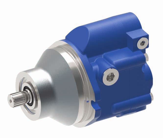
Eaton Medium Duty Piston Motors convert hydraulic                     Field proven rotating group design
                                                                                                                                           1
                                                                  •
energy supplied by the pump to mechanical energy.                 •   2 speed option
These motors are uniquely suited to fit any application
that requires continuous rotary motion at a remote location
                                                                  •   Direct hydraulic operated control                                    1
from the power source. Axial piston motors share the design
                                                                  •   Compact design
advantages of piston pumps to provide long-lasting power          •   Brake release port to use with gear box                              1
in a lightweight, easily serviceable package. The table below     •   Planetary gear box option
provides an overview of features. For a complete list             •   Hot oil shuttle & anti-cavitation check valve                        1
of options, refer to the Model Code section of a given
motor displacement.                                                                                                                        1
                                                                                                                                           1
Hydraulic schematic
                                                                                                                                           1
                                                                      P                                                R                   1
                                                                                                                                           1
           A
                                                                                                                                           1
                                                     Optional

                                                                                                            Optional                       1
                                                                                                                                           1
                                                                                                                                           1
                                                                                                                                           1
                                                  MIN           MAX                                                                        1
                                                                                                                                           1
                                                                                                                                           1

           B
                                                                                                                                           1
                                                                                                                                           1
                                                                                                                                           1
                                                                                                                       Gearbox brake
                                                                                                                       release port        1
                                                                                                                                           1
                                                                                                                                           1
                                                                                                                                           1
                                                                                                                                           1
                                                                                                                                           1
                                                                                                                                           1
                                                                                                                                           1
                                                                                                                                           1

                                           X70 PLUGIN MOTOR CATALOG        E-MOPI-CC004-E—April 2019   www.eaton.com                   3
2 Speed axial piston motor

1   Technical specifications
1
    Parameter                           Unit                     Model 374AKXXXXXA (41 cc)                  Model 374AKXXXXXA (49 cc)

1   Displacement                        cm 3 /r [in 3 /r]        40.6 [2.48]                                49.2 [3.00]
    Maximum displacement                cm 3 /r [in 3 /r]        32.0 to 40.6 [1.95 to 2.48]                43.3 to 49.2 [2.64 to 3.00]
1   Minimum displacement                    3       3
                                        cm /r [in /r]            7.4 [0.45], 10 [0.61], 13 [ 0.79],         16.30 [0.99], 20 [1.22], 22 [1.36], 26 [1.58],
                                                                 17 [1.037], 20.5 [1.25]                    29 [1.77], 32 [1.95]
1   Maximum rated speed at              rpm                      3500                                       3500
    maximum displacement
1   Maximum rated speed at
    minimum displacement
                                        rpm                      4500                                       4500

1   Nominal pressure rating *           bar [psi]                350 [5076]                                 310 [4500]
    Peak pressure rating **             bar [psi]                380 [5500]                                 345 [5000]
1   Output torque (theoretical)         N-m / bar
                                        [lbf-in/1000 psi]
                                                                 0.65 [394]                                 0.79 [480]

1   Shift pressure range                bar [psi]                15 - 69 [220 to 1000]                      15 - 69 [220 to 1000]
    Maximum allowable case pressure     bar [psi]                3.45 [50]                                  3.45 [50]
1   Viscosity - Minimum                 cSt                      6 cSt                                      6 cSt
    Viscosity - Optimum working range   cSt                      10-39 cSt                                  10-39 cSt
1   Viscosity - Maximum                 cSt                      2158 cSt                                   2158 cSt
    Maximum Fluid Temp-Inlet            °C                       105 degree celcius                         105 degree celcius
1   Minimum Fluid Operating Temp        °C                       -30 degree celcius                         -30 degree celcius
    Ambient Temperature                 °C                       -30 to 80 degree celcius                   -30 to 80 degree celcius
1   Weight                              lbs [kg]                 36 lbs [16.36 kgs]                         36 lbs [16.36 kgs]
    Cleanliness                                                  21/18/13 ISO/DIS 4406 (Class 9)            21/18/13 ISO/DIS 4406 (Class 9)
1   NNotes:
    * Nominal pressure : Max. delta system pressure at which component fatigue does not occur. (Motor life estimated by bearing life
1   ** Peak pressure : Max. operating pressure which is permissible for a short duration of time [t
2 Speed axial piston motor

Model code structure                                                                                                                               1
                                                                                                                                                   1
    X7M       49     A        01       A     1      A    0    0      1   1       32       00       0     1     0      00      2     00         A
                                                                                                                                                   1
1 2 3         4 5     6      7 8       9     0      1    2    3      4   5       6 7     8 9       0     1     2      3 4     5    6 7         8
                                                                                                                                                   1
1    2    3                                                                               07       7.37 cm3/r [0.45 in3/r]
                Code title
                                                                                          10       10.65 cm3/r [0.65 in3/r]                        1
                X7M       X70 variable displacement piston motor
                                                                                          11       11.47 cm3/r [0.70 in3/r]
4    5          Displacement                                                              13       13.44 cm3/r [0.82 in3/r]
                                                                                                                                                   1
                41        40.6 cm3/r [2.48 in3/r]                                         16       16.30 cm3/r [1.00 in3/r]
                                                                                                                                                   1
                49        49.2 cm3/r [3.00 in3/r]                                         17       17.53 cm3/r [1.07 in3/r]

6               Mounting flange
                                                                                          20       20.48 cm3/r [1.25 in3/r]                        1
                                                                                          22       22.45 cm3/r [1.37 in3/r]
                A         Plug-in mount
                                                                                          26       26.85 cm3/r [1.64 in3/r]                        1
7    8          Output shaft                                                              32       32.00 cm3/r [1.95 in3/r]
                01        15 Tooth 16/32 Spline                          18 19
                                                                                                                                                   1
                                                                                          Maximum displacements
                02        13 Tooth 16/32 Spline
                                                                                          00       Catalogue motor displacement                    1
                03        Taper 1:8 Per SAE J501
                                                                                          33       33.1 cm3/r [2.02 in3/r]
9               Main ports sizing                                                         35       35.6 cm3/r [2.17 in3/r]                         1
                                                                                          38       38.0 cm3/r [2.32 in3/r]
                A         M27 X 2 Metric O-Ring port (A & B)
                                                                                          43       43.3 cm3/r [2.64 in3/r]
                                                                                                                                                   1
                B         1.0625-12 UN-2B SAE o-ring port (A & B)
10              Port orientation
                                                                                          45       45 cm3/r [2.75 in3/r]
                                                                                                                                                   1
                                                                                          47       47 cm3/r [2.87 in3/r]
                1      Radial ports
                2      Axial ports                                       20               Auxiliary mounting (rear)                                1
11              Motor control options
                                                                                          0        No auxiliary mounting
                                                                                                                                                   1
                                                                         21               Speed sensor option
                A         Single input directly operated, external
                          control supply, without pilot valve                             0        No speed sensor
                                                                                                                                                   1
12              Control solenoids                                                         1        Speed sensor ready (plugged port)
                                                                                                                                                   1
                                                                                          2        With speed sensor
                0         None
                                                                         22               Shaft seal option                                        1
13              Supply orifice
                                                                                          0        Standard nitrile
                0      No orifice                                                                                                                  1
                1      0.53 [0.021] orifice                              23 24            Special features
14              Valving                                                                   00       No special features                             1
                0      No valves                                         25               Paint                                                    1
                1      Shuttle valve with loop flushing
                                                                                          0        Do not paint (Anti rust conservation oil)
                2      Blocked shuttle valves
                                                                                          1        Painted primer blue (Per spec 209-13CD)         1
                3      Anti cavitation valve, unidirectional LH
                                                                                          2        Painted primer black (Per spec 209-13B)
                          (CCW) Rotation
                                                                                          3        Green per spec 209-13K
                                                                                                                                                   1
                4         Anti cavitation valve, unidirectional RH
                          (CW) Rotation                                                   4        Grey per spec 209-13P
                                                                                                                                                   1
                                                                                          5        Red per spec 209-13V
15              Flushing valve pressure setting
                0         None
                                                                                          6        Yellow per spec 209-13BF                        1
                                                                                          7        Bright yellow per spec 209-13CF
                1         10.3-12.1 bar [150-175 PSI]
                                                                         26 27            Identification
                                                                                                                                                   1
                2         11.4-13.1 bar [165-190 PSI]
                3         13.8-15.9 bar [200-230 PSI]                                     00    Standard                                           1
                4         15.2-17.2 bar [220-250 PSI]                                     Design code
                                                                         28
                5         20.0-21.4 bar [290-310 PSI]                                                                                              1
                                                                                          A        A

16 17           Minimum displacements
                                                                                                                                                   1

                                                    X70 PLUGIN MOTOR CATALOG     E-MOPI-CC004-E—April 2019   www.eaton.com                     5
2 Speed axial piston motor

1   Loop flushing valve
    The spring centered shuttle valve, located in the motor’s
1   end cover, moves to connect the low pressure side of the
    loop to the low pressure relief valve. When back pressure
1   gets high enough the low pressure relief valve, in the end
    cover, opens and charge pump flow enters the motor case.
1   Case flow flushes the pump and motor cases and helps
    keep the transmission cool. The low pressure relief valve in
1   the motor’s end cover typically has a lower setting than the
    charge pressure relief valve in the charge pump. This is so
1   case flow will begin at the motor, go to the pump, and return
    to the reservoir.
1
1
1
1
1
1
1
1
1
1
1
1
1
1
1
1
1
1
1
1
1
1
1
1

    6                 X70 PLUGIN MOTOR CATALOG   E-MOPI-CC004-E—April 2019   www.eaton.com
2 Speed axial piston motor

Anti cavitation valve                                                                                                                  1
Anti-cavitation valve is to prevent the cavitation of the motor    allow flow from delivery side back to suction side of motor.
during deceleration and spin down. These are the conditions        So, ultimately motor suction will get the required flow to run      1
in which pump does not generate sufficient flow to fulfill         motor at desired speed.
motor requirements. Reduced flow creates vacuum at the             •   For this option the high pressure port needs to be defined
                                                                                                                                       1
motor suction which intern reduces pressure below partial              upfront to get the correct motor rotation. Reversing the
pressure and arises cavitation. By introduction of the check           motor is not possible with this option.                         1
valve in the circuit this condition will get eliminated as it
                                                                                                                                       1
                                                                        P                                   R
                                                                                                                                       1
              A                                                                                                                        1
                                                        Optional                                                                       1
                                                                                                                                       1
                                                                                              Optional                                 1
                                                                                                                                       1
                                                                                                                                       1
                                                     MIN          MAX
                                                                                                                                       1
                                                                                                                                       1
                                                                                                                                       1
              B                                                                                                                        1
                                                                                                                                       1
                                                                                                                   Gearbox brake       1
                                                                                                                   release port
                                                                                                                                       1
                                                                                                                                       1
                                                                                                                                       1
                                                                                                                                       1
                                                                                                                                       1
                                                                                                                                       1
                                                                                                                                       1
                                                                                                                                       1
                                                                                                                                       1
                                                                                                                                       1
                                                                                                                                       1
                                                                                                                                       1

                                             X70 PLUGIN MOTOR CATALOG       E-MOPI-CC004-E—April 2019   www.eaton.com              7
2 Speed axial piston motor

1                                                                             P                              R

1
                 A
1                                                           Optional
1
1                                                                                                 Optional

1
1
1                                                       MIN          MAX

1
1
1                B
1
1
                                                                                                                 Gearbox brake
1                                                                                                                release port

1
1
1   Brake release port
    X70 series plugin motors are provided with a brake                 While all motors will have the brake release port, not all
1   release port to allow the user to make an access to the            gearboxes are compatible with this motor feature. Get in
    brake-release feature of the machine gear box from the             touch with your EATON representative in case of queries.
1   rear side of the motor.                                            The rated pressure for the brake release port on the motor
    A brake release port is a simple passage provided on the           housing is 250 bar (this does take into account the O-ring
1   motor to pass the fluid. For this, housing is provided with        interface between the motor and gearbox). Check your
    a rear-facing 7/16 in. SAE O-ring boss port. Refer the             gearbox for compatibility of this feature. If found as not
1   installation drawings for the specific positioning of the          compatible, do not connect this port to any fluid lines.
                                                                       Leave it plugged as shown in installation drawings.
    release port. Applications using this brake release port
1   require an O-ring to seal the passage against the gear box.

1
1
1
1
1
1
1
1

    8                 X70 PLUGIN MOTOR CATALOG    E-MOPI-CC004-E—April 2019       www.eaton.com
2 Speed axial piston motor

Motor installation drawings                                                                                                                                     1
  Requires an o-ring: Viton 75 Durometer
  cross section -2.6 ± 0.07[0.103 ± 0.003]
                                                                                                                                                                1
  I.D. -126.6 ± 0.8[4.987 ± 0.035]
                                                                                                                                                                1
                                                                                                                                                                1
                                                                                                                                                                1
                                                                                                                                                                1
                                                                                                                         155.4

25.4                                                                                                   71.1 [2.80]
                                                                                                                         [6.12]
                                                                                                                                                                1
[1.00]                                                                                                (case drain)
                                                                                                                                                                1
                                  Case drain side

                 36.6
                                  .750 - 16 UNF -2B
                                  SAE o-ring port                              81.3       126.9                                                                 1
                 [1.44]           (shown plugged)                             [3.20]      [5.00]
                                                                                                                                                                1
   Mating o-ring min
   installed inside Ø4.8 [0.19]
                                                                                        112.7
                                                                                        [4.44]                                                                  1
                                                                                                       Control port
                                                                                                       .5625 - 18 UNF - 2B
                  71.9
                 [2.83]                                                         36.6
                                                                               [1.44]
                                                                                                       SAE o-ring port                Brake release port
                                                                                                                                      .4375 - 20 UNF - 2B
                                                                                                                                                                1
                                                          Case drain side
                                                                                                                                      SAE o-ring port
                                                          .750 -16 UNF - 2B
                                                          SAE o-ring port                                                             (shown plugged)           1
                                                          (shown plugged)

22.1
                                             102.4
                                                                                                            72.9
                                                                                                                                                  22.1          1
                                             [4.03]         135                                                                                   [.87]
[.87]                                                                                                      [2.87]
                                                           [5.31]
                                                                                                                                                                1
                                                                86.4
          6.1
         [.24]
                                     2X 13.7
                                        [.54]
                                                               [3.40]                                  40.6
                                                                                                      [1.60]                                                    1
    2X R6.4
       [.25]      0.3
                                                  76.2
                                                                                                                                                                1
                 [.01]
                                                 [3.00]
    2X 77.5
      [3.05]                         2X 86.1
                                                                                           37.6
                                                                                          [1.48]
                                                                                                                                   71.9
                                                                                                                                  [2.83]
                                                                                                                                                                1
                                       [3.39]
                                                                                                                                                                1
                                                                                                               Main ports
                                                                                                               1.0625 - 12 UN - 2B                              1
                                                                                                               SAE o-ring port

                                                                                                                         29.2                                   1
                                                                                                                        [1.15]
                                                                                                                                                                1
                                                      70.1[2.76]
                                                      (case drain)
                                                                                                                     29.2                                       1
                                                                                                                    [1.15]
                                                                                                                                                                1
                                                                               13.5
                                                                               [.53]
                                                                                        102.5
                                                                                                                                                                1
                                                                                        [4.04]
                                                                                                                                                                1
                                                                                                                                                                1
                                                                                                                                                                1
                                                                                                                                                                1
                                                                                                                                                                1

                                                        X70 PLUGIN MOTOR CATALOG        E-MOPI-CC004-E—April 2019     www.eaton.com                         9
2 Speed axial piston motor

1   Shaft installation drawings
1                               115.8
                                [4.56]

1                                                         15 Tooth
                                                          30º flat root
                                                          side fit 16/32
1                                                         class 5 spline
                                                          per ANSI B92.1

1                                                                Ø 24.9
                                                                  [.98]
1
1
                                                                           Hydraulic System
1                                                        20.3              Design Calculations
                                                         [.80]
1
1
1
1                                                                          Basic Formulas                                          Efficiencies
                                                                                                                                   Volumetric Nv =
1   Component selection                                                    Output Flow (Q)
    The long service life of Eaton hydrostatic transmissions is                                                                    Mechanical Nm =
1   largely dependent on the proper selection and installation of          lpm =
                                                                                      cm33/r x rpm
                                                                                                     gpm =
                                                                                                                in33/r x rpm
    the components necessary for transmission operation.                                 1000                          231
                                                                                                                                   Total Nt = Nv x N
1   The following components are necessary for                             Input Power (P)
    transmission operation:
1   •    Variable displacement pump                                        kW =
                                                                                      l/min x bar
                                                                                                     hp =
                                                                                                                gpm x psi
                                                                                         600                       1714
1   •    Fixed or variable displacement motor
    •    Reservoir                                                         Shaft Torque (M)
1   •    Filter
    •    Charge pump inlet line                                                  bar x cm33/r                       psi x in33/r
                                                                           N-m =                     lb-in =
1   •    Pump and motor case drain lines                                            62.8                                6.28
    •    High pressure lines                                               Shaft Speed (n)
1   •    Heat exchanger
         Heat exchanger bypass valve                                                  1000 x l/min              231 x gpm
1
    •
                                                                           rpm =                     RPM =
    •    Reservoir return line                                                           cm33/r                      in33/r
                                                                                                                                   Commonly U
1                                                                          Output Power (P)

    VariableHydraulic        System                                                                                                To Convert

1            displacement pump                                                        N-m x RPM                 lb-in x rpm        bar
           Design
    Eaton hydrostatic      Calculations
                      variable displacement pumps are an
                                                                           kW =
                                                                                         9549
                                                                                                     hp =
                                                                                                                    63,025         cm33
1   axial piston design. They are equipped with standard SAE
                                                                           Volumetric Displacement
                                                                                                                                   ˚C
    mounts, shafts and port connections.                                                                                           gallons (US)
1                                                                                       lpm x 1000                  gpm x 231      kg
                                                                           cm33/r =                  in33/r =
                                                                                           rpm                          rpm        kgf/cm22
1   Fixed or variable displacement motor                                                                                           kW
                                                                                                                                   liters
1   Eaton hydrostatic motors are an axial piston design.
           Basic Formulas
    They are equipped with standard SAE mounts, shafts and
                                                                           Efficiencies
                                                                           Basic   Formulas   gpm actual                           mm
                                                                           Volumetric  Nv =
    port connections.
1             Output Flow (Q)
                                                                                            gpm
                                                                           bar = 10 Newtons/cm 2 theorectical
                                                                                               2                                   N-m
                                                                           gpm   = gallons      lb-in actual                       N-m
    Sizing equations                                                       Mechanical   Nmper
                                                                                            = minute
1                 cm3/r x rpm
              lpm =                      gpm =
                                                 in3/r x rpm               hp = horsepower lb-in theorectical                      ˚F
    For sizing/selecting the right pump for your application
                       1000                      231                       lb-in                                                   hp
                                                                           Total=Ntpound
                                                                                    = Nv inch
                                                                                          x Nm
1   please carryout following basic calculations.
              Input Power (P)                                              lb-ft = pound feet                                      inch
                                                                           kW = kilowatt                        Q                  in33
                      l/min x bar                gpm x psi               kgf = kilograms force                                     lb-in
              kW =                    hp =                                                                                    p
    10                   X70
                         600 PLUGIN MOTOR CATALOG
                                                1714
                                                   E-MOPI-CC004-E—April 2019 www.eaton.com
                                                                         l/min = liters per minute                                 lb-ft
                                                                                                     n
                                                                           N-m = Newton meters P                                   lbs
2 Speed axial piston motor

Reservoir                                                        Filter
                                                                                                                                   1
The reservoir is an important part of the hydrostatic            A filter must be used to keep the hydraulic fluid clean. Either
transmission system. It should provide adequate oil storage      a suction filter or a pressure side filter may be used. The       1
and allow easy oil maintenance.                                  filter must be a no-bypass type. System oil particle levels
The reservoir must hold enough oil to provide a continuous       should not exceed ISO 18/15 per ISO 4406. Refer to Eaton
                                                                 Hydraulic Fluid Recommendations.
                                                                                                                                   1
oil supply to the charge pump inlet. It must also have
enough room for the hydraulic oil to expand as the system        Recommended filters                                               1
warms up. Consider charge pump flow when sizing the              Pressure line – 5 micrometer
reservoir: One half (.5) minute times (X) the maximum
charge pump flow should be the minimum oil volume in             Suction line = 3 OR 5 micrometer                                  1
the reservoir. Maintaining this oil volume will give the oil a
minimum of thirty (30) seconds in the reservoir. This will
                                                                 When a suction filter is used, its flow capacity must be large
                                                                 enough to prevent an excessive pressure drop between the
                                                                                                                                   1
allow any entrained air to escape and contamination to settle    reservoir and charge pump inlet. The pressure at the charge
out of the oil.                                                  pump inlet port must not be less than 0,80 bar absolute [6
                                                                                                                                   1
To allow for oil expansion, the reservoir’s total volume         in. Hg.] at normal continuous operating temperatures.
should be at least six tenths (.6) minute times (X) the
                                                                                                                                   1
maximum charge pump flow.                                        Charge pump inlet line
                                                                                                                                   1
The reservoir’s internal structure should cut down               The inlet line to the charge pump should be large enough
turbulence and prevent oil aeration.                             to keep the pressure drop between the reservoir and
                                                                 charge pump inlet within the limits described in the filter
                                                                                                                                   1
The line returning flow to the reservoir should be fitted with
                                                                 section. Fittings will increase the pressure drop, so their
a diffuser to slow the incoming oil to 1 to 1.2 meters [3-4
                                                                 number should be kept to a minimum. It is best to keep fluid
                                                                                                                                   1
feet] per second to help reduce turbulence. The return flow
                                                                 velocities below 1,25 meters [4 feet] per second.
line should also be positioned so that returning oil enters
the reservoir below the liquid surface. This will help reduce
                                                                                                                                   1
                                                                 Fluid and temperature compatibility must be considered
aeration and foaming of the oil.                                 when selecting the inlet line.
                                                                                                                                   1
The reservoir should have baffles between the return
                                                                 Pump and motor case drain
line and suction line. Baffles prevent return flow from                                                                            1
immediately reenter- ing the pump.                               The case drain lines should be large enough to limit the
A sixty mesh screen placed across the suction chamber            pump and motor case pressures (Medium Duty to 2 bar               1
of the reservoir will act as a bubble separator. The screen      [25 PSI]) at normal operating temperatures. Fluid and
should be placed at a 30° angle to the horizon.                  temperature compatibility must also be considered when
                                                                 selecting the case drain lines.
                                                                                                                                   1
The entrance to the suction line should be located
well below the fluid surface so there is no chance of air
                                                                 High pressure lines
                                                                                                                                   1
being drawn into the charge pump inlet. However, the
suction line entrance should not be located on the bottom        The high pressure lines that connect the pump and motor           1
of the reservoir where there may be a buildup of sediment.       must be able to withstand the pressures generated in the
The suction line entrance should be flared and covered           high pressure loop.                                               1
with a screen.
The reservoir should be easily accessible. The fill port         Heat exchanger                                                    1
should be designed to minimize the possibility of                Use of a heat exchanger is dependent on the transmission’s
contamination during filling and to help prevent over filling.   duty cycle and on machine layout. The normal continuous           1
There should be a drain plug at the lowest point of the          operating fluid temperature measured in the pump and
reservoir and it should also have a clean-out and inspection
cover so the reservoir can be thoroughly cleaned after
                                                                 motor cases should not exceed 80°C [180°F] for most               1
                                                                 hydraulic fluids.The maximum fluid temperature should not
prolonged use. A vented reservoir should have a breather
cap with a micronic filter.
                                                                 exceed 107°C [225°F].                                             1
                                                                 The heat exchanger should be sized to dissipate 25%
Sealed reservoirs must be used at altitudes above                of the maximum input power available to the transmission.         1
2500 feet.                                                       It must also be sized to prevent the case pressures in
These reservoirs should be fitted with a two- way                the pump and motor from getting too high. Medium duty             1
micronic filter pressure cap to allow for fluid expansion        case pressure up to 2 bar [25 psi], at normal operating
and contraction.                                                 temperatures, are acceptable.                                     1
In both cases the caps must be designed to prevent
water from entering the reservoir during bad weather or                                                                            1
machine washing.
A hydrostatic transmission with a well designed reservoir                                                                          1
will run quieter, stay cleaner and last longer.
                                                                                                                                   1
                                                                                                                                   1

                                             X70 PLUGIN MOTOR CATALOG     E-MOPI-CC004-E—April 2019   www.eaton.com           11
2 Speed axial piston motor

1   Heat exchanger bypass valve                                           Hydraulic fluid recommendations
    The heat exchanger bypass valve is a pressure and/or
1   temperature valve in parallel with the heat exchanger. Its            Introduction
    purpose is to prevent case pressures from getting too high.           Hydraulic fluids are one of the vital components of hydraulic
1   The heat exchanger bypass valve opens when the oil is
    thick, especially during cold starts.
                                                                          system. Proper selection of oil assures satisfactory life
                                                                          and operation of system components. The purpose of this
1   Reservoir return line
                                                                          section is to provide readers with the knowledge required to
                                                                          select the appropriate fluids for use in systems that employ
1   The same general requirements that apply to case drain                Eaton hydraulic components
    lines apply to the reservoir return line.
                                                                          Viscosity and temperature
1
    Bearing life estimation                                               Viscosity is the measure of a fluid’s resistance to flow. The
1   Bearing life is defined as the length of time in terms of             most important characteristics to consider when choosing
    revolutions or time until a fatigue failure. Bearing load is          a fluid to be used in a hydraulic system is viscosity. The
1   calculated as a reaction which is derived from the moment             fluid must be thin enough to flow easily but thick enough to
    created by the piston side load. Magnitude of the side load           maintain adequate lubricating film between components and
1   directly related to the speed and pressure at which a unit            to maintain proper sealing at the operating temperatures of
                                                                          the hydraulic system.
    can be operated.
1   Bearing life is a function of the side loads coming on the            For viscosity requirements, see table
    bearings. Other factors such as fluid type, viscosity of fluid        Viscosity of any fluid is relative to temperature, as the
1   and cleanliness also affects the life of bearing.                     fluid warms the viscosity decreases and vice versa. When
    If detail bearing life analysis is required, you can contact          choosing a fluid, it is important to consider the start-up and
1   Eaton representative.                                                 operating temperatures of the hydraulic system. A high
                                                                          VI fluid shows relatively small change of viscosity with
1   Installation requirements                                             temperature.
                                                                          Lubricants used for hydraulic applications may contain
    The mounting orientation of pumps and motors is
1   unrestricted provided the case drain of the pump and motor
                                                                          viscosity index improvers (VII). They refer to these fluids
                                                                          as viscosity index improved or multi-viscosity fluids. The
    remain full.Position the case drain such that it assures an oil
1   level at or above unit center line at start-up. The case drain
                                                                          viscosity of these fluids may drop down in use due to
                                                                          shearing of VI improvers used in the formulations.
    line that carries the flow leaving the pump or motor should
1   be connected to the highest drain port on each of the units.          Anti-wear hydraulic oils containing polymeric thickeners,
    This assures that the pump and motor cases remain full.               viscosity index improvers (VII) are generally used for wide
1   The combined torque required to turn two or more pumps
                                                                          band operating temperature applications These fluids
                                                                          experience temporary and permanent viscosity loss during
    must not exceed the torque rating of the input drive shaft
1   of the front piston pump. Installer to provide centering and
                                                                          use in hydraulic system. Check the extent of viscosity
                                                                          loss (shear stability) to avoid hydraulic service below the
    a secure neutral for pump swashplate control shaft. An
                                                                          recommended minimum viscosity. Oil with good shear
1   external support is recommended for all tandems.
                                                                          stability is recommended for wide band temperature
                                                                          applications.
1   Open loop circuits
                                                                          Multi-grade engine oils, ATFs, UTTOs, etc., also contain
    Eaton pumps and motors may be used in open loop circuits
1   under certain operating conditions. Consult your Eaton
                                                                          VIIs, and viscosity loss will be encountered during use.
    representative for details.                                           Cleanliness
1
                                                                          Cleanliness of the fluid in a hydraulic system is extremely
1                                                                         important. More than 70% of all failures are caused by
                                                                          contamination Eaton recommends that the fluid used in
1                                                                         its hydraulic components be maintained per ISO 4406.
                                                                          Cleanliness level requirements vary with the hydraulic
1                                                                         components. The cleanliness of a hydraulic system is
                                                                          dictated by the cleanliness requirements of the most
                                                                          stringent component in the system.
1
                                                                          Cleanliness requirements for specific products are given
1                                                                         in the table.
                                                                          OEM’s and distributors who use Eaton hydraulic
1                                                                         components in their hydraulic systems should provide these
                                                                          requirements in their designs.
1                                                                         Contact Eaton filter representative for filtration information.

1

    12                 X70 PLUGIN MOTOR CATALOG      E-MOPI-CC004-E—April 2019   www.eaton.com
2 Speed axial piston motor

Fluid maintenance                                                 Viscosity & cleanliness recommendation
                                                                                                                                                1
The condition of a fluid has a direct effect on the
performance and reliability of the system. Maintaining            Product        Minimum* Optimum           Maximum       ISO Cleanliness
                                                                                                                                                1
proper fluid viscosity, cleanliness level, water content,         Medium duty    6.0 cSt      10 – 39 cSt 2158 cSt        21/18/13
                                                                  piston pumps   (45 SUS)     (60-180 SUS) (10000 SUS)
and additive level is essential for excellent hydraulic system
performance. Routine fluid condition monitoring                   and motors                                                                    1
                                                                  charged
is recommended.                                                   systems
                                                                                                                                                1
Fluid selection                                                   NNote: *Minimum viscosity applies at intermittent condition of 10% of
                                                                          every minute. At viscosities lower than 70 sus, additional antiwear   1
Premium grade anti-wear (AW) petroleum based hydraulic                    additives must be added to prevent premature wear. Please refer
fluids will provide the best performance with Eaton hydraulic
components. Fluids that meet Eaton Hydraulic Fluid
                                                                          to Eaton document 03-401 for further details.
                                                                                                                                                1
Specification E-FDGN-TB002-E are considered good quality          Additional notes:
anti-wear hydraulic fluids. These fluids pass Eaton Vickers®
                                                                                                                                                1
                                                                  •   Fluids too thick to flow in cold weather start-ups will
35VQ25A high pressure vane pump test (Eaton ATS-373
test procedure, ASTM D 6973).
                                                                      cause pump cavitation and possible damage. Motor                          1
                                                                      cavitation is not a problem during cold start-ups, except
Automotive crank case oils with American Petroleum
Institute (API) letter designation SF, SG, SH, SJ, or higher
                                                                      for two speed motors. Thick oil can cause high case
                                                                      pressures which in turn cause shaft seal problems.
                                                                                                                                                1
per SAE J 183 classes of oils are recommended for
applications using Eaton DG valves Automotive crankcase
                                                                  •   When choosing a hydraulic fluid, all the components
                                                                      in the system must be considered and the optimum
                                                                                                                                                1
oils generally exhibit less shear stability compared to               viscosity range adjusted accordingly. For example, when
industrial anti-wear hydraulic fluids, which can result in            a medium duty piston pump is combined with a Disk
                                                                                                                                                1
higher loss of viscosity during service life.                         Valve Motor the optimum viscosity range becomes
Other mineral oil based lubricants commonly used in                   100 - 180 SUS [20 - 39 cSt] and viscosity should never fall               1
hydraulic systems are automatic transmission fluids (ATF)             below 70 SUS [13 cSt].
and universal tractor transmission oils (UTTO).                                                                                                 1
                                                                  •   If the natural color of the fluid has become black it is
Synthetic hydrocarbon base stocks, such as polyalphaolefins
(PAO) are also used to formulate hydraulic fluids, engine oils,       possible that an overheating problem exists.                              1
ATFs and UTTOs Alternate fluids are recommended                   •   If the fluid becomes milky, water contamination
when specific properties, such as fire resistance                     may be a problem.                                                         1
biodegradability etc., are necessary for the application.         •   Take fluid level reading when the system is cold.
Keep in mind that alternative fluids may differ from AW           •   Contact your Eaton representative if you have
                                                                                                                                                1
petroleum fluids in properties.                                       specific questions about the fluid requirements of
                                                                      Eaton hydraulic components.                                               1
Additional notes
When choosing a hydraulic fluid, all the components
                                                                                                                                                1
in the system must be considered. Viscosity limitations
have to meet the most stringent component requirements.                                                                                         1
For any system where the fluid is non-petroleum oil, set the
target one ISO code cleaner for each particle size, than that
                                                                                                                                                1
of petroleum fluids.
                                                                                                                                                1
Keep adequate fluid level in the reservoir. Take fluid level
reading when the system is cold.                                                                                                                1
For more details, refer to Eaton Fluid Recommendation
Document # 03-401-2010.                                                                                                                         1
Contact your Eaton representative, if you have
specific questions about the fluid requirements of Eaton                                                                                        1
hydraulic components.
                                                                                                                                                1
                                                                                                                                                1
                                                                                                                                                1
                                                                                                                                                1
                                                                                                                                                1
                                                                                                                                                1

                                              X70 PLUGIN MOTOR CATALOG      E-MOPI-CC004-E—April 2019   www.eaton.com                     13
There can be content or the boilerplate on the back page of
the catalog cover. The boilerplate is optional to use. Visit
the Electrical Sector channel on the Brand Center for the
most current version. Lorem ipsum dolor sit amet, consectetur
adipiscing elit. Donec faucibus, massa ut aliquet posuere, nisi
lectus hendrerit metus, a vestibulum nibh dolor sed quam. Quisque
tristique posuere placerat. Donec nibh lorem, dapibus gravida
rhoncus in, dapibus in lectus. Morbi blandit vehicula justo ut
dapibus. Nullam vitae neque id eros feugiat dignissim ac nec est.
Integer odio nisl, lobortis ut lobortis vitae, luctus in tellus. Mauris in
lorem sed mi auctor ullamcorper quis sit amet felis. Sed sit amet dui
sit amet dolor vehicula lobortis id a velit. Phasellus a massa felis.
Mauris eu tellus libero, eget accumsan eros. Nulla quis consectetur
sapien. Nulla in lacus nec orci porta eleifend sed ut sem. Curabitur
id justo a risus laoreet hendrerit vel et odio. Cras eget purus et orci
sagittis ultrices. Integer eget facilisis justo. Nulla feugiat nisl rhoncus
sem porttitor ultricies. In ultricies dictum nisi, non fermentum ligula
hendrerit sed. Mauris id turpis tellus. Duis et mi elit. Sed venenatis leo
facilisis lorem tincidunt at dictum velit dignissim. Morbi vehicula lectus
quis sapien porta lacinia. In hac habitasse platea dictumst. Mauris
in lorem sed mi auctor ullamcorper quis sit amet felis. Sed sit amet
dui sit amet dolor vehicula lobortis id a velit. Phasellus a massa felis.
Aenean id diam vel mi posuere interdum ut ut lacus. Aliquam erat.

Eaton
1000 Eaton Boulevard
Cleveland, OH 44122
United States
Eaton.com

© 2019 Eaton
All Rights Reserved                    Eaton is a registered trademark.
Printed in USA
Document No. E-MOPI-CC004-E            All other trademarks are property
April 2019                             of their respective owners.
You can also read