2018 WIRING RULES ROADSHOWS - Master Electricians
←
→
Page content transcription
If your browser does not render page correctly, please read the page content below

New text
                                                   Deleted text
                                                   Comment
                                                   General
                                                   Reference

MASTER ELECTRICIANS

2018
WIRING RULES
ROADSHOWS
BERNIE MCLAUGHLIN
Chief Executive Officer — Master Electricians NZ
027 450 4063
04 494 1540
bernie@masterelectricians.org.nz
220A Thorndon Quay, Wellington

ALEC KNEWSTUBB
Wiring Expert

    0800 50 66 88
    @masterelectriciansnz
    masterelectricians.org.nz
Master Electricians New Zealand, 220A Thorndon Quay, Wellington, 2018.

New text
                            Deleted text
                            Comment
                            General
                            Reference

CONTENT

ABOUT MASTER ELECTRICIANS      4

THIS DOCUMENT                  5

SECTION ONE                    6

SECTION TWO                    11

SECTION THREE                23

SECTION FOUR                  27

SECTION FIVE                 38

SECTION SIX                  45

SECTION SEVEN                48

SECTION EIGHT                 57

APPENDICES                    61
ABOUT M. E.
ABOUT MASTER ELECTRIC IANS

                                  Master Electricians is a professional trade organisation for the electrical contracting
                                  industry in New Zealand. Our membership is made up of over 1100 businesses which
                                  we actively support and advocate for. As New Zealands only electrical contracting
                                  trade organisation, we communicate with government, regulatory bodies, industry
                                  stakeholders and the public over a wide range of topics pertinent to the success
                                  of the industry. Master Electricians is well known by consumers for quality above all
                                  else. Members operating under the Master Electricians brand can be identified as
                                  a quality assured contractor as adherent to the Master Electricians membership
                                  guidelines. In addition to this, our members receive a suite of benefits in the form of
                                  business support, technical support and a wide range of financial benefits.

            4.               5.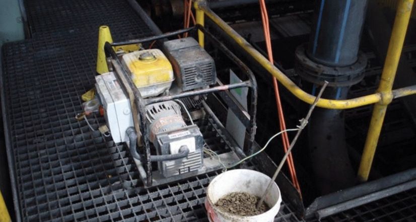
New text
                                                                                Deleted text
                                                                                Comment
                                                                                General
                                                                                Reference

THIS DOCUMENT
                                                                                               AS/NZS 3000
This document serves the purpose of a summary of changes set to come out with
the release of the revised standard AS/NZS 3000. Please note that these are
paraphrased descriptions and sentences may vary to the impending release. All
information was supplied and worded by a member of the standards committee
responsible for these changes, therefor, although this may not be a direct replica,
all educational information is accurate as dated to the most recent draft. All
information is to give a general guide as to the changes coming.

                                                                                               5.
SECTION ONE
              SCOPE, APPLICATION AND FUNDAMENTAL
              PRINCIPLES
              Standard description — This Standard sets out requirements for the design,
              construction and verification of electrical installations, including the selection and
              installation of electrical equipment forming part of such electrical installations.

              These requirements are intended to protect persons, livestock, and property from
              electric shock, fire and physical injury hazards that may arise from an electrical
              installation that is used with reasonable care and with due regard to the intended
              purpose of the electrical installation.

              In addition, guidance is provided so that the electrical installation will function
              correctly for the purpose intended and takes into account mitigating the
              foreseeable adverse effects of disruption to supply.

              1.1 Scope
              New paragraph added:
              In addition, guidance is provided so that the electrical installation will function
              correctly for the purpose intended and takes into account mitigating the
              foreseeable adverse effects of disruption to supply.
SECTION ONE

    6.
New text
                                                                                           Deleted text
                                                                                           Comment
                                                                                           General
                                                                                           Reference
1.4 Definitions
There are 28 new definitions added, 10 existing definitions revised and 1 definition
removed (duct). Definitions from Electricity Act or ESRs over-rule definitions in this
standard. Refer to ESR 4, paragraphs (2) and (4). The below are detailed examples
of some of these new/revised definitions, all of which will be noted in the new
standards for you to reference in the above noted section (1.4).

•   Accessible — Capable of being reached for inspection, maintenance or repairs

•   Readily Accessible — Capable of being reached quickly and without climbing over
    or removing obstructions, mounting upon a chair, or using a movable ladder; and
    in any case not more than 2.0 m above the ground, floor or platform.

•   Adjacent — Next to or adjoining without obstruction and in any case no more
    than 1.25M away (arms reach).

•   Alteration — An adjustment, change or modification to, or deletion or
    replacement of, a part(s) of an electrical installation.
    Note: Repairs are not alterations.

•   Repair — The work to restore the electrical installation to safe and sound
    working condition after deterioration or damage has occurred. Previously many
    references to ‘Alterations, additions and repairs’. All now classified as either
    ‘Alteration’ or ‘Repair’ because an addition is a type of alteration.

•   Normal supply — The source of supply that the electrical installation is supplied
    from under normal conditions of operation. Note: The normal supply is usually
    from a distribution network, but may instead be from a generation system.

•   Alternative supply — A supply system intended to maintain the functioning of an

                                                                                                          SECTION ONE
    electrical installation or a part or parts thereof, in case of interruption of the
    normal supply.

•   Supplementary supply — A supply system intended to operate in conjunction
    with the normal supply.

•   Electrical installation, residential — An electrical installation or that portion of
    an electrical installation associated solely with a living until or units. Example:
    Residential institutions, hotels, boarding houses, hospitals, accommodation
    houses or motels. Previously defined only with clause 2.6.3(RCDs); But now
    used in other clauses

                                                                                                          7.
•   Main switch — A device or devices, whos primary function is the isolation of
                  supply to the electrical installation by the customer. This device may also fulfill
                  regulatory requirements provided it is labeled accordingly. The key here is who is
                  expected to use the switch; e.g. meter isolators are NOT ‘mains switches’. Mains
                  switches are either at the main switchboard or at a DB where an alternative or
                  supplementary supply is connected.

              •   Arc fault detection device (AFDD) —A device intended to mitigate the effects of
                  arcing faults, within installation wiring and plug and lead connection of electrical
                  equipment, by disconnecting the circuit when an arc fault is detected.

              Some other definitions added to the most recent draft include:

              •   Electric vehicle

              •   Energized

              •   De-energised

              •   Live

              •   Fire mode

              •   Functional unit

              •   Lamp

              •   Lift

              •   Protective earth neutral (PEN)
SECTION ONE

              •   Socket outlet — Multiple combination

              •   Socket outlet RCD (SRCD)

              •   Soft wiring

              Some other amended definitions include:

              •   Authorised person

              •   MEN system

              •   Outbuilding

              •   Point (in wiring)

    8.
New text
                                                                                     Deleted text
                                                                                     Comment
                                                                                     General
                                                                                     Reference
•   Protective earthing conductor

•   Safety service

1.5.4.4 Protection by barriers or enclosures
The IP rating shall suit the environmental conditions and relevant mounting position
as specified by the manufacturer. This is the new requirement. Required degrees of
protection unchanged.

1.6.1 Design of an electrical installation
An electrical installation shall be designed to;

a) Protect persons, livestock and property from harmful effects;

b) Function correctly as intended;

c) Connect, operate safely and be compatible with the electricity distribution
system, or other source of supply, to which the electrical installation is to be
connected;

d) Facilitate safe operation, inspection, testing and maintenance;

e) Minimise reduce inconvenience in the event of a fault. NOTE: Consideration should
be given to the provisions of Appendix M concerning the disruption of supply.

1.7.2 Installation work practices
Requirement to clearly ID conductor function unchanged. Restriction on G, Y, & G/Y
colours for installation or sleeving (earthing only) unchanged. New restriction on
sheath colour:

f) Live conductors shall not be insulated or sheathed with green, yellow or green/

                                                                                                     SECTION ONE
yellow combination colours in installation wiring. NOTE: NZ exception added. Colour
does not matter.

i) Condensation issues — installation of breathing/pressure equalisation valve to
assist in changes in humidity and drainage of moisture.

j) Electrical equipment shall be installed to manufacturers instructions to ensure that
the marked IP rating is maintained.

The above is the first of several new rules requiring manufacturers instructions to
be followed. Previously manufacturers instructions were only mandated in Part 1.
Unless cable entries/breathers/drains are specifically allowed for by manufacturers
instructions, you must not drill a hole in an enclosure. The enclosure’s IP rating will be
destroyed. The use of a proper breather will be required in most cases.

                                                                                                    9..
1.9.4 Compliance by specific design
              Generally called ‘Part 1 solution’.

              1.9.4.6 Identification
              On the adoption of a ‘Part 1’ solution in relation to an electrical installation, the main
              switchboard of the installation where the ‘Part 1’ solution has been adopted, any
              other switchboard that is associated with the ‘Part 1’ solution, shall be clearly and
              permanently marked with the intent of the following words:

              ‘Warning: Part or parts of this installation adopt a ‘Part 1’ solution under AS/NZS
              3000 as shown in the documentation.’
SECTION ONE

    10..
New text
Deleted text
Comment
General
SECTION TWO
Reference
GENERAL ARRANGEMENT, CONTROL & PROTECTION
This Section specifies the minimum requirements for the selection and installation of
switchgear and control-gear that shall be achieved to satisfy Part 1 of this Standard.
2.1.2 Selection and installation
Switchgear and control-gear shall be selected and installed to perform the following
functions or have the following features:
f) Installed in accordance with the manufacturer’s instructions.
2.2 Arrangement of installation
2.2.1 Circuits
2.2.1.1 General
NOTE: Specific design and equipment may need to be considered to ensure the
continuity of supply. For further guidance, refer to Appendix M.
2.2.1.2 Origin of submains and final subcircuits
Every submain and every final subcircuit shall commence at a main switchboard or
at a distribution switchboard. All of the live conductors of one submain or one final
subcircuit shall commence at the one switchboard.
2.2.1.4 Electric vehicle charging circuits
Note: In Australia, guidance for installations for electric vehicle charging circuits is
SECTION ONE
provided in appendix P of AS/NZS 3000.
2.2.1.4 Electric vehicle charging circuits
Note: In Australia, guidance for installations for electric vehicle charging circuits is
provided in Appendix P. No clause, just a note; placed here because this is the logical
place where people would look. Labeled as ‘AU only’, but actually applies in NZ also.
Should also be a ‘NZ’ note pointing to clause 7.9.
2.2.2 Maximum demand
(c) Measurement — The maximum demand may be determined by the highest rate
of consumption of electricity recorded or sustained over a period of 15 30 minutes
when demand is at its highest by a maximum demand indicator or recorder.
11.2.3.2 Control
2.3.2.1.2 AC systems
Note: Warning regarding neutral connections. The manual disconnection and
connection of neutral conductors must be as follows:
• the active must be disconnected before the neutral
• the neutral must be connected before the actives
Refer to AS/NZS 4836 for safe work practices.
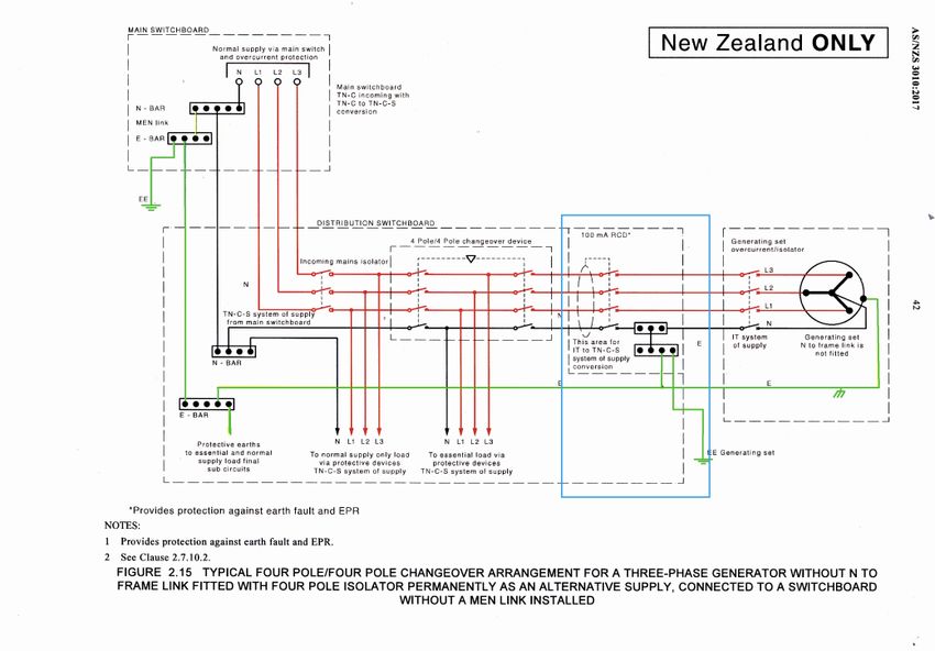
2.3.3Main switches
2.3.3 General
Where multiple supplies are provided, each supply shall be controlled by a
main switch or switches on the main switchboard for each supply. Exception:
Main switches for alternative or supplementary supplies may be located at any
switchboard within the installation, provided they are installed in accordance with an
applicable standard, for example, AS/NZS 3010 or AS/NZS 4777.1.
2.3.3.4 Location & Operation
(b) Main switches, operating handles or controls associated with such a main switch
shall be manually operated, single action, mechanical and shall consist of a handle,
lever, push buttons or similar device. Electronic touch screens, programmable
control systems or the like shall not be used as a means of operating main switches.
Electronic touch screens may be used for remote control of main switches as per
clause 2.3.3.6.
2.3.3.5 Identification
Main switches shall be identified as follows:
SECTION T WO
(e) Main switches for supplementary or alternative supplies shall be labeled to
indicate the energy source. Alternative supplies are those such as; solar/inverter
supply or generator.
2.3.3.6 Remote Control
(c) Where remote control facilities also provide the capability for a main switch to be
closed—
(iii) shall not be capable of being overridden or bypassed by programmable control
systems or the like.
(d) Where a touch screen, programmable control system or the like is used for the
remote control of one or more main switches the requirements for main switches as
per clause 2.3.3.4 (b) shall apply.
12.New text
Deleted text
Comment
General
Reference
2.5 Protection against overcurrent
2.5.1.2 Consumer mains
New explanation (with Fig) of what is, and isn’t, ‘unprotected consumer mains’. Not
relevant for NZ, because ESR 32 prohibits unprotected consumer mains.
Advice added to 4 Notes e.g. Note 2: An electricity distributor’s low voltage service
protective device may provide overload and short-circuit protection for consumer
mains and may satisfy Clause 2.5.5.3 under certain conditions. Negotiation with the
electricity distributor during installation planning stage is recommended. ESR 32
requires network to provide short circuit & fault protection for mains, but does NOT
require overload protection.
2.5 Overcurrent protection
All new Figs, plus 2 new; but no change to requirements.
2.5.7.2.3 General supply circuit discrimination
A number of changes to this clause, for example:
(a) 2 x circuit breakers
(iii) C2 (downstream) rated up to 250 A
Discrimination deemed to be provided where C1 (upstream) is > / = 1.5 x the
downstream breaker.
E.g. 63 amp MCB main switch and a 40 amp MCB sub mains
Current edition: 40 x 2 = 80
Now: 40 x 1.5 = 60
SECTION T WO
2.6 Additional protection by RCDs
What are RCDs are ‘additional’ to?
Note to 2.6.1 tells us ‘The use of RCDs is intended only to augment other measures
of basic protection’. Clause 1.5.4.2 lists acceptable methods of basic protection
(Insulation, barriers, Obstacles, Placing out of reach). RCDs are not listed, and are
specifically stated as: ‘not recognised as sole means of basic protection but may be
used to augment one of the above methods’.
13.1.5.6.2 tells us RCDs are recognised as a means of providing automatic
disconnection of supply i.a.w 1.5.5.3. So RCDs are:
• a complete method of fault protection; and
• Supplementary to accepted methods of basic protection
2.6.1 RCDs: General
Note 3 ( re 10 mA RCDs )
Suggested possible uses deleted; to avoid the advice being used in court as:
“Why didn’t you follow the recommendation in the Standard, Mr Sparky?”.
2.6.2 Selection & Arrangement
2.6.2.2 Types of RCD
Common belief that pretty much any RCD will do the job Increased use of high-
power electronics etc; means this is no longer true. Use of the wrong type of RCD
doesn’t just result in “nuisance tripping”. It can mean the RCD doesn’t trip when
it should. This doesn’t mean the RCD is “faulty” it means we need to learn how to
select an appropriate RCD for the circuit. There are (at least) 2 different groups
of “Types” of RCD. Types I, II, III, etc; classified by rated residual current- Specified in
AS/NZS 3190. Types A, AC, B, F, etc; classified by waveform reacted to. RCDs can
also be classified by trip time. Type I (max 10 mA). Both countries use Type I (fast
trip) for medical. NZ uses Type I (normal trip) for schools. Type II (up to 30 mA). Both
countries use Type II for general purpose. Currently Au uses Type AC (sine wave). NZ
uses Type A (sine wave + pulsing DC). Type III (up to 300 mA), sometimes used for
fire protection, likely to be required for fault protection of TT- supplied installations.
Type IV (up tp 300 mA, with built-in delay) RCDs used for fire protection only, may
be Type IV. High-power electronics may need Type F e.g. inverter supplies. EV
chargers will generally need Type B.
SECTION T WO
2.6.3 Locations where RCDs are required
Completely re-written; with different structure (and new heading). Originally as one
common clause for both countries (with separate non-domestic subclauses). Then
Au backed away from a couple of key provisions, so now only the introduction is
common.
2.6.3 Locations where RCDs are required - overview
2.6.3.1 General
Establishes how this clause fits with other RCD requirements.
2.6.3.2 Installation requirements – Australia
10.
14..New text
Deleted text
Comment
General
Reference
• 2.6.3.2.1 Domestic & Residential
• 2.6.3.2.2 Non-Domestic & Non-Residential
• 2.6.3.2.3 Home care installations
• 2.6.3.2.4 Alterations to installations and replacement of switchboards
• 2.6.3.2.5 Repairs
2.6.3 Locations where RCDs are required - overview
• 2.6.3.3 Installation requirements – New Zealand
• 2.6.3.3.1 Residential installations
• 2.6.3.3.2 Non-residential installations
• 2.6.3.3.3 Home care installations
• 2.6.3.3.4 Additions and alterations
2.6.3.1 General
The requirements of this Clause for the installation of RCDs are in addition to the
RCD requirements for electrical installations as specified in :
(a) other Australian and New Zealand Standards, e.g. AS/NZS 3001, AS/NZS 3002,
AS/NZS 3003, AS/NZS 3004, and AS/NZS 3012.
The requirements of this Clause for the installation of RCDs are in addition to the
RCD requirements for electrical installations as specified in :
SECTION T WO
(b) other Sections of this standard, e.g.
(i) Section 3 for protection against mechanical damage;
(ii) Section 6 for baths, showers and other water containers; and
(iii) Section 7 for specific electrical installations; and
(c) the requirements and regulations of legislation, such as Occupational Health and
Safety Legislation. Note: In New Zealand, attention is drawn to the requirements of
NZECP 55 for wiring and fittings located near conductive thermal insulation.
15.2.6.3.3.1 Residential installations – New Zealand
No change to clause.
Subcircuits supplying:
- sockets, lights, and hand-held equipment.
Change to “all final subcircuits” had been intended (for both countries) dropped due
to increased cost (politics). May happen in Amendment 1.
Some Exceptions deleted:
Home Dialysis - not needed; the provisions are cumulative; If it’s both “residential” &
“Home care”; then BOTH rules apply. Alterations & Repairs - Not needed; provisions
are alternative; It’s either a new subcircuit or it’s an existing one.
New Exception added:
This requirement need not apply to a final subcircuit for which a method of fault
protection other than automatic disconnection of supply is applied, e.g. a separated
supply in accordance with Clause 7.4 or supply at extra low voltage in accordance
with Clause 7.5. New; needed because pointless to install an RCD for ELV or
separated supply.
Exception for ranges remains. New note clarifies that the rule only applies to
complete new subcircuits, not to additions or alterations.
2.6.3.3.2 Non Residential installations – New Zealand
(used to be “other” installations)
In New Zealand, the following requirements apply to nonresidential locations:
(a) Education and childcare facilities
(b) Junior education and childcare facilities
(c) Other Locations
SECTION T WO
(d) Particular types of equipment
(a) Education and childcare facilities
Additional protection by an RCD with a maximum rated residual current of 30 mA
shall be provided for final subcircuits supplying one or more socket-outlets having a
rating not exceeding 30 A in—
(i) kindergartens;
(ii) day care centers for preschool children;
(iii) schools for children up to and including school Year 13; and
(iv) areas in tertiary education or vocational training facilities that are primarily used
or intended for teaching or training.
16.New text
Deleted text
Comment
General
Reference
(b) Junior education and childcare facilities
Additional protection by an RCD with a maximum rated residual current of 10
mA shall be provided for socket-outlets in areas within a building primarily for the
purpose of teaching or caring for children in—
(i) kindergartens;
(ii) day care centers for preschool children; and
(iii) schools for children up to and including school year eight.
Note: these RCDs need not be Type I as used for electrical medical devices
(c) Other Locations
Socket-outlets with a rating not exceeding 30 A, and supplies to directly connected
hand-held equipment, installed in the following locations, shall be protected by RCDs
with a maximum rated residual current of 30 mA:
(i) Outdoor locations.
(ii) Locations that have easy or unsupervised public access. Note: Typical examples
include public areas of train stations, airports and shopping malls
(iii) Amusement arcades.
(iv) Sockets in damp situation zones
(d) Particular types of equipment
Socket-outlets for and supplies to the following types of equipment shall be
protected by RCDs with a maximum rated residual current of 30 mA:
(i) Children’s rides.
(ii) Vending machines.
Exception 1:
SECTION T WO
The requirements of Items (a), (b), (c) and (d) need not apply to the following:
Where other methods of fault protection other than automatic disconnection of
supply are applied, e.g. a separated supply in accordance with Clause 7.4, or supply
at extra low voltage in accordance with Clause 7.5. Where the disconnection of a
circuit by an RCD could cause a danger greater than earth leakage current. Where
socket outlets that are part of a mining operation are supplied at reduced low
voltage.
Exception 2:
The requirement of Item (b) for additional protection by 10 mA RCDs need not apply
to the following:
Socket-outlets mounted above 1.8 m from the floor or above 1.8 m from a platform
that is accessible to children. Socket-outlets specifically for the supply of electricity
to information technology equipment or cleaning equipment that are clearly
marked to indicate the restricted purpose of the socket outlet and that 10 mA RCD
protection is not provided.
17.Socket-outlets in corridors, halls, gymnasiums and similar areas where portable
electrical appliances are not likely to be used by children.
Areas occasionally used by children up to school year eight but primarily intended
for the care or education of older age groups.
A socket-outlet or a connecting device specifically for the connection of a fixed or
stationary electric cooking appliance, such as a range, oven or hotplate unit provided
that;
• the socket-outlet is located in a position that is not likely to be accessed for
general purposes;
• the socket-outlet is clearly marked to indicate the restricted purpose of the
socket-outlet; and
• the socket is supplied by a dedicated circuit protected by a 30 mA RCD.
Repeats the exception for residential.
Notes:
Childcare facilities include any premises registered with local authorities as a
day-care centre and or registered or licensed family day-care premises. Where
one clause requires 30 mA RCD protection of the final subcircuit, and this Clause
requires 10 mA RCD protection of the socket-outlet; a RCD at the switchboard and
a 10 mA RCD in the same room as, or incorporated into, the socket-outlet(s) would
satisfy both these requirements. Care should be taken to avoid nuisance tripping by
limiting the number of socket-outlets protected by the same 10 mA RCD.
Reduced low voltage means either—
(a) a single-phase system in which— he nominal line-to-line voltage does not exceed
110 volts a.c.; and the nominal line-to-earth voltage does not exceed 55 volts
SECTION T WO
a.c.; and all exposed conductive parts are connected to the protective earthing
conductor; Or
(b) a three-phase system in which— the nominal line-to-line voltage does not
exceed 110 volts a.c.; and the nominal line-to-earth voltage does not exceed 63.5
volts a.c.; and all exposed conductive parts are connected to the protective earthing
conductor.
.
18.New text
Deleted text
Comment
General
Reference
2.6.3.3.3 Home care installations – New Zealand
The installation of medical electrical equipment in home care medical installations
shall comply with AS/NZS 3003. No longer just “Home dialysis”; includes other kinds
of treatment. No special rules set by “3000”, so always keeps in step. “Electrical
medical device” is defined in ESRs ; & ESR 60 requires ANY location intended for use
with EMDs to comply with “3003”.
Notes:
• Some of these installations require a Type I RCD, with a maximum rated residual
current of 10 mA and faster tripping time.
• Further information on reliability of supply is provided in Appendix M.
“3003” has been revised. Current edition (not yet cited) covers “home care”. Latest
edition, when cited, will also cover use of portable RCD for travellers.
2.6.3.3.4 Additions and Alterations – New Zealand
The following shall apply:
(a) General - Where all of the circuit protection on a switchboard is replaced,
additional protection by RCDs as required by this clause (Clause 2.6.3) shall be
provided for the final subcircuits supplied from that switchboard.
(b) Socket-outlets - Socket-outlets added to an existing circuit shall be protected
by an RCD in accordance with the requirements for new subcircuits in the part of
the installation in which the sockets are located. Where socket-outlets are added to
an existing final subcircuit and RCD protection of the subcircuit is required, installing
the RCD at the origin of the subcircuit is preferred, however the RCD protection
need only be fitted at the commencement of the additional wiring. The location of
all such RCDs should be recorded at the switchboard from which the final subcircuit
originates.
SECTION T WO
Exception for replacing existing sockets remains.
Exception for lighting points added removed - not needed.
Exception for where a new subcircuit wouldn’t need an RCD remains.
2.9 Protection against arc faults
2.9.1 General
Protective devices such as arc fault detection devices (AFDDs) may be used to
protect against the effects of arc faults for final subcircuits, especially—
a) in premises with sleeping accommodation;
b) in locations with risks of fire due to the nature of processed or stored materials,
(e.g. barns, wood-working shops, stores of combustible materials);
c) in locations with combustible construction materials, e.g. wooden buildings; and
d) in fire propagating structures. (See Appendix O for more details).
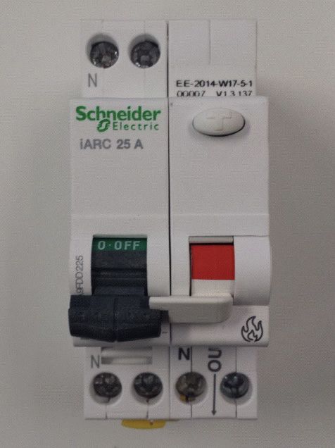
19.AFDDs
• monitor & react to disturbances in the
waveform caused by arcing faultsSwitch active(s) & neutral
• Have a test button
• May incorporate an RCD function (eg 300 mA)
• Can have other functions e.g. combi AFDD + overcurrent
Where AFDDs are installed, the provisions of Clauses 2.9.2 to 2.9.4 shall apply.
NOTE: The use of AFDDs does not obviate the need to apply any other measures
required by other clauses in this standard.
2.9.2 Type
AFDDs shall comply with IEC 62606.
2.9.3 Rating
AFDDs shall have a load current rating no less than that of the associated circuit
protective device.
2.9.4 Arrangement
AFDDs shall be located at the switchboard from which the final subcircuit being
protected originates.
2.9.5 Alterations
The installation of AFDDs should be considered when carrying out alterations to final
subcircuits in situations where existing wiring systems may significantly deteriorate.
Notes:
SECTION T WO
Further guidance on AFDDs is provided in Appendix O. AFDDs may be used to
supplement protection of aged wiring. Deterioration of circuits may include damage
by vermin.
2.9.7 Final subcircuits in New Zealand
In New Zealand, all final subcircuits having a rating not exceeding 20 A supplying the
following shall be protected by an AFDD:
Note: When considering possible deterioration of circuits, circuits passing through an
area should be considered as well as those supplying equipment within the area.
20.New text
Deleted text
Comment
General
Reference
Mandatory AFDD for:
a) Points in locations with the risk of fire due to the nature of processed or stored
materials, e.g. barns, woodworking shops and stores of combustible materials.
b) Points in locations containing irreplaceable items.
c) Points in historic buildings constructed largely of flammable materials.
d) Final subcircuits supplying socket-outlets in school dormitories.
2.10 Switchboards
2.10.1 General
A switchboard or switchboards shall be provided in an electrical installation for the
mounting or the enclosure of switchgear and protective devices.
New exception for teeing-off eg submains to a switchboard; using smaller cable
for the branch but without having to place the overcurrent protection within a
switchboard:
If protection not fitted at tee-off:
Fault protection in place for the smaller conductors
• Length not exceed 3 m
If protection fitted at Tee-off:
• Fault protection in place for the smaller conductors
• Max 2 protective devices per phase, else deemed to be a switchboard
2.10.2.2 Accessibility and emergency exit facilities
Sufficient access and exit facilities shall be achieved by the provision of the following:
(i) 1.0 m minimum from all faces of a closed switchboard that need to be accessible
(ii) Unimpeded space of at least 0.6 m around switchboards with switchgear doors
SECTION T WO
in any position and with switchgear in a fully racked-out position.
(iii) A minimum of two emergency exit paths, spaced well apart, where a
switchboard—
(a) is rated as a circuit with a nominal capacity of not less than 800 A per phase; or
(b) is more than three metres in length.
Exception:
Where a clear space of at least 3 m is provided between the emergency exit path
and the switchboard and its equipment, including switchboard doors, in all normal
positions of operating, opening and withdrawal, only one emergency exit path need
be provided.
21.(iv) Openings or doorways that are at least 0.9 m wide by 2.2 m high to allow
persons necessary access to the switchboard room or enclosure.
Currently: 0.75 m wide 1.98 m high. All Figs revised to illustrate the new required
dimensions.
Note: There is NO Exception for domestic, so if you haven’t got 1.0 m from closed
face, and 0.6 m from open door, the switchboard can’t go there.
2.10.2.5 Restricted locations
(k) Hazardous areas
New Fig 2.24 copy of Fig 4.10 (gas bottle “cone” Zone )
New Note, pointing to Fig 4.11 (reticulated gas regulator zone )
2.10.3.2 Suitability
Switchboards shall be suitable to withstand the mechanical, electrical and thermal
stresses that are likely to occur in service, and the environment in which it is
to be installed. Switchboards complying with the relevant requirements of the
AS/NZS 3439 or AS/NZS 61439 series of Standards are considered to meet
the requirements of this Clause. Appendix K provides recommendations and
requirements on the relevant design verification and validity tests applicable to
switchboards complying with AS/NZS 61439 series.
2.10.3.4.2 Location of fuses and circuit-breakers
Fuses and circuit breakers shall be located in the following ways:
a) Grouping:
Fuses and circuit breakers shall be grouped in such a manner as to indicate their
relationship to each other, e.g. equipment—sump pump motor.
b) On the back of switchboards or behind switchboard escutcheons
Fuses or circuit breakers shall not be fixed on the back of, or behind, a switchboard
panel, frame or escutcheon.
SECTION T WO
Exception 1:
Fuses used for the following purposes may be fixed on the back of or behind, a
switchboard panel, frame or escutcheon:
Used solely as a fault-current limiter; or.
Used to protect instruments or control equipment on the switchboard.
Exception 2:
Circuit breakers may be fixed on the back of, or behind, a switchboard panel
frame or escutcheon — provided that they may be operated from the front of the
switchboard panel frame or escutcheon; or if used solely as a fault-current limiter;
or if used to protect instruments or control equipment on the switchboard.
22.New text
Deleted text
Comment
General
Reference
2.10.4.3 Neutral Bar or Link
New paragraph added:
Where a cable is used as the neutral conductor, and is looped between devices on
the line side, the connection to each device shall be such that continuity remains
when the device is removed. Twisting of conductors is not adequate.
SECTION THREE
SELECTION & INSTALLATION OF WIRING SYSTEMS
3.3 External influences
3.3.2.13 Thermal insulation
Where cables pass through bulk thermal insulation, they shall be rated for current-
carrying capacity, in accordance with the AS/NZS 3008.1 series, as follows:
Length of cable passing through insulation:
(a) 150 mm to 400 mm—use ‘partially surrounded’ rating;
(c) >400 mm—use ‘completely surrounded’ rating.
Note: In New Zealand, attention is drawn to the requirements of NZECP 55 for wiring
and fittings located near conductive thermal insulation. ECP 55 (Foil) is not yet cited
SECTION THREE
by ESRs, but should be followed.
3.8.1 General
Paragraph 3
Conductors with green, yellow or green/yellow combination coloured insulation or
sheathing shall not be used as active or neutral conductors in installation wiring.
Exception:
In New Zealand, there is no restriction on sheathing colour.
23.3.8.2.2 Sleeving of existing earthing and bonding conductors
In electrical installations where earthing or bonding conductors have been previously
installed using bare or green conductors, complying with previous editions of this
standard, then those earthing or bonding conductors can still remain for their
intended use.
When alterations, additions or repairs are carried out, that
result in new terminations or junctions to those existing bare or green conductors,
then all the bare or green coloured conductors shall be sleeved with green/yellow
sleeving within each of those new cable junctions or terminations.
3.8.2.3 Sleeving of existing live conductors
In electrical installations where conductors with yellow insulation have been
previously installed as live conductors, complying with previous editions of this
Standard, such conductors with yellow insulation can still remain for their intended
use. When alterations, additions or repairs are carried out that result in new
terminations or junctions to those existing live conductors with yellow insulation, such
live conductors with yellow insulation shall be sleeved with white sleeving within each
of those new cable junctions or terminations.
3.9.3.3 Wiring systems likely to be disturbed
Split into two subclauses
3.9.3.3.1 Locations
No change
Wiring systems that are likely to be disturbed.
3.9.3.3.2 Support & protection
Wiring systems installed in positions where they are likely to be disturbed shall be—
(i) supported at suitable intervals to prevent the undue sagging of cables;
SECTION THREE
(ii) supported to prevent accidental withdrawal of cables from electrical equipment
exposing single-insulated conductors ; and
(iii) protected from impact as specified in Clause 3.3.2.6. RCDs shall not be used in
lieu of mechanical protection for this clause.
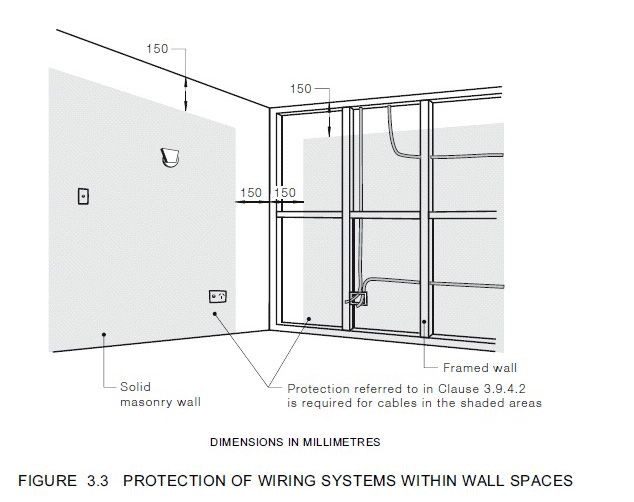
3.9.4.2 Wiring systems near building surfaces
Wiring within 50 mm of surface must be either protected; or free to move to > 50
mm; even if within 150 mm of wall / wall or wall / ceiling corners (same as anywhere
else - current “free zone” along top of wall & down corners removed.)
24.New text
Deleted text
Comment
General
Reference
Old Fig explaining the 150 mm corner zone deleted.
Protection now req’d even within
150 mm of ceiling
SECTION THREE
Protection now req’d even within
150 mm of corner
25.3.9.4.2 Wiring systems near building surfaces
If equipment holds cables within 50 mm of surface. Protection may be required
both in front and / or at rear of equipment - eg switchboards, esp. entry points.
Plastic switchboard may need metallic panel behind to prevent screws penetrating
rear & damaging conductors.
3.9.8.2.1 Common enclosure/cable.
Conductors for the following applications shall not be installed within the same pipe,
tube, conduit or the same multi-core cable:
(a) conductors that form part of different electrical installations;
(b) conductors that form part of individual occupancies of single or multiple electrical
installations.
Exception for cable tray / duct with removable / no cover / lid.
3.11 Underground wiring
3.11.4.4 Minimum depth of cover
Where cables are buried close to a sloping or vertical surface, these dimensions
shall also apply perpendicular to that surface. Figs updated to include references to
tables & clauses.
SECTION THREE
26.New text
Deleted text
Comment
General
Reference
SECTION FOUR
SELECTION & INSTALLATION OF APPLIANCE
& ACCESSORIES
4.1.3 External influences
New Notes:
NOTE 2: Purpose made anti-condensation and water drains that maintain the IP
rating of the enclosure may be used.
NOTE 3: Drilling a drain hole in the bottom of the enclosure alone destroys the IP
rating of the enclosure.
New rule for soffits & other overhangs
Electrical accessories not having any specific degree of protection marked on
the product is considered as being protected from the weather when installed
within the space contained by the soffit (the edge of the eave, veranda or similar
overhang) and a plane from the outer edge of the soffit, at an angle of 30 degrees,
continuing to the exterior wall.
Electrical accessories installed outside that area shall have a minimum degree of
protection of IP33. Refer to Figures 4.1 and 4.2.
Exceptions:
Meter box enclosures within the area need not comply but shall still be required
to have a minimum degree of protection of IP2X and shall still be required to be a
minimum of IP23 outside that area; or greater if required by the local service rules.
Electrical accessories, not having a specific degree of protection marked, which are
SECTION FOUR
contained within meter box enclosures need not comply.
Fig 4.1
Side view of overhang e.g. eave / deck
Above 30 deg line;
accessories deemed
protected .˙. No IP Rating
Below 30 deg line;
P 33 minimum required
27.Fig 4.2
Front-on view of eave / deck
Above 30 deg line;
accessories deemed protected
Below 30 deg line;
IP 33 Overhang must be continuous;
for slatted deck, each slat creates a separate (tiny) protected zone.
4.3.3 Installation wiring connected via an installation couplers
SECTION FOUR
New clause for “Soft wiring”
4.3.3.1 General
Cords or cables connected by means of an installation coupler shall be
a) of heavy-duty sheathed type complying with AS/NZS 3191 and the requirements
of Clause 3.9.7.4 or AS/NZS 5000 ;
b) selected to suit the protection device;
Exception:
For sections of installation wiring that terminate within a single piece of electrical
equipment, such as a luminaire, single socket-outlet or SELV socket-outlet, the cable
may be reduced to suit the rating of that single piece of electrical equipment.
28.New text
Deleted text
Comment
General
Reference
c)adequately protected and installed to minimize the risk of mechanical damage in
accordance with Clause 3.3.2.6;
d)supported and fixed in position in accordance with Clause 3.3.2.8 and Clause
3.9.3.1; and
e) as short as practicable.
4.3.3.2 Arrangement
Refers to the use of Heavy Duty sheathed flexible cords or cables to AS/NZS 3191
and AS/NZS 5000.
Exception:
For sections of installation wiring that terminate with a single piece of electrical
equipment, luminaire or socket-outlet, the cable may be reduced to suit the rating
of that single piece of electrical equipment.
4.3.3.3 Socket-outlets for these systems
Socket-outlets supplied by these systems shall meet the following requirements:
(a) The socket-outlet shall be suitable for the intended application and comply with
Clause 4.4.
(b) The socket-outlet shall be secured in position and installed in accordance with
Clauses 4.4.2.1 and 4.4.2.2.
(c) When installed on a horizontal surface, socket-outlets shall be designed or
arranged to prevent the accumulation of dust or water in accordance with clause
1.5.4.
(d) Where installed in a location that is not readily accessible, the socket-outlet shall
be securely fixed to a structure or support to ensure that no mechanical strain is
placed on the installation wiring connections when inserting or removing a plug from
the socket-outlet.
4.3.6 Equipment Wiring
New paragraph (e)
SECTION FOUR
Installation wiring connected within a luminaire or passing through a luminaire shall
be so selected and erected that they will not suffer damage or deterioration due to
heat or UV radiation generated by the luminaire or its lamps.
29.4.4 Socket-outlets
4.4.1.1.2 Socket-outlets – Alternative pin configurations
Socket-outlets with alternative pin configurations e.g. UK, French, German and USA
types, shall be used only under the following conditions:
(a) The socket-outlet shall have a single set of apertures with an earthing contact
and comply with the national standard of the country, as shown in IEC/TR 60083.
Socket outlets with a single set of pin apertures that accept multiple alternative pin
configurations shall not be used.
Exception:
Shaver socket outlets complying with AS/NZS 3194.
(b) The installation of the socket-outlet shall comply with Clause 4.4.4.
(c) The socket-outlet shall be rated at the voltage of the electrical installation, unless
supplied at a lower voltage, in which case it may be rated at that lower voltage.
(d) Socket-outlets with alternative pin configurations normally supplying a voltage
less than that of the electrical installation shall be supplied at that lower voltage.
(e) The socket-outlet shall have been tested to the equivalent of the requirements
of the Standards listed in Clause 4.4.1.1.1 (a), (b), (c) and (d).
In New Zealand only, the following additional provisions apply:
(f) socket outlets with alternative pin aperture configurations shall be used only in:-
(i) facilities directly associated with an international airport;
or
(ii) residential areas of non-domestic electrical installations providing
accommodation for international visitors or guests.
(g) Socket-outlets with alternative pin configurations detailed in IEC TR 60083 as
requiring a nominal voltage of 230 volts supply, shall be protected by a RCD with a
maximum rated residual current of 10 mA and by an AFDD.
Notes:
SECTION FOUR
These RCDs need not be Type 1 as used for electrical medical devices.
Requirements for installation of AFDDs are in Clause 2.9, and further guidance is in
Appendix O
(h) Socket-outlets with alternative pin configurations detailed in IEC TR 600083
as requiring a nominal voltage of 110 volts supply shall be supplied at Reduced low
voltage.
Note:
Reduced low voltage is defined in Clause 2.6.3.3.2
ALL sockets are DMRAs (requiring SDoC; ESR 83) and DHRAs (Requiring Approval;
ESR 84). Approved ‘foreign’ type sockets can be installed in hotels & airports but
multi-fit sockets are banned, apart from the exception for shaver units.
30.New text
Deleted text
Comment
General
Reference
4.4.1.1.3 Low voltage fixed socket outlet
A low voltage fixed switch or socket-outlet, or its faceplate, shall not incorporate
a connecting device for telecommunications, data, television, radio or other similar
wiring systems.
NOTE: USB charging socket-outlets on the faceplate are acceptable as the are
fed from the LV system. Aerial and communications’ systems are all ELV systems,
providing a dangerous situation if the are inadvertently livened.
4.4.1.3 Socket-outlets for electric vehicle charging
Information for the installation and location of socket-outlets for electric vehicle
charging stations is provided in Appendix P
4.4.1.3.1 Electric vehicle charging socket outlets for NZ
In New Zealand only, requirements for the installation and location of socket-outlets
for electric vehicle charging stations are provided in Clause 7.9.
4.5.1 Lampholders, including lampholders incorporated in a luminaire
4.5.1.1 Location
All lampholders shall be located to be adequately protected against damage that
might reasonably be expected. In order to protect against inadvertent contact with
live parts, low voltage lampholders shall be located to minimize the risk of—
(a) direct contact with live parts of a lampholder when the lamp is removed; and
(b) mechanical damage to the lamp or lampholder. “In a luminaire” deleted from
deemed-to-comply list. “Cordgrip” pendants & batten holders always had to be
above arm’s reach. The “OK in a luminaire” concept was intended for luminaires
with a cover over the lamp. It stopped working when a set of batten holders
was mounted on a bar, and thus met the definition of “luminaire” ;despite having
accessible live parts. No more “Hollywood’”lighting bars with bare lamps.
SECTION FOUR
4.5.2.3 Recessed luminaires
4.5.2.3.2 Warning sign
Where recessed luminaires are installed in an accessible roof space, a permanent
and legible warning sign shall be installed in the roof space adjacent to the access
point, in a position that is visible to a person entering the space. The sign shall
contain the words shown in Figure 4.11 with a minimum size of lettering of 10 mm.
Exception: Where all recessed luminaires installed in an accessible roof space are of
either IC or IC-4 classification the warning sign is not required.
31.4.5.2.3.3 Installation
The installation rules have been completely re-written but not much real change (for
NZ).
New rules for recessed lighting
(i) Suitably designed and certified recessed luminaires have installation
classifications and shall be marked accordingly. The manufacturer’s instructions shall
provide all details in regard to restrictions for installation in certain applications.
(ii) Unmarked light fittings shall be treated as ‘Do Not Cover’. For these typical
fittings, the installation method shall be to provide barriers [compliance method
4.5.2.3.1(ii)] or clearances [compliance method 4.5.2.3.1(iii)] during installation, so as
to prevent contact with materials that may impede air flow (e.g. thermal insulation)
or that may be affected by the high tempture (e.g. combustible building elements
and insulation).
(iii) Where building insulation is already fitted and recessed luminaires are
retrofitted, added or altered, precautions shall be taken by the luminaire installer
not to compromise the safety of the installation.
Current NZ “default” clearances remain; now used in AUS also.
SECTION FOUR
32.New text
Deleted text
Comment
General
Reference
4.5.2.3.4 Classifications of recessed luminaires
New system; based on the system NZ has been using for last few years. System
defined in AS/NZS 60598.2.2, Appendix ZZ but“3000” includes enough info so
you’ll know what to do. All the labels, and some of the classifications, have changed.
Old style labels can be used until Feb 2018. Once new edition is cited, can only use
old stock for repair or replacement. New installation must use fittings with new
classifications & labelling.
Cannot be abutted against or covered by
normally flammable materials or used in
installations where building insulation or
debris are, or may be, present in normal use.
NOT allowed for residential installations. NON IC
Can be used where normally flammable
materials, including building insulation,
are, or may be, present, but cannot be
abutted against any material and cannot
be covered in normal use. Shall NOT be
installed in residential installations.
DO NOT COVER
Can be abutted against normally flammable
materials, including building insulation, but
cannot be covered in normal use. Building
elements, building insulation or debris have
limited access to the heated parts of the luminaire. CA 90
(New Zealand only) can be abutted against
normally flammable materials, including building
insulation. Building elements, building insulation
or debris have some access to the heated
CA 135
SECTION FOUR
parts of the luminaire.
Can be abutted against normally flammable materials, i
ncluding building insulation, and can be covered in normal
building elements, building insulation or debris have
limited access to the heated parts of the luminaire. IC
33.Can be abutted against normally flammable
materials, including building insulation, and can
be covered in normal use. Building elements,
building insulation or debris have restricted
access to the heated parts of the luminaire.
This classification of recessed luminaire is
effectively a sealed unit that has a restricted IC 4
flow of air between the habitable room the
luminaire emits light into, and the void/space
where the main body of the luminaire is located.
4.3.2.3.5 Requirements for specific classifications
Non-IC lminaires shall not be installed in residential buildingsinstallations. In New
Zealand only, Do not cover luminaires shall not be installed in residential installations.
Only recessed luminaires of classifications Do Not Cover, CA90, CA135 (NZ only),
IC or IC-4, which are compliant with AS/NZS 60598.2.2, Appendix ZZ, shall be
installed in residential buildings. Table 4.3 provides information and guidance on the
classifications, symbols, applications and general restrictions on recessed luminaires.
4.7.3 Clearance from open cooking surfaces
Socket-outlets and switches shall not be installed in the prohibited location shown
in Figure 4.17, on any wall, cupboard or other surface within 150mm of the edge of
an open gas or electric cooking surface, in the area extending from the top of the
cooking surface to a range hood, cupboard or ceiling located directly above the
cooking surface, or 2.5m above the floor that is directly below the cooking surface,
whichever is the lower.
Accessories Prohibited near
gas or electric hob
SECTION FOUR
- within 150 mm horizontal”
from hob edge
- from hob surface to
obstruction above
- if no obstruction, to 2.5 m
above floor
34.New text
Deleted text
Comment
General
Reference
4.8.2.3 Water heater isolating switch
New (b):
Installed adjacent to but not on the water heater.
Can no longer use the mcb at swbd as means of isolation.
PCUs & similar are NOT isolating switches
Where a water heater is supplied by two or more final subcircuits, all of the final
subcircuits for that water heater shall be capable of being isolated by a single
isolating switch e.g. controlled & uncontrol circuits: same switch.
4.10.2 Heating Cables
In New Zealand only, in-floor and ceiling heating cables shall be installed in
accordance with NZS 6110.
4.12 Electricity converters
Includes inverters, UPS & VFDs
4.12.5.2.2 RCDs
The possible waveform of a fault current to earth can affect the operation of
RCDs and shall be taken into account for the selection of the type of RCD. Where
an electricity converter includes an inverter, the RCD shall be of a type suitable
for the waveform of the particular inverter, and in accordance with the inverter
manufacturer’s recommendations.
4.18 Gas appliances & Equipment
4.18.2.2 Hot particles and surfaces
Refer to clause 7.7 and AS/NZS 60079.14 for exclusion zones in hazardous areas.
60079.14 clause 6.2.6 prohibits anything within 3.5 m above a zone that may cause
hot particles to drop into a hazardous area zone.
SECTION FOUR
4.18.2.3 Electrical equipment and gas supply—NZ only
In New Zealand domestic installations only, only electrical equipment that is directly
associated with the gas supply may be installed in the exclusion zone shown in
Figure 4.18. Not really a new rule, because ESRs citation changed the current rule to
this.
35.But now apply new “3.5 m above” rule:
No unenclosed lamps, etc for 3.5 m above
zone. Also: Remember the “Cone Zone”
also applies to small bottles e.g.
on caravans - just shorter.
4.18.4 Gas relief vent terminal
Electrical equipment that is a source of ignition, such as socket-outlets, switches,
luminaires, switchboards, meter boxes and airconditioners, shall not be installed
within the hazardous areas shown in figure 4.19 for gas relief vent terminals.
4.19 Air Conditioning & Heat Pump systems
New rule:
For airconditioning systems where the internal head unit (s) are supplied from a
circuit separate to that of the compressor, a warning sign shall be permanently
SECTION FOUR
fixed on or adjacent to the compressor isolator indicating that the isolator does not
isolate the ancillary equipment. Where the head unit is not connected by plug and
socket an independent isolating switch in accordance with Clause 2.3.2.2 shall also
be installed adjacent to each separately supplied head unit.
Heat pump switches that are not “isolating”. Switches are installed routinely e.g.
PDL’s WP series. The symbol indicated in 2.3.2.2 must be on the approved isolators.
New exception added:
Unitary window or through-wall air conditioners, nor to heat pump hot water
services, that are supplied supplied by plug and socket adjacent to unit.
36.New text
Deleted text
Comment
General
Reference
4.20 Lifts
A clause is now included to for lifts that are not safety services.
7.2.1.1 General
These requirements are intended to ensure that electricity supply is not
inadvertently disconnected from electrical equipment that is required to operate
during emergency conditions.
ALL lifts must comply with this new clause and lifts that are safety services must
also comply with clause 7.2.
Lifts are increasingly required to remain operational during emergencies, including
fires, especially in very tall buildings. Fire service may need to use a lift to get
equipment to the fire or to evacuate disabled people. Neither NZ Building Code, nor
standards for lifts cited by it have caught up with this concept. Confirmation may
need to be sought before installing a lift.
4.20.1 General
The electrical installation of lifts shall be installed in accordance with the appropriate
requirements of this Standard. These lifts include but are not limited to:
(a) Electric lifts
(b) Electrohydraulic lifts
(c) Goods Lifts
(d) Motor Room-less Lifts (MRLs)
(e) Passenger lifts
Lifts shall be installed in accordance with the New Zealand Building Code. Lifts that
are installed as emergency lifts, shall comply with the additional requirements for
Safety Services in clause 7.2.
NOTE: Regulatory authorities may have additional requirements.
Regardless of whether they are “emergency lifts”, ALL lifts are “specified systems”
under NZ’s Building Act, and must be inspected and maintained under the BWOF
SECTION FOUR
system. Unlike normal wiring work, specified systems require building consent for
installation or alteration of wiring.
4.20.2 Lift supply arrangement
Lifts shall be supplied by a dedicated circuit.
4.20.3 Labelling
Lift circuits shall be clearly identified by contrasting colouring or other suitable
means, in accordance with Clause 2.3.4.4.
WARNING: LIFT CIRCUIT- DO NOT SWITCH OFF.
37.4.20.4 Motor room-less lifts (MRLs)
4.20.4.1 General
Lifts classified as motor room-less lifts (MRLs) are lifts that due to their design have
no need for a traditional lift motor room. MRLs that are installed as emergency lifts
shall comply with the additional requirements for safety services in Clause 7.2.9.
4.20.4.2 MRL Switchboards
An MRL switchboard shall not be located in the lift shaft.. A switchboard located
remote from the main switchboard and dedicated to supplying individual MRL
switchboards shall be readily accessible.
4.20.4.3 Switchgear
The protective and control device(s) of an MRL shall be located in a readily
accessible position.
SECTION FIVE
EARTHING ARRANGEMENTS
& EARTHING CONDUCTORS
5.1.3 MEN earthing system
Minor changes to description of system
- Clarifying how “MEN” fits into the IEC family of earthing systems
SECTION FIVE
- Recognising that the distribution “Neutral” is actually a “PEN” conductor
Protective Earth Neutral.
Getting closer to abandoning the longstanding AS / NZS “MEN” terminology, and
adopting IEC terminology. Basically what we know as “MEN” is just one among
several particular variants of “TN-C-S”
Terra Neutral - Common - Separate
Terra Neutral means the neutral is earthed
In the distribution system, the neutral and earth functions are common. Within the
installation, each has its own separate conductor.
38.You can also read