2020 Reverb Stealth C1 - SERVICE MANUAL - SRAM Service
←
→
Page content transcription
If your browser does not render page correctly, please read the page content below
2020 Reverb Stealth C1

SERVICE MANUAL

                   GEN.0000000006086 Rev A © 2019 SRAM, LLC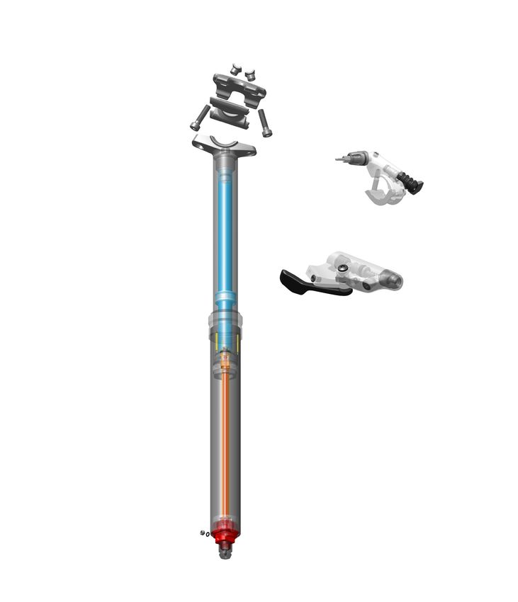
SRAM® LLC WARRANTY
EXTENT OF LIMITED WARRANTY
Except as otherwise set forth herein, SRAM warrants (i) Zipp® MOTO™ Rims to be free from defects in materials or workmanship for the lifetime of the
product, and (ii) its other products to be free from defects in materials or workmanship for a period of two years after original purchase. This warranty
only applies to the original owner and is not transferable. Claims under this warranty must be made through the retailer where the bicycle or the
SRAM component was purchased. Original proof of purchase is required. Except as described herein, SRAM makes no other warranties, guaranties,
or representations of any type (express or implied), and all warranties (including any implied warranties of reasonable care, merchantibility, or
fitness for a particular purpose) are hereby disclaimed.
LOCAL LAW
This warranty statement gives the customer specific legal rights. The customer may also have other rights which vary from state to state (USA), from
province to province (Canada), and from country to country elsewhere in the world.
To the extent that this warranty statement is inconsistent with the local law, this warranty shall be deemed modified to be consistent with such law,
under such local law, certain disclaimers and limitations of this warranty statement may apply to the customer. For example, some states in the United
States of America, as well as some governments outside of the United States (including provinces in Canada) may:
  a. Preclude the disclaimers and limitations of this warranty statement from limiting the statutory rights of the consumer
     (e.g. United Kingdom).
  b. Otherwise restrict the ability of a manufacturer to enforce such disclaimers or limitations.
FOR AUSTRALIAN CUSTOMERS:
This SRAM limited warranty is provided in Australia by SRAM LLC, 1000 W. Fulton Market, 4th Floor, Chicago, IL, 60607, USA. To make a warranty
claim please contact the retailer from whom you purchased this SRAM product. Alternatively, you may make a claim by contacting SRAM Australia, 6
Marco Court, Rowville 3178, Australia. For valid claims SRAM will, at its option, either repair or replace your SRAM product. Any expenses incurred in
making the warranty claim are your responsibility. The benefits given by this warranty are additional to other rights and remedies that you may have
under laws relating to our products. Our goods come with guarantees that cannot be excluded under the Australian Consumer Law. You are entitled
to a replacement or refund for a major failure and for compensation for any other reasonably foreseeable loss or damage. You are also entitled to
have the goods repaired or replaced if the goods fail to be of acceptable quality and the failure does not amount to a major failure.

LIMITATIONS OF LIABILITY
To the extent allowed by local law, except for the obligations specifically set forth in this warranty statement, in no event shall SRAM or its third party
suppliers be liable for direct, indirect, special, incidental, or consequential damages.

LIMITATIONS OF WARRANTY
This warranty does not apply to products that have been incorrectly installed, adjusted, and/or maintained according to the respective SRAM user
manual. The SRAM user manuals can be found online at sram.com, quarq.com, or zipp.com.
This warranty does not apply to damage to the product caused by a crash, impact, abuse of the product, non-compliance with manufacturers
specifications of usage or any other circumstances in which the product has been subjected to forces or loads beyond its design.
This warranty does not apply when the product has been modified, including, but not limited to any attempt to open or repair any electronic and
electronic related components, including the motor, controller, battery packs, wiring harnesses, switches, and chargers.
This warranty does not apply when the serial number or production code has been deliberately altered, defaced or removed.
This warranty does not apply to damage to Zipp MOTO Rims outside of intended use (Trail/Enduro) situations or incurred in connection with Downhill/
Dual Crown biycles.
All Zipp MOTO Rim warranty claims will be evaluated by a SRAM/Zipp Authorized Service Location.
This warranty does not apply to normal wear and tear. Wear and tear parts are subject to damage as a result of normal use, failure to service
according to SRAM recommendations and/or riding or installation in conditions or applications other than recommended.
WEAR AND TEAR PARTS ARE IDENTIFIED AS:
• Dust seals                           • Stripped threads/bolts (aluminium,   • Handlebar grips                       • Transmission gears
• Bushings                               titanium, magnesium or steel)        • Shifter grips                         • Spokes
• Air sealing o-rings                  • Brake sleeves                        • Jockey wheels                         • Free hubs
• Glide rings                          • Brake pads                           • Disc brake rotors                     • Aero bar pads
• Rubber moving parts                  • Chains                               • Wheel braking surfaces                • Corrosion
• Foam rings                           • Sprockets                            • Bottomout pads                        • Tools
• Rear shock mounting                  • Cassettes                            • Bearings                              • Motors
  hardware and main seals              • Shifter and brake cables             • Bearing races                         • Batteries
• Upper tubes (stanchions)               (inner and outer)                    • Pawls                                 • Driver Bodies

Notwithstanding anything else set forth herein, the battery pack and charger warranty does not include damage from power surges, use of improper
charger, improper maintenance, or such other misuse.
This warranty shall not cover damages caused by the use of parts of different manufacturers.
This warranty shall not cover damages caused by the use of parts that are not compatible, suitable and/or authorised by SRAM for use with SRAM
components.
This warranty shall not cover damages resulting from commercial (rental) use.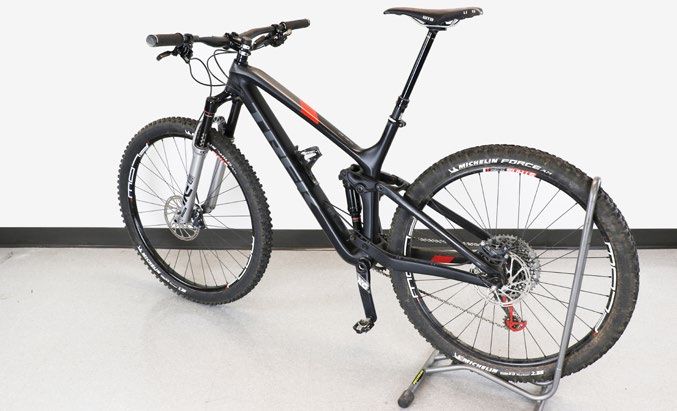
SAFETY FIRST!
We care about YOU. Please, always wear your safety glasses and
     protective gloves when servicing RockShox products.
            Protect yourself! Wear your safety gear!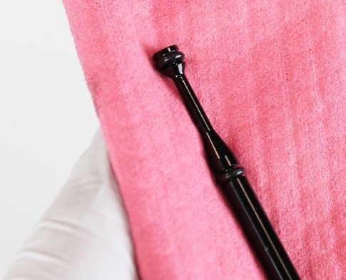
TABLE OF CONTENTS
       PRODUCT IDENTIFICATION - REVERB STEALTH C1.............................................................................................................................................................................6
       RECOMMENDED SERVICE INTERVALS..................................................................................................................................................................................................... 7
       SERVICE HISTORY............................................................................................................................................................................................................................................ 7
       BRASS KEY SIZE................................................................................................................................................................................................................................................ 7
       TORQUE VALUES..............................................................................................................................................................................................................................................8
       PARTS, TOOLS, AND SUPPLIES...................................................................................................................................................................................................................9

EXPLODED VIEW - REVERB STEALTH............................................................................................................................................................10

SEATPOST TROUBLESHOOTING......................................................................................................................................................................11
       VENT VALVE PROCEDURE........................................................................................................................................................................................................................... 11

SEATPOST SERVICE...........................................................................................................................................................................................14
       SEATPOST REMOVAL.................................................................................................................................................................................................................................... 14
       HYDRAULIC HOSE DISCONNECT............................................................................................................................................................................................................. 17

                                                                                                       50/200/600 Hour Service
       LOWER POST REMOVAL............................................................................................................................................................................................................................... 18

                                                                                                                 200 Hour Service
       TOP CAP AND SEAL HEAD BUSHING REPLACEMENT...................................................................................................................................................................... 21

                                                                                                                 600 Hour Service
       INNER SHAFT DISASSEMBLY.................................................................................................................................................................................................................... 25
       UPPER POST DISASSEMBLY...................................................................................................................................................................................................................... 29
       TOP CAP INSTALLATION.............................................................................................................................................................................................................................. 31
       INTERNAL FLOATING PISTON (IFP) INSTALLATION........................................................................................................................................................................... 32
       INNER SHAFT ASSEMBLY........................................................................................................................................................................................................................... 35
       POPPET VALVE INSTALLATION.................................................................................................................................................................................................................37
       INNER SHAFT INSTALLATION................................................................................................................................................................................................................... 39

                                                                                                       50/200/600 Hour Service
       LOWER POST INSTALLATION.................................................................................................................................................................................................................... 42
       BRASS KEY INSTALLATION........................................................................................................................................................................................................................ 43
       LOCK RING AND RETAINING RING INSTALLATION........................................................................................................................................................................... 45

REMOTE LEVER...................................................................................................................................................................................................47
       HOSE BARB REPLACEMENT (OPTIONAL)..............................................................................................................................................................................................47

HYDRAULIC HOSE............................................................................................................................................................................................. 50

                                                                                                       50/200/600 Hour Service
       CONNECT TO SEATPOST...........................................................................................................................................................................................................................50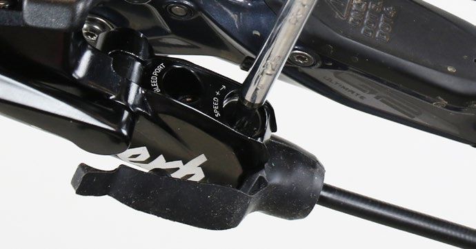
RockShox Service
We recommend that you have your RockShox suspension serviced by a qualified bicycle mechanic. Servicing RockShox suspension requires
knowledge of suspension components, as well as the use of specialized tools and lubricants/fluids. Failure to follow the procedures outlined in this
service manual may cause damage to your component and void the warranty.
Visit www.sram.com/service for the latest RockShox Spare Parts catalog and technical information. For order information, please contact your local
SRAM distributor or dealer.
Information contained in this publication is subject to change at any time without prior notice.
Your product's appearance may differ from the pictures contained in this publication.
      For recycling and environmental compliance information, please visit www.sram.com/company/environment.

 Part Preparation
Remove the component from the bicycle before service.
Clean the exterior of the product with mild soap and water to avoid contamination of internal sealing part surfaces.

 Service Procedures
The following procedures should be performed throughout service, unless otherwise specified.

To maintain proper lubrication and function, clean Reverb internal parts with
only a clean, lint-free shop towel. Clean the sealing surface on the part and
inspect it for scratches.

                                  NOTICE
 Reverb internal part and sealing surfaces must remain lubricated for proper
 function. Do not use liquid cleaners or isopropyl alcohol to remove oil or
 grease from internal parts or seals.

Clean Reverb external parts with soap and water, and a clean, lint-free shop
towel.
For hard to reach places (e.g. lower post tube), wrap a clean lint-free shop
towel around a non-metallic dowel to clean the inside.

Use your fingers to pinch and lift o-rings from the o-ring gland, then remove
the o-ring with a non-metallic pick as needed. Replace the o-ring or seal with
a new one from the service kit.

                                  NOTICE
 Do not scratch any sealing surfaces when servicing the product. Scratches
 can cause leaks. Consult the spare parts catalog to replace the damaged
 part.

Apply only RockShox Dynamic Seal Grease to the new seal or o-ring.

Use Reverb Vise Blocks when clamping Reverb parts in a bench vise.                                                     Specified torque value in N·m (in-lb)
Tighten the part with a torque wrench to the torque value listed in the red bar.
When using a crowfoot socket and torque wrench, install the crowfoot socket
at 90 degrees to the torque wrench.

                                                                                                                                  RockShox Service             5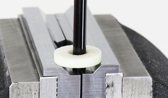
Product Identification - Reverb Stealth C1
Production versions of Reverb Stealth can be identified visually. Your Reverb                                             C1 - Collar
Stealth C1 can be identified by the saddle clamps, graphics, seatpost collar,
and poppet cover.

                                                                                C1 - Upper Post - Saddle Clamps

                                                                                                                          C1 - Poppet Valve Cover

                                                                                C1 - Graphics

                                                                                C1 - Poppet Valve Cover (Connectamajig)

                                                                                                    Product Identification - Reverb Stealth C1      6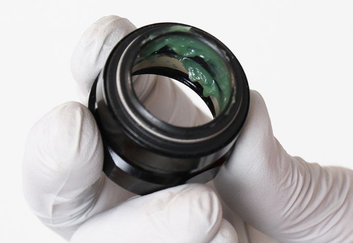
Recommended Service Intervals
Regular service is required to keep your RockShox product working at peak performance. Follow this maintenance schedule and install the service
parts included in each service kit that corresponds with the Service Hours Interval recommendation below. For spare part kit contents and details,
refer to the RockShox Spare Parts Catalog at www.sram.com/service.

 Service Hours Interval      Maintenance                                                   Benefit
                                                                                           Extends wiper seal lifespan
                             Clean dirt and debris from seatpost                           Minimizes damage to upper post
 Every ride                                                                                Minimizes lower post contamination
                             Inspect the upper post for scratches                          Minimizes lower post contamination
                             Check remote hydraulic pressure                               Ensures proper remote actuation function
                                                                                           Reduces friction
                             Remove the lower post, clean, inspect and replace brass
                             keys as needed, and apply new grease                          Extends wiper seal, top cap bushing, and brass key
 Every 50 Hours
                                                                                           lifespan
                             Perform remote lever bleed                                    Ensures proper remote actuation function

                             Replace all parts included in the Reverb Stealth C1 Service   Reduces friction
 Every 200 Hours             Kit - 200 hours                                               Extends seatpost lifespan
                             Perform full hydraulic remote system bleed                    Ensures proper remote actuation function
                             Replace all parts included in the Reverb Stealth C1 Service
                                                                                           Restores hydraulic system and function
 Every 600 Hours             Kit - 600 hours.
                             Perform full hydraulic remote system bleed                    Ensures proper remote actuation function

 Service History
Record each date of service to track service intervals.

                                                                              Service Hours Interval
                                50        100       150      200        250       300       350        400       450      500         550       600
 Date of Service

 Brass Key Size

 Size = Record the number of etched lines on each key. Replace with the same size keys.

                                                                                                               Recommended Service Intervals          7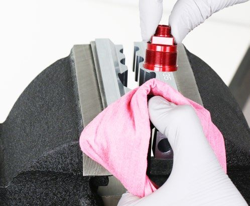
To r q u e Va l u e s

Part                                           Tool                                       Torque
Internal
Internal seal head to upper post               23 mm crowfoot                             28 N•m (248 in-lb)
Main piston to inner shaft                     9 mm crowfoot                              4 N•m (35 in-lb)
Poppet valve cover to poppet valve housing     15 mm crowfoot and 10 mm open end wrench   6.5 N•m (56 in-lb)
Lock ring to poppet valve cover                24 mm crowfoot and 15 mm open end wrench   5 N•m (60 in-lb)
External
Collar to lower post                           34 mm crowfoot                             28 N•m (250 in-lb)
Post barb strain relief nut to poppet cover    13 mm crowfoot and 15 mm open end wrench   8.5 N•m (75 in-lb)
Connectamajig coupler to poppet cover          8 mm crowfoot and 15 mm open end wrench    4 N•m (35 in-lb)
Connectamajig coupler collar to hose coupler   9 mm crowfoot and 6 mm open end wrench     2 N•m (18 in-lb)
Saddle clamp bolts                             T25 TORX bit socket                        6 N•m (53 in-lb)
Bicycle frame seatpost clamp                   Various                                    Do not exceed 6.7 N•m (59 in-lb)
Remote and Bleed
Reverb 1x remote barb strain relief nut        13 mm crowfoot                             8.5 N•m (75 in-lb)
Remote lever hose barb (standard)              6 mm crowfoot                              3.2 N•m (28 in-lb)
Remote lever clamp (MMX)                       T25 TORX bit socket                        5.5 N•m (49 in-lb)
Remote lever clamp (discrete)                  4 mm bit socket                            2 N•m (18 in-lb)
Remote bleed screw (standard)                  T10 TORX bit socket                        2 N•m (18 in-lb)
Post bleed screw                               T10 TORX bit socket                        2 N•m (18 in-lb)

                                                                                                                             8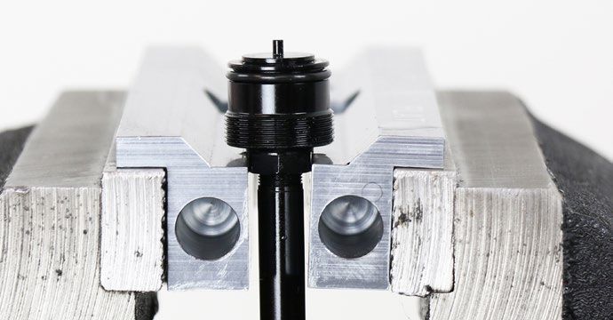
P a r t s , To o l s , a n d S u p p l i e s
Parts                                                                    Bicycle Tools
• Reverb Stealth C1 Service Kit - 200 hours                              • Bicycle work stand
• Reverb Stealth C1 Service Kit - 600 hours                              Tools
• Reverb brass keys, quantity 3 (use correct size)                       • Adjustable open end wrench (≤ 34 mm) (optional)
• Hose barbs (optional)                                                  • Bench vise
Safety and Protection Supplies                                           • Cone wrench: 24 mm
• Apron                                                                  • Crowfoot sockets: 6, 9, 10, 13, 15, 23, 24, 34 mm
• Clean, lint-free shop towel                                            • Dowel - non-metallic
• Nitrile gloves                                                         • Hex bit socket: 4 mm
• Oil pan                                                                • Hex wrenches: 1.5, 4 mm
• Safety glasses                                                         • Needle nose pliers
Lubricants and Fluids                                                    • Open end wrenches: 6, 9, 10, 13, 15, 23, 24, 34 mm
• Friction paste                                                         • Non-metallic pick
• Maxima Racing Oils Serene Hydraulic Seat Post Fluid                    • Plastic cable ties (quantity 7-10, 15-20 cm length)
• RockShox Dynamic Seal Grease                                           • Retaining ring pliers
RockShox Tools                                                           • Screwdriver with plastic handle
• Reverb IFP Height Tool - 210 mm                                        • Socket: 9 mm
• RockShox shock pump                                                    • Socket wrench
• RockShox Vent Valve Tool                                               • Torque wrench (see Torque Values chart for range)
• Reverb Vise Blocks                                                     • TORX bit sockets: T10, T25
                                                                         • TORX wrenches: T8, T10, T25

                                                        SAFETY INSTRUCTIONS
Always wear safety glasses and nitrile gloves when working with grease and seatpost hydraulic fluid.
Place an oil pan under the RockShox product during service.

                                                                 ⚠ WARNING
Do not allow seatpost hydraulic fluid to come into contact with disc brake levers, calipers, pads, rotors, or braking surfaces. If hydraulic fluid
contacts brake pads, the brake pads must be replaced. Use isopropyl alcohol to remove hydraulic fluid from any brake or braking surface. Failure
to remove hydraulic fluid from brakes and braking surfaces can damage components and reduce brake performance, and may result in serious
injury and/or death to the rider. Remove or cover brake components before performing seatpost service, hose replacement, or hydraulic remote
bleed procedures.

                                                                                                                     Parts, Tools, and Supplies      9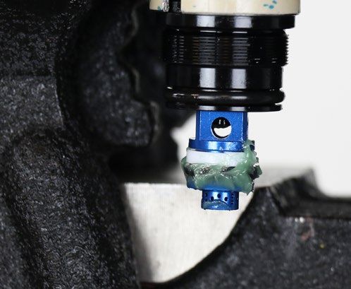
Exploded View - Reverb Stealth C1

       Inner Shaft
       Assembly

       Internal Floating Piston
       Assembly
                                                  Clamp Nut
       Poppet Valve                                         Saddle Clamp - Upper                                      STANDARD REMOTE
       Assembly
                                                                                                         Bleed Screw                               Actuator Piston
                                                                                            Speed Adjuster
                                                                Clamp Bolt                                                                                           Actuator
                                                                                   Remote Hose Barb

      Saddle Clamp - Lower

                                                                                                                                                          Clamp

                   Post Head

    Vent Valve / Air Valve Cap
                                                                                                                                        *REVERB 1X REMOTE
                                                                                                                           Actuator Piston                                Barb Strain Relief Nut

                                  Upper Post
                                                                                                                                                                            Hose Barb

                                                                                        Clamp Installation Mount
                                                                                                                                                           Speed Adjuster
                                                                                       Remote Lever                                                          Bleed Screw
                                                                                                                                                              Boot

                                                 IFP Tube

                                                                                                      Collar
                                        Internal Floating Piston (IFP)

                                                                                                               Brass Keys (x3)

                                                                                                                    Seal Head Bushing

                                                                         Main Piston

                                                                    Internal Seal Head
     CONNECTAMAJIG
                                                                                                                                 Lower Post

                                                                                          Inner Shaft

                                                        Connectamajig Coupler Assembly                                                              Poppet Valve Housing
                                                                                                                                                     Poppet Valve
                                                                                                                                                      Lock Ring
                                                            Connectamajig Collar                                                                       Poppet Valve Cover
                                                                                                                   Foam Ring
                                                                                                                                                           Barb Strain Relief Nut
                                                                                                                  Bleed Screw
                                                                                                                      Bleed Port

                                                                                                                          Hose Barb

*Compatible with Reverb Stealth and Reverb
                                                                                                                                              Exploded View - Reverb Stealth C1                    10
S e a t p o s t Tr o u b l e s h o o t i n g
The Vent Valve is located on the bottom of the seatpost and can be used after extended use if the seatpost develops a 'squish' suspension feel in
the fully extended position when the rider is seated. If this occurs after extended use, it is an indication that air and oil have mixed and the Vent Valve
should be used. Activating the Vent Valve will channel the air back into the air chamber and out of the oil.
NOTICE
The Vent Valve should be used only if the seatpost compresses more than 5 mm during normal use in the fully extended position while seated. Do
not use the Vent Valve if the seatpost is compressed. The Vent Valve is not to be used regularly and is only to be used if the seatpost compresses
abnormally while seated.
Vent Valve Procedure
Secure the bicycle in an upright position on a flat level surface.
1
Press the remote actuator until the seatpost is fully extended, then
2 release the actuator.
Remove the saddle from the seatpost.
3
Set the saddle clamps, bolts, and nuts aside.
T25
Seatpost Troubleshooting 11Depress the Vent Valve with the Vent Valve tool. Hold the top of the
4 seatpost head with your other hand. With the Vent Valve depressed,
push the lower post down, and slowly compress the seatpost.
Vent Valve Tool
When you feel a hard stop point, hold the seatpost in place for
2 seconds, then release the Vent Valve and stop pushing down on the
seatpost.
NOTICE
For proper Vent Valve function, the bicycle must be on a flat level
surface. The seatpost must be at a natural angle installed in the
bicycle, and not perpendicular to the ground.
To avoid hydraulic bypass, do not compress the seatpost beyond the
hard stop point. At the hard stop point, do not hold the Vent Valve
down for more than 2 seconds.
Press the remote actuator and release when the seatpost is fully
5 extended.
Test: Push down on the seatpost head to compress the seatpost. If the
6 Vent Valve procedure was successful, the seatpost will not compress.
If the seatpost still compresses, this may be an indication the seatpost
is in need of the 600 Hour service. Proceed to Seatpost Service.
Vent Valve Procedure 12If successful, install the saddle onto the seatpost.
7
Consult the Reverb, Reverb Stealth, 1x Remote User Manual at
www.sram.com/service for saddle installation procedures.
T25
T25
Vent Valve Procedure 13Seatpost Service
Seatpost Removal
Secure the bicycle in an upright position.
1
NOTICE
The Reverb Stealth seatpost will be removed from the bicycle.
Do not clamp the seatpost in a bicycle work stand.
Remove or cover the rear brake caliper to prevent contact with
2 hydraulic fluid.
Press the remote actuator until the seatpost is fully extended, then
3 release the actuator.
Reverb 1x Remote
Standard Remote
Seatpost Service 14Set the speed adjuster to the full slow position.
4 Reverb 1x Remote
Rotating the speed adjuster to the slowest setting is critical for a
successful bleed. Failure to do so may result in insufficient fluid
volume inside the hydraulic remote system.
Standard Remote: Turn the speed adjuster knob in the opposite
direction of the arrow (counter-clockwise) until it stops.
Reverb 1x Remote: Remove the remote boot and rotate it out of the
way. Turn the speed adjuster bolt (counter-clockwise) until it stops.
Standard Remote
T25 Reverb 1x Remote
Remove the remote lever assembly from the handlebar.
5 T25 Reverb 1x Remote
T25 Standard Remote
Remove the saddle from the seatpost.
6
Set the saddle clamps, bolts, and nuts aside.
T25
Seatpost Removal 15Loosen the seatpost clamp.
7
Remove the seatpost from the bicycle seat tube while simultaneously
8 pushing the hydraulic hose into the hose port in the bicycle frame.
Frame hose port
The hose port location will vary depending on the bicycle frame.
Consult with your frame manufacturer for additional information.
NOTICE
Do not pull the seatpost out of the frame if there is tension at the
hose. This can cause damage to the hydraulic hose and hose barb.
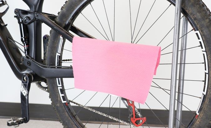
Clamp the seatpost into a bicycle work stand.
9
Place a shop towel under the seatpost and hose to absorb any
hydraulic fluid that may drip when the hose is disconnected.
Seatpost Removal 16Hydraulic Hose Disconnect
The hydraulic hose must be disconnected from the seatpost for all service procedures.
The hose does not need to be disconnected from the remote lever for seatpost service.
To avoid contact with hydraulic fluid, remove or cover the rear brake caliper before disconnecting the hydraulic hose.
⚠ WARNING
Do not allow seatpost hydraulic fluid to come into contact with any brake components. Contaminated brake components can compromise brake
performance, may cause brake failure, and can lead to serious injury and/or death.
Disconnect the hydraulic hose from the seatpost.
1 Hose barb and barb strain relief nut
Hose Barb with Barb Strain Relief Nut: Secure a plastic cable tie on
the hose. The cable tie will prevent the nut from dropping inside the
frame seat tube.
Unthread and remove the strain relief nut and hose assembly from the
poppet cover.
Wipe away any excess fluid from the hose barb.
15 mm 13 mm
Connectamajig: Unthread and remove the hose coupler (A) from the Connectamajig hose coupler
Connectamajig coupler collar (B). Service can be performed with the
Connectamajig coupler assembly (C) installed.
B
C
A
9 mm 6 mm
Hydraulic Hose Disconnect 1750/200/600 Hour Service Lower Post Removal
Before disassembly, confirm the seatpost is free of any dirt or contaminants.
Service procedures are the same for standard and Connectamajig seatpost hose connection types. The standard hose barb is pictured.
NOTICE
Use Reverb Vise Blocks to prevent damage to the seatpost or any seatpost component when clamping it into a vise. Clamp each component only
tight enough to prevent it from spinning in the vise blocks. To prevent the part from slipping, clean the vise blocks with a clean shop towel before
use.
Clamp the lower post into a bench vise with Reverb Vise Blocks.
1
Reverb Vise Blocks - 25-35 mm
Unthread the lock ring from the lower post.
2
24 mm or adjustable wrench
Push the upper post up.
3
Lower Post Removal 18Remove the lock ring from the poppet cover.
4
24 mm Cone wrench 15 mm
Unthread the seatpost collar.
5
Slide the collar down toward the post head.
34 mm or adjustable wrench
Remove the upper post assembly and set it aside on a clean shop
6 towel.
Remove the lower post from the vise.
Lower Post Removal 19Clean the inside and outside of the lower post, then set it aside.
7
Dowel
Clamp the upper post head into the vise with Reverb Vise Blocks.
8
Reverb Vise Blocks - FLAT
Remove the three brass keys from the upper post. Example: 3 lines = size 3 key
Record the number of lines, which indicate key size, marked on
the brass keys for future reference. If worn, the brass keys must be
replaced with new brass keys of the same size.
Clean the upper post and keys with a clean shop towel.
To continue with the 50 Hour Service proceed to Brass Keys Installation.
To continue with the 200 Hour Service proceed to Top Cap and Seal Head Bushing Replacement.
To continue with the 600 Hour Service proceed to Inner Shaft Disassembly.
Lower Post Removal 20200 Hour Service To p C a p a n d S e a l H e a d B u s h i n g R e p l a c e m e n t
The following steps are to be completed during the 200 hour service interval and include replacing parts included in the Reverb Stealth C1 Service
Kit - 200 hours. These steps do not require complete disassembly of the upper post assembly and are not included in the 600 hour service.
Depressurization of the seatpost is not required prior to beginning the 200 hour service procedure.
Remove the foam ring from the inner shaft assembly and discard the
1 foam ring.
Wrap a clean shop towel around the inner shaft at the seal head. The
2 towel will protect the inner shaft.
Spread the seal head bushing and remove it from the seal head.
Remove the bushing and discard it.
Remove the towel.
NOTICE
The seal head bushing may have sharp edges. Do not scratch the
inner shaft with the bushing. Scratches will cause leaks.
Retaining ring pliers
Remove the seal head o-ring. Pinch the o-ring, lift it from the o-ring
3 groove, and remove it. Discard the o-ring.
Non-metallic pick
Top Cap and Seal Head Bushing Replacement 21Remove the collar from the upper post and discard it.
4
Clean the upper post and inner shaft assembly with a clean shop towel.
Apply a liberal amount of RockShox Dynamic Seal Grease around the
5 inside of a new collar and onto the seals.
Carefully, install the new top cap assembly, dust wiper seal end first,
onto the upper post assembly over the seal head. Slide the collar down
until it is positioned below the upper post key slots.
NOTICE
Ensure the dust wiper seal slides over the seal head without folding
the outer lip of the seal.
Use care when installing the collar to avoid damage to the wiper seal
or bushing which can be caused by forceful contact with the seal
head edges.
Top Cap and Seal Head Bushing Replacement 22Install a new o-ring onto the seal head.
6
Wrap a clean shop towel around the inner shaft at the poppet housing.
7
Carefully spread the bushing ends enough to fit over the poppet
housing.
Position the new bushing over the poppet housing and around the
towel. Slide the towel and bushing down to the seal head. The towel
will protect the inner shaft.
Remove the towel.
NOTICE
The seal head bushing may have sharp edges. Do not scratch the
inner shaft with the bushing. Scratches may cause leaks.
Pinch the bushing to secure it around the seal head and o-ring.
Top Cap and Seal Head Bushing Replacement 23Install a new foam ring.
8
NOTICE
Do not damage the foam ring during installation.
To continue with the 200 Hour Service proceed to Brass Key Installation.
Top Cap and Seal Head Bushing Replacement 24600 Hour Service Inner Shaft Disassembly
⚠ WARNING - EYE HAZARD
The seatpost must be depressurized before disassembly. During disassembly, there may be remaining air pressure inside the upper post assembly.
Keep your eyes and face away from the poppet valve housing during disassembly. Wear safety glasses.
Remove the air cap.
1 9 mm
Depress the Schrader valve and release all air pressure from the air
2 chamber.
⚠ WARNING - EYE HAZARD
Verify all pressure is removed from the seatpost before proceeding.
Failure to do so can cause the inner seal head and inner shaft to
separate from the upper post assembly at high velocity during
disassembly. Wear safety glasses.
Hex wrench or pick
Clamp the poppet housing wrench flats in the Reverb Vise Blocks.
3 15 mm
Unthread the poppet valve cover from the poppet valve housing two
full turns. Do not remove the poppet cover.
NOTICE
To avoid damage to the inner shaft, do not clamp the inner shaft into
the flat section of the Reverb Vise Blocks.
Reverb Vise Blocks - FLAT
Wrap a shop towel over the poppet valve cover. Unthread the poppet
4 valve cover slowly by hand. Remove the poppet valve cover from the
poppet valve housing slowly and cover the poppet valve housing
opening with your thumb to prevent the poppet valve from dislodging
or ejecting from the inner shaft.
⚠ WARNING - EYE HAZARD
In the event there is any remaining air pressure inside the upper
post assembly, covering the poppet valve housing with your thumb
will prevent the poppet from disloding during removal. Covering the
housing with a shop towel will absorb hydraulic fluid if discharged
during removal.
Inner Shaft Disassembly 25With a shop towel around the poppet valve housing, and your thumb
5 still on the poppet valve, use needle nose pliers to remove the poppet
valve from the housing and inner shaft.
⚠ WARNING - EYE HAZARD
In the event there is any remaining air pressure inside the upper post
assembly, covering the poppet valve housing with a shop towel will
absorb hydraulic fluid if discharged during removal.
NOTICE
Do not bend the poppet valve during removal. If the poppet valve is
damaged it cannot be used.
Needle nose pliers
Remove the upper post assembly from the vise.
6
Clamp the seapost head into the vise with Reverb Vise Blocks.
Reverb Vise Blocks - FLAT
Unthread the internal seal head three full turns. Do not remove the seal
7 head.
23 mm or adjustable wrench
Inner Shaft Disassembly 26Wrap a shop towel around and over the internal seal head.
8
Slowly unthread the seal head by hand while holding the shop towel
over the seal head.
A small amount of air pressure may be released when the seal head is
completely unthreaded. Do not remove the shop towel from the seal
head until the seal head is completely unthreaded.
Wrap the shop towel around the upper post to absorb hydraulic fluid
and carefully remove the seal head and inner shaft assembly from the
upper post.
Set the assembly aside on a clean shop towel.
⚠ WARNING - EYE HAZARD
In the event there is any remaining air pressure inside the upper post
assembly, the shop towel will absorb any fluid that may be released
under pressure. Do not remove the shop towel until the seal head is
completely removed from the upper post.
Remove the upper post from the vise and pour the hydraulic fluid into
9 an oil pan or container.
Set the upper post aside on a clean shop towel.
Inner Shaft Disassembly 27Wipe the inner shaft and Reverb Vise Blocks with a clean shop towel.
10 The clamping surfaces must be clean.
9 mm
Clamp the inner shaft into the Reverb Vise Blocks with the main piston
up.
Remove the main piston from the inner shaft.
Reverb Vise Blocks - 7.5 mm
Remove the internal seal head assembly from the inner shaft and
11 discard the seal head.
Remove the foam ring and discard it.
Remove the inner shaft from the vise and set it aside on a clean shop
12 towel.
Inner Shaft Disassembly 28600 Hour Service Upper Post Disassembly
Clamp the seapost head into the vise with Reverb Vise Blocks.
1
Remove the collar from the upper post and discard it.
Reverb Vise Blocks - FLAT
Insert a non-metallic pick into one of the cross holes in the IFP tube.
2 Carefully pull the IFP tube out of the upper post and remove it from
the post. Use your hand to guide the IFP tube straight out of the upper
post using care not to scratch the inside of the upper post with the hex
wrench.
Wipe the outer surface of the IFP tube and set it aside on a clean shop
towel.
NOTICE
Do not scratch the inner surface of the upper post or the outer
surface of the IFP tube. Surface scratches can cause leaks and reduce
performance.
If the IFP tube is scratched, it must be replaced. Non-metallic pick
Upper Post Disassembly 29Remove the internal floating piston (IFP) from the upper post. Insert
3 seven to nine plastic cable ties (cable tie size may vary), one at a time,
into the upper post and through the center of the IFP.
Pull the cable ties out of the upper post and remove the IFP.
Optional: Use the hooked end of the non-metallic pick to remove the
IFP.
Discard the IFP.
Plastic cable ties
C1 IFP
Upper Post Disassembly 30600 Hour Service To p C a p I n s t a l l a t i o n
Apply a liberal amount of RockShox Dynamic Seal Grease around the
1 inside of a new collar and onto the seals.
Wipe the outside of the upper post with a clean shop towel.
2
Install the new collar, dust wiper seal end first, onto the upper post.
Slide the collar down until it is positioned below the brass key slots.
NOTICE
Ensure the dust wiper seal slides over the upper post without folding
the outer lip of the seal.
Top Cap Installation 31600 Hour Service Internal Floating Piston (IFP) Installation
Pull the Vent Valve out to full extension to close the valve. Thread a
1 shock pump onto the air valve and pull the valve out until it stops.
Remove the shock pump.
NOTICE
To ensure proper function, the Vent Valve must be closed before IFP
installation.
Shock pump
Fully coat the inside and outside surfaces of the IFP tube with seatpost
2 hydraulic fluid.
Install the IFP tube with the cross holes facing up, into the upper post.
Use your finger to rotate the IFP tube in a circular and side to side
motion until the IFP tube seats itself onto the seal inside the bottom of
the upper post.
Push down firmly on the IFP tube until it snaps securely into the upper
post. When the IFP tube snaps into place, a click will be heard. Ensure
the IFP tube is secured and centered.
NOTICE
Do not scratch the inside of the upper post with the IFP tube. Do not
scratch the outside of the IFP tube on the edge of the upper post.
Scratches can cause leaks.
The IFP tube should be below the top of the upper post when it is
installed correctly.
Internal Floating Piston (IFP) Installation 32Apply a very liberal amount of RockShox Dynamic Seal Grease to the
3 outer and inner surfaces of the new gray C1 IFP, then submerge the IFP
in seatpost hydraulic fluid.
NOTICE
Install only the new gray C1 IFP.
The outer and inner surfaces must be coated with grease and
seatpost hydraulic fluid to prevent stiction. Stiction will negatively
affect seatpost function.
RockShox Dynamic Seal Grease
Seatpost hydraulic fluid
Install the greased IFP into the upper post and onto the IFP tube.
4 Gently and evenly push the IFP down until it is level with the top of the
IFP tube.
The IFP is symmetrical. Orientation of the IFP is not critical to
installation.
Internal Floating Piston (IFP) Installation 33Internal floating piston (IFP) height:
5
Identify the IFP height (H) measurement on the IFP tool.
Reverb Stealth C1 Seatpost Length IFP Height (H)
Travel (mm) (mm) (mm)
100 296 (H)
125 346
150 409 55
175 462
200 514.5
Reverb IFP Height Tool
IFP height is critical to proper function.
Set the internal floating piston (IFP) height inside the upper post.
6 Plastic screwdriver handle
Position the Reverb IFP height tool flat on the IFP. Gently tap the top of
the tool with a plastic screwdriver handle to push the IFP down into the
upper post.
Reverb IFP Height Tool
Stop when the correct measurement on the IFP tool is level with the
top of the upper post.
Remove the IFP tool from the upper post.
Remove the upper post assembly from the vise and set it aside on a
clean shop towel.
Internal Floating Piston (IFP) Installation 34600 Hour Service Inner Shaft Assembly
NOTICE
Inspect each part for scratches. Do not scratch any sealing surfaces when
servicing your suspension. Scratches can cause leaks.
When replacing o-rings, use your fingers or a non-metallic pick to remove
the o-ring. Clean each part with a clean lint-free shop towel.
Apply RockShox Dynamic Seal Grease to Reverb seals and o-rings.
Clean the inner shaft and Reverb Vise Blocks with a clean shop towel.
1 The clamping surfaces must be clean.
Clamp the inner shaft into the Reverb Vise Blocks, poppet housing
down.
Reverb Vise Blocks - 7.5 mm
Install a new foam ring onto the inner shaft.
2
Apply a liberal amount of RockShox Dynamic Seal Grease to the inside
3 of a new internal seal head assembly.
A
Install the internal seal head assembly onto the inner shaft, hex end (A)
first.
Slide the internal seal head below the shaft end.
NOTICE
If the seal head is installed onto the shaft in either the correct
orientation and removed, or the incorrect orientation and removed,
the internal oil seal will become permanently damaged from the shaft
threads and it cannot be used. If the new seal head is installed and
removed, the seal head must be discarded and a new seal head must
be installed in the correct orientation.
Inner Shaft Assembly 35Thread the main piston onto the inner shaft by hand.
4 10 mm 4 N•m (35 in-lb)
Tighten the main piston to the specified torque.
NOTICE
Do not scratch the inner shaft with the wrench as this is a critical
sealing surface. Surface scratches can cause leaks and reduce
performance.
Remove the inner shaft assembly from the vise.
5
Remove the main piston o-ring, and discard it.
Apply RockShox Dynamic Seal Grease to the new main piston o-ring
and install it.
NOTICE
Do not scratch any part of the main piston seal gland.
Non-metallic pick
Slide the seal head assembly toward the main piston until it stops.
6
Set the inner shaft assembly aside on a clean shop towel.
Inner Shaft Assembly 36600 Hour Service Poppet Valve Installation
Clamp the inner shaft into the Reverb Vise Blocks, poppet valve
1 housing oriented up.
Reverb Vise Blocks - 7.5 mm
Clean the poppet valve and o-rings with a clean lint-free shop towel.
2
Remove and discard only the o-ring at the narrow end (A) of the poppet
valve. Clean the o-ring gland with a clean lint-free shop towel. Install a
new o-ring.
A
Non-metallic pick
Poppet Valve Installation 37Coat each o-ring with seatpost hydraulic fluid.
3
Seatpost hydraulic fluid
Wipe fluid from the poppet valve under the large o-ring.
NOTICE
Allow excess fluid to drip off poppet valve before installation.
Excessive fluid coating may decrease performance.
Insert the poppet valve into the inner shaft, narrow end first.
4
Push the poppet valve into the poppet valve housing until the large
o-ring is 4 mm above the top edge of the poppet valve housing.
The o-ring at the narrow end of the poppet valve should not be visible
through the valve hole in the main piston.
NOTICE 4 mm
Do not bend the poppet valve during installation. If the poppet valve
is damaged it cannot be used.
Remove the inner shaft assembly from the vise and set it aside on a
clean shop towel.
Poppet Valve Installation 38600 Hour Service Inner Shaft Installation
Clamp the upper post head back into the Reverb Vise Blocks.
1 Seatpost hydraulic fluid
Wrap a shop towel around the top of the upper post. Pour seatpost
hydraulic fluid into the IFP tube until the fluid overflows into the upper
post and is level with the top of the upper post.
Reverb Vise Blocks - FLAT
Use your finger to remove any bubbles from the surface of the fluid if
bubbles are visible.
Hold the inner shaft and press the seal head against the main piston
2 with your thumb. Insert the main piston into the fluid and IFP tube.
Inner Shaft Installation 39Push the seal head into the upper post and thread the seal head into
3 the upper post by hand.
The poppet valve may move slightly up in the poppet valve housing
during seal head installation. If this occurs, carefully push the poppet
valve back into the poppet valve housing, without moving the inner
shaft, and stop when the large o-ring is 4 mm above the top edge of
the poppet housing. 4 mm
NOTICE
Do not compress the inner shaft into the upper post and IFP tube
until the seatpost is completely assembled and pressurized. If the
inner shaft does get pressed into the IFP tube, the IFP removal and
installation procedures must be repeated.
Tighten the seal head to the specified torque.
4
23 mm 28 N•m (250 in-lb)
Push the poppet valve into the poppet housing until the large o-ring
5 engages the housing and the top of the poppet valve is flush with the
top of the housing.
The poppet valve may extend from the housing due to internal
hydraulic pressure. If this occurs, gently push it back into the housing.
NOTICE
Do not scratch the inner shaft with the wrench as this is a critical
sealing surface. Surface scratches can cause leaks and reduce
performance.
Do not compress the inner shaft into the upper post and IFP tube
until the seatpost is completely assembled and pressurized. If the
inner shaft does get pressed into the IFP tube, the IFP removal and
installation procedures must be repeated.
Inner Shaft Installation 40Remove the upper post assembly from the vise.
6
Clamp the poppet housing wrench flats in the Reverb Vise Blocks.
NOTICE
To avoid damage to the inner shaft, do not clamp the inner shaft into
the flat section of the Reverb Vise Blocks.
Reverb Vise Blocks - FLAT
Install the poppet valve cover onto the poppet valve housing and
7 thread it on by hand.
15 mm 6.5 N•m (in-lb)
Tighten the poppet valve cover onto the poppet valve housing to the
specified torque.
Remove the upper post assembly from the vise.
Inner Shaft Installation 4150/200/600 Hour Service Lower Post Installation
Clamp the upper post head into the vise with Reverb Vise Blocks.
1
Reverb Vise Blocks - FLAT
Apply a liberal amount of RockShox Dynamic Seal Grease onto the seal
2 head bushing.
Apply a liberal amount of RockShox Dynamic Seal Grease to the inside
3 of the lower post tube and into the key grooves.
Install the lower post onto the upper post.
4
Squeeze the seal head bushing, and slide the lower post down over
the seal head bushing. Stop when the lower post covers the bushing.
Lower Post Installation 4250/200/600 Hour Service Brass Key Installation
NOTICE New Brass Key
Side-to-side movement of the upper tube is an indication that the brass keys
are worn and need to be replaced. Vertical lines on the key are an indication
that the key is worn.
New brass keys must be the same size and have the same number of
etched lines as the original brass keys for proper function.
Refer to the RockShox spare parts catalog at
www.sram.com/service for a list of brass key kits available.
Worn Brass Key
Apply a liberal amount of RockShox Dynamic Seal Grease onto each
1 key slot.
Install the brass keys into the key slots. The orientation of the brass
keys is not critical.
Apply a liberal amount of RockShox Dynamic Seal Grease onto the
brass keys and upper post.
Slide the collar up and down to lubricate the upper post and the collar
bushing and seal.
Brass Key Installation 43Align the lower post key slots with the brass keys and ensure the laser
2 etched RockShox logo is aligned with the back of the seatpost head.
Key Slots
Hold each brass key in place and slide the lower post down until it
engages the keys. Continue to slide the lower post down over the
brass keys.
Slide the collar up until it contacts the lower post threads. Thread the
collar onto the lower post by hand.
Tighten the collar.
3
Remove the seatpost from the vise.
NOTICE
Do not scratch the upper post with the wrench. Scratches can allow
contaminants to enter the lower tube, damage the upper post outer
surface, and degrade performance.
34 mm 28 N•m (250 in-lb)
Brass Key Installation 4450/200/600 Hour Service Lock Ring and Retaining Ring Installation
Clamp the lower post into the Reverb Vise Blocks with the post head
1 oriented up.
300 psi (20.7 bar)
Pressurize the seatpost to 300 psi (20.7 bar).
Reverb Vise Blocks - 25-35 mm
Reinstall the air cap finger tight. 9 mm
Remove the seatpost from the vise and clamp the lower post into the
2 Reverb Vise Blocks with the post head oriented down.
Push the upper post up to expose the poppet valve housing.
Reverb Vise Blocks - 25-35 mm
Install the lock ring onto the poppet valve cover and thread it on by
3 hand.
24 mm 5 N•m (60 in-lb) 15 mm
Tighten the lock ring onto the poppet valve cover to the specified
torque.
NOTICE
Do not scratch the inner shaft with the wrench as this is a critical
sealing surface. Surface scratches can cause leaks and reduce
performance.
Lock Ring and Retaining Ring Installation 45Pull the upper post down to full extension until the lock ring threads
4 contact the lower post.
24 mm 5 N•m (60 in-lb) 15 mm
Thread the lock ring into the lower post and tighten it to the specified
torque.
Remove the seatpost from the vise.
To continue with the 50/200/600 Hour Service proceed to Connect to Seatpost.
Lock Ring and Retaining Ring Installation 46Remote Lever
Hose Barb Replacement (OPTIONAL)
Replace the remote hose barb only if it is damaged from impact.
If the hydraulic hose assembly is removed from the bicycle, refer to the 'Reverb Stealth and Reverb Hydraulic Hose Replacement and Remote System
Bleed' manual at www.sram.com/service for installation procedures. For a list of available Reverb Stealth hydraulic hose kits, refer to the RockShox
Spare Parts catalog at www.sram.com/service.
NOTICE
If Reverb hydraulic fluid leaks from the remote lever while under pressure or in use, the remote lever assembly must be replaced.
Hold the hydraulic hose near the hose barb. Rotate the Reverb remote
1 lever counterclockwise and unthread the hose from the remote
hose barb.
Standard Remote
Reverb 1x Remote
2a Standard Remote: Unthread the barb from the remote and discard it.
6 mm Standard Remote
Install a new hose barb and tighten it.
6 mm 3.2 N•m (28 in-lb)
Remote Lever 472b Reverb 1x Remote: Remove the strain relief nut.
13 mm Reverb 1x Remote
Remove the hose barb and discard it.
Cut 3 - 4 mm off the end of the hose.
3
Hydraulic hose cutters
4a Standard Remote: Thread the remote lever hose barb into the
hydraulic hose. Hold the end of the hose and rotate the remote lever
clockwise while pushing the remote lever barb into the hose. Stop
when the hose is hand tight on the hose barb.
NOTICE
Do not over-tighten and strip the threads inside the hydraulic hose. If
the hose is over or under tightened, hydraulic fluid can leak.
Hose Barb Replacement (OPTIONAL) 48Reverb 1x Remote: Insert the strain relief nut onto the hose.
4b
Thread a new hose barb into the hose until it contacts the barb flange.
NOTICE
Do not over-tighten and strip the threads inside the hydraulic hose. If
the hose is over or under tightened, hydraulic fluid can leak.
T8
Reverb 1x Remote: Insert the hose barb into the remote and thread the
4c strain relief nut onto the remote.
Tighten to the correct torque.
13 mm 8.5 N•m (75 in-lb)
The Reverb remote hydraulic system must be bled after the hose is installed onto the remote lever. Refer to the 'Reverb Stealth and Reverb
Hydraulic Hose Replacement and Remote System Bleed' manual, available at www.sram.com/service, for hydraulic remote system bleed and
seatpost installation procedures.
Hose Barb Replacement (OPTIONAL) 49Hydraulic Hose
50/200/600 Hour Service Connect to Seatpost
There are two Reverb Stealth C1 hydraulic hose connection types: 1) hose barb and barb strain relief nut and 2) Connectamajig. Follow the procedure
in step 2 for the hose connection type on your Reverb Stealth C1.
Clamp the seatpost into a bicycle work stand. Position the bicycle
1 under the seatpost. Place a shop towel under the seatpost and hose to
absorb any hydraulic fluid that may drip.
Push the hydraulic hose into the frame hose port as needed.
⚠ WARNING
Do not allow Reverb hydraulic fluid to come into contact with
any brake components. Contaminated brake components can
compromise brake performance, may cause brake failure, and can
lead to serious injury and/or death.
2a Hose Barb and Barb Strain Relief Nut: Place the flat end of the hose
barb into the recessed end of the poppet valve cover. Thread the strain
relief nut onto the poppet valve cover and tighten it to the specified
torque.
Remove the cable tie.
15 mm 8.5 N•m (75 in-lb) 13 mm
Hydraulic Hose 50Connectamajig: Connect the hose coupler (A) to the Connectamajig
2b coupler collar (B). Use your fingers to push the Connectamajig hose
coupler firmly into the Connectamajig coupler collar until it stops; hold
it in place.
B
A
Thread the hose coupler into the Connectamajig coupler by turning the 9 mm 2 N•m (18 in-lb) 6 mm
coupler collar clockwise.
Use a 6 mm open end wrench to hold the hose coupler and tighten the
Connectamajig coupler collar to the specified torque.
This concludes service for the RockShox Reverb Stealth C1 adjustable height seatpost.
The Reverb Stealth hydraulic remote system must be bled before the seatpost can be reinstalled and used. Refer to the Reverb Stealth and
Reverb Hydraulic Hose Replacement and Remote System Bleed manual, available at www.sram.com/service, for bleed and seatpost installation
procedures.
Connect to Seatpost 51These are registered trademarks of SRAM, LLC: 1:1®, Accuwatt®, Avid®, Bar®, Blackbox®, BoXXer®, DoubleTap®, Elita®, eTap®, Firecrest®, Firex®, Grip Shift®, GXP®, Hammerschmidt®, Holzfeller®, Hussefelt®, i-Motion®, Judy®, Know Your Powers®, NSW®, Omnium®, Pike®, PowerLock®, Quarq®, Qollector®, RacerMate®, Reba®, Rock Shox®, Ruktion®, Service Course®, ShockWiz®, SID®, Single Digit®, Speed Dial®, Speed Weaponry®, Spinscan®, SRAM®, SRAM APEX®, SRAM EAGLE®, SRAM FORCE®, SRAM RED®, SRAM RIVAL®, SRAM VIA®, Stylo®, Torpedo®, The Power of Bicycles®, Truvativ®, Varicrank®, Velotron®, World Bicycle Relief®, X0®, X01®, X-SYNC®, XX1®, Zed tech®, Zipp® These are registered logos of SRAM, LLC: These are trademarks of SRAM, LLC: 10K™, 1X™, 202™, 30™, 35™, 302™, 303™, 404™, 454™, 808™, 858™, 3ZERO MOTO™, ABLC™, AeroGlide™, AeroBalance™, AeroLink™, Airea™, Air Guides™, AKA™, AL-7050-TV™, Automatic Drive™, Automatix™, AxCad™, Axial Clutch™, AXS™, BB5™, BB7™, BB30™, Bleeding Edge™, Blipbox™, BlipClamp™, BlipGrip™, Blips™, Bluto™, Bottomless Tokens™, Cage Lock™, Carbon Bridge™, Centera™, Charger 2™, Charger™, Clickbox Technology™, Clics™, Code™, Cognition™, Connectamajig™, Counter Measure™, DD3™, DD3 Pulse™, DebonAir™, Deluxe™, Deluxe Re:Aktiv™, Descendant™, DFour™, DFour91™, Dig Valve™, DirectLink™, Direct Route™, DOT 5.1™, Double Decker™, Double Time™, Dual Flow Adjust™, Dual Position Air™, DUB™, DZero™, E300™, E400™, Eagle™, E-Connect4™, E-matic™, ErgoBlade™, ErgoDynamics™, ESP™, EX1™, Exact Actuation™, Exogram™, Flow Link™, FR-5™, Full Pin™, Gnar Dog™, Guide™, GX™, Hard Chrome™, Hexfin™, HollowPin™, Howitzer™, HRD™, Hybrid Drive™, Hyperfoil™, i-3™, Impress™, Jaws™, Jet™, Kage™, Komfy™, Level™, Lyrik™, MatchMaker™, Maxle™, Maxle 360™, Maxle DH™, Maxle Lite™, Maxle Lite DH™, Maxle Stealth™, Maxle Ultimate™, Micro Gear System™, Mini Block™, Mini Cluster™, Monarch™, Monarch Plus™, Motion Control™, Motion Control DNA™, MRX™, Noir™, NX™, OCT™, OmniCal™, OneLoc™, Paragon™, PC-1031™, PC-1110™, PC-1170™, PG-1130™, PG-1050™, PG-1170™, Piggyback™, Poploc™, Power Balance™, Power Bulge™, PowerChain™, PowerDomeX™, Powered by SRAM™, PowerGlide™, PowerLink™, Power Pack™, Power Spline™, Predictive Steering™, Pressfit™, Pressfit 30™, Prime™, Qalvin™, R2C™, RAIL™, Rapid Recovery™, Re:Aktiv ThruShaft™, Recon™, Reverb™, Revelation™, Riken™, Rise™, ROAM™, Roller Bearing Clutch™, RS-1™, Sag Gradients™, Sawtooth™, SCT - Smart Coasterbrake Technology, Seeker™, Sektor™, SHIFT™, ShiftGuide™, Shorty™, Showstopper™, Side Swap™, Signal Gear Technology™, SL™, SL- 70™, SL-70 Aero™, SL-70 Ergo™, SL-80™, Sl-88™, SLC2™, SL SPEED™, SL Sprint™, Smart Connect™, Solo Air™, Solo Spoke™, SpeedBall™, Speed Metal™, SRAM APEX 1™, SRAM Force 1™, SRAM RIVAL 1™, S-series™, Stealth-a-majig™, StealthRing™, Super-9™, Supercork™, Super Deluxe™, Super Deluxe Coil™, SwingLink™, TaperCore™, Timing Port Closure™, Tool-free Reach Adjust™, Top Loading Pads™, Torque Caps™, TRX™, Turnkey™, TwistLoc™, Tyrewiz™, VCLC™, Vivid™, Vivid Air™, Vuka Aero™, Vuka Alumina™, VukaBull™, Vuka Clip™, Vuka Fit™, Wide Angle™, WiFLi™, X1™, X5™, X7™, X9™, X-Actuation™, XC™, X-Dome™, XD™, XD Driver Body™, XDR™, XG-1150™, XG-1175™, XG-1180™, XG-1190™, X-Glide™, X-GlideR™, X-Horizon™, XLoc Sprint™, XX™, Yari™, Zero Loss™ Specifications and colors subject to change without prior notice. © 2019 SRAM, LLC This publication includes trademarks and registered trademarks of the following companies: Maxima™ and Serene™ are trademarks of Maxima Racing Oils. TORX® is a registered trademark of Acument Intellectual Properties, LLC.
You can also read