2021 TOFINO - OWNER'S MANUAL - Ram ProMaster 1500 - Pleasure-Way
←
→
Page content transcription
If your browser does not render page correctly, please read the page content below
2021 TOFINO
   Ram ProMaster 1500

OWNER’S MANUAL

                        1
WARNING
    IT IS NOT SAFE TO USE COOKING APPLIANCES FOR COMFORT HEATING.
    Cooking appliances need fresh air for safe operation.

    Before Operation:
    Open overhead vent or turn on exhaust fan.
    Open Window.

    FAILURE TO COMPLY COULD RESULT IN DEATH OR SERIOUS INJURY.
    Unlike homes, the amount of oxygen supply is limited due to the size of the recreational vehicle, and proper ventilation
    when using the cooking appliances(s) avoids dangers of asphyxiation. It is especially important that cooking appliances
    not be used for comfort heating, as the danger of asphyxiation is greater when the appliance is used for long periods of
    time.

         WARNING
    DO NOT FILL CONTAINER (S) TO MORE THAN 80 PERCENT OF CAPACITY. FAILURE TO
    COMPLY COULD RESULT IN DEATH OR SERIOUS INJURY.
    Overfilling the propane container can result in uncontrolled propane flow, which can cause fire or explosion. A properly
    filled container contains approximately 80 percent of its volume as liquid propane.

         DANGER
    IF YOU SMELL PROPANE:
    Extinguish any open flames, pilot lights and smoking materials.
    Do not touch electrical switches.
    Shut off the propane supply at the container valve(s) or propane supply connection.
    Open doors and other ventilating openings.
    Leave the area until the odor clears.
    Have the propane system checked and leakage source corrected before using again.
    Failure to comply could result in explosion resulting in death or serious injury.

          WARNING
    Propane cylinders shall not be placed or stored inside the vehicle. Propane cylinders are equipped with safety devices
    that relieve excessive pressure by discharging propane to the atmosphere.

    FAILURE TO COMPLY COULD RESULT IN DEATH OR SERIOUS INJURY.

2
Pleasure-Way Industries Ltd. takes great pride in the quality
and excellence that the Pleasure-Way name represents. We
appreciate having you as a customer and welcome you into the
Pleasure-Way family. This manual is provided to introduce you
to the many features of your new Tofino including operation,
maintenance and warranties. We strongly advise you to take
time to read this manual, the Ram ProMaster chassis owners
manual as well as those of the motorhome components
before you use your new motorhome. It will help you to better
understand the many operational features of this recreational
vehicle.

After reading this manual, be sure to keep it in the motorhome
as a reference. Your Pleasure-Way dealer will be glad to answer
any further questions about the operation of your motorhome
and the appliances.

All reasonable precautions have been taken in the preparation of
this manual. We have been as accurate as possible at the time
of this publication. However, due to our policy of continuous
improvement and refinement to our product, Pleasure-Way
reserves the right to make product changes at any time without
prior notice and without incurring obligations. As a result,
Pleasure-Way assumes no responsibility for errors or omissions
in the accuracy in the content of this manual.
                                                                   Tofino
We know that you will enjoy your new Pleasure-Way and we wish
you many miles of pleasant and carefree driving. Happy Travels!

                                                                            3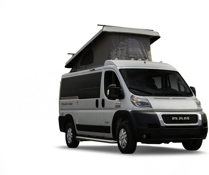
TABLE OF
           CONTENTS
    01   WARRANTY/POLICIES                               14   MAINTAINING YOUR MOTORHOME
    06   SAFETY                                          15   TRAVEL PREPARATION
    06   Occupant And Cargo Carrying Capacity            16   MOTORHOME SYSTEMS
    06   Smoke Detector                                  16   LP Gas System
    07   Fire Extinguisher                               17   LP Tank Gauge
    07   LP/Carbon Monoxide Detector                     17   LP Fill and Bleeder Valve
    07   GFCI Outlet                                     17   BBQ Quick Connect
    08   Refueling                                       18   How To Use The LP Appliances
    08   Filling the LP Gas Fuel Cylinder                18   Furnace
    08   Appliances                                      18   Cooktop
    09   Road Safety Strap                               19   Fresh Water System
    09   Seat Belts                                      19   Fresh Water Fill and Drain
    09   Vehicle Ground Clearance                        19   Fresh Water System Drains
    09   Emergency Escape                                19   Low Point Drain Valve
    10   MOTORHOME EXTERIOR                              20   Water Pump & Trouble Shooting
    10   Chassis Paint Code                              20   City Water Connection
    10   Dimensions/Capacities/Specs/Appliances          21   Kitchen Faucet
    12   Tire and Loading Information                    21   Spray Port
    12   Propane Fill, Breather Valve & BBQ Quick Con-   21   Waste System
         nect
                                                         21   Sewer Hose and Gate Valve Drain
    12   Sewer Dump Compartment
                                                         22   WINTERIZING
    12   Utility Center
                                                         22   Winterizing The Water System
    12   Fresh Water Holding Tank
                                                         22   Optional Winterizing for Milder Climates
    13   Furnace Vent
                                                         23   Winter Storage Electrical
    13   Exterior 110 Volt Plug
    13   Porch Light
    13   Solar Panel Package
    13   Roof Rack

4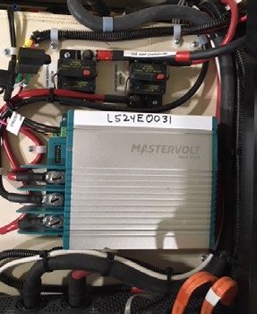
24   LIVING AREA ELECTRICAL SYSTEM            36   MOTORHOME INTERIOR
24   Voltage Chart                            36   Interior Cockpit Map Light
25   AC 110-120 Volt Power                    36   Refrigerator
25   Inverter/Charger                         37   USB Charging Port
26   Inverter Display / Control Panel         37   Solar Panel Package
27   AC Electrical Distribution Panel         38   Table
27   GFCI Outlets                             38   Bed Layout
27   DC Load Center and Breakers              38   Overhead Bunk
29   DC Breakers                              39   Raising and Lowering the Roof
29   12 Volt Battery Disconnect               40   Ladder
29   Charge Line Disconnect                   40   Front Cab Privacy Shades
30   Mastervolt DC-DC Charger
                                              40   Jack and Jack Tools
30   Touchscreen Control Panel and Remote
                                              41   TIRE SAFETY
32   Trouble Shooting the DC/12 Volt System
                                              47   MAINTENANCE LOG
32   Trouble Shooting the AC Power
33   Chassis Battery
33   Coach Batteries
35   Charging Diagram

                                                                                   5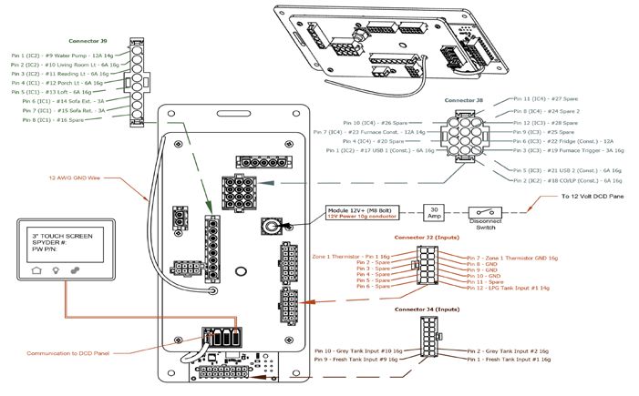
6
WARRANTY / POLICIES
 CUSTOMER RESPONSIBILITY                                             WHAT THIS LIMITED WARRANTY COVERS

It is important you read and understand the information             Pleasure-Way Industries Ltd., warranties the specified new
provided to you in the package containing all the manuals and       Motorhome free from defects in material and craftsmanship
information pertaining to your Pleasure-Way Motorhome.              on portions manufactured by Pleasure-Way Industries Ltd.
                                                                    under normal use and service. Pleasure-Way Industries’
Familiarize yourself with the applicable warranties. You            obligation, under this limited warranty, shall be limited to 60
are responsible for ensuring the procedures for obtaining           months / 60,000 miles / 100,000 kilometers (whichever
warranty repairs are followed properly. It is your responsibility   comes first) after the date of purchase by the first retail
and obligation to return your motorhome to your authorized          purchaser from an Authorized Pleasure-Way Dealer. Warranty
Pleasure-Way dealership for warranty service repairs.               shall be fulfilled by an Authorized Pleasure-Way Dealer or
                                                                    Authorized Pleasure-Way service facility.
As the owner of the Motorhome, you are responsible for
regular and proper maintenance performed in accordance with         This Pleasure-Way Warranty is non-transferable to
the Pleasure-Way and OEM manuals provided. Regular and              subsequent owners.
proper maintenance will help prevent conditions arising from
neglect that are not covered under warranty.

                                                                                                                                1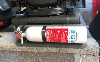
WHAT THIS LIMITED WARRANTY DOES NOT COVER
This limited warranty shall not apply to the following:

    • A Motorhome that has been altered outside our factory in       • Damage caused by the failure to seek and obtain repairs
      any way so as, in our sole opinion and discretion, to affect     in a timely manner.
      its stability, operation or reliability.
                                                                     • Damage caused by the failure to use reasonable efforts to
    • Deterioration due to wear and or exposure, including but         mitigate damage caused by defects.
      not limited to rust: corrosion, oxidation and cosmetic
      blemishes.                                                     • Damage caused by the failure to comply with the
                                                                       instructions set forth in the owner’s manual.
    • A Motorhome that, in our sole opinion and discretion, has
      been subject to misuse, negligence, or accident.               • Goods damaged while stored in exterior storage
                                                                       compartments. Exterior storage compartments may not
    • A Motorhome that has been declared a total loss by an            be moisture free due to weather and humidity conditions.
      insurance company, or a motorhome title indicates it is          It is advised that you store items accordingly.
      designated as “salvage”, “junk”, “rebuilt” or a word of
      similar impact.                                                • Condensation and the results of condensation including,
                                                                       but not limited to, water damage and the growth or mildew
    • The automotive chassis is covered by its own                     or mold. Mold and mildew are natural growths given
      manufacturer’s warranty, including by way of example,            certain environmental conditions and are not covered by
      but not limited to: power train, engine, drive-train, tires      the terms of this warranty.
      and muffler. To learn more about the specific automotive
      chassis not covered under the Pleasure-Way Warranty            • Failure of the coach and /or chassis resulting in incidental
      please contact your authorized selling dealer, Pleasure-         damages, such as but not limited to: goods stored both
      Way Industries Ltd. or review your Mercedes-Benz or Ram          inside and outside the coach; loss of use and equipment
      ProMaster warranty package information provided with             of Motorhome; inconvenience; cost of rental vehicle;
      the coach.                                                       cost of accommodations; travel expenses; towing; meals;
                                                                       and other miscellaneous incidental expenses. Some
    • Appliances and components covered by their own                   states do not allow exclusions or limitation of incidental
      manufacturer’s warranties, including but not limited to:         or consequential damages, so the above limitations or
      the microwave, refrigerator, stove, heater, television,          exclusion may or may not apply to you.
      generator and roof air conditioners. To learn more about
      specific component parts or appliances not covered under
      the Pleasure-Way warranty please contact your selling
      dealer, Pleasure-Way Industries or review your warranty
      package information provided with the coach.

    • Unauthorized repairs, alterations or modifications.

    • Routine maintenance.

    • Items that are working as designed but which you are
      unhappy with because of the design or function.

    • Damages caused by, but not limited to: hail, tornadoes,
      lighting, floods, earthquakes, hurricanes, fire, rain, and
      all other environmental conditions, which include but are
      not limited to, tree sap, tar, chemicals, oils, salts, road
      hazards, stone chips, infestations, rodents and /or acts of
      God.

    • Defects or repairs required, as an example but not
      limited due to; improper loading, load distribution,
      accident, collision, vandalism, abuse, neglect, improper
      maintenance, rust or corrosion.

2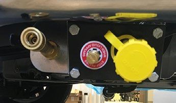
THE CONDITIONS OF THIS LIMITED WARRANTY SHALL                     This warranty is expressly in lieu of all other warranties,
NOT APPLY TO DEGENERATION DUE TO WEAR AND TEAR                    expressed or implied, and all other obligations or liabilities for
AND EXPOSURE AFTER THESE LIMITATIONS                              alleged representation or negligence. Pleasure-Way Industries
                                                                  Ltd. neither assumes nor authorizes any other person to
FOR NINETY (90) DAYS from the original retail                     assume for us any liability in connection with the sale of our
purchase date:                                                    Motorhomes other than expressed above.
 • Adjustments to compartment door latches, light
   bulbs/LEDs, fuses, remote and smoke detector batteries.        All correspondence should be directed to the authorized
                                                                  Pleasure-Way dealer from whom the Motorhome was
FOR ONE (1) YEAR from the original retail date purchase           purchased and must specify the serial number and date of
date or 12,000 miles / 20,000 kilometers (whichever               purchase of Motorhome in question.
comes first), by the original retail purchaser from an
Authorized Pleasure-Way Dealer:                                   Pleasure-Way Industries Ltd. reserves the right to make
 • All seat, curtain, door panel, wall and ceiling fabrics used   changes in Motorhomes built and/or sold by it at any time
   in the coach                                                   without incurring any obligations to make the same or similar
 • Window seals and caulking                                      changes on Motorhomes previously built and/or sold by
                                                                  Pleasure-Way Industries Ltd.
 • Exterior power cable hatch
 • City water fill
                                                                  For emergency repairs while traveling, you may choose to deal
 • Porch light                                                    with non-authorized RV service facilities; however, all warranty
 • Exterior cable TV outlet                                       repairs must be pre-authorized by Pleasure-Way. Pleasure-
 • Carpet                                                         Way will, at its option, replace or repair free of charge any
 • Linoleum                                                       defective part, including labor. The purchaser shall notify their
 • Black and gray water termination valves                        authorized Pleasure-Way Dealer within the warranty period.
 • Exterior striping
                                                                  If you obtain warranty repairs from a non-authorized RV
 • Painted plastic exterior body molding and bumpers.             service facility without Pleasure-Way pre-authorization, it is at
   Painting exterior moldings magnifies the original
                                                                  Pleasure-Way’s sole discretion whether or not to reimburse the
   equipment manufacturer condition of the plastic molding.
   Some conditions of the plastic, such as but not limited to,    claim.
   body attachment points and texture may be more visible
   when painted. These are considered normal.                     In the event that this Motorhome is used for commercial or
                                                                  rental fleet purposes, the warranty coverage shall be limited to
FOR TWO (2) YEARS or 24,000 miles or 40,000                       one (1) year 12,000 miles / 20,000 Km (whichever comes first)
Kilometers (whichever comes first) by the original retail         from the date of original purchase.
purchaser from an Authorized Pleasure-Way Dealer:

 • Foam used in cushions

FOR THREE (3) YEARS or 36,000 miles or 60,000
Kilometers (whichever comes first) by the original retail
purchaser from an Authorized Pleasure-Way Dealer:

 • Exterior painted surfaces

                                                                                                                                3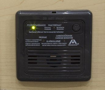
OBTAINING WARRANTY REPAIRS                                          WARRANTY POLICIES

To obtain warranty repairs, you must contact your authorized           Warranty repairs must be with in the five year or 60,000 miles
Pleasure-Way dealer and schedule an appointment. It is best if         / 100,000 kilometers (whichever comes first) limited warranty.
you have a written list of defects or items in need of repair. As
the owner, you are solely responsible for the maintenance of           Pleasure-Way warranty registration cards must be on file
the motorhome as required or recommended by the owner’s                before any claims will be processed. Claims made without
manual and associated costs of that maintenance. Repairs               warranty registration cards will be rejected until proof of
necessitated by failure to maintain the Motorhome as required          ownership can be established.
or recommended are not covered by warranty.
                                                                       Pleasure-Way Industries Ltd. will not reimburse any claims for
NOTE: Pleasure-Way does not control the scheduling of service          work done on any components or appliances that are covered
work at authorized or independent dealerships. You may                 under their respective manufacturer’s warranties. These
encounter some delay in scheduling or completion of work.              warranties must be claimed through the manufacturer of the
                                                                       appliance or component. Examples include but are not limited
                                                                       to: refrigerator, microwave, roof air-conditioning, water pump,
                                                                       furnace, TV etc.

                                                                       All warranty work required to be done on the chassis must
                                                                       be taken to an authorized Ford, Mercedes-Benz, Chrysler
                                                                       or Chevrolet dealership (depending on your chassis make)
                                                                       and processed through their warranty procedures. Pleasure-
                                                                       Way Industries Ltd., will not reimburse any claims regarding
                                                                       the chassis. Pleasure-Way Industries Ltd., will pay for the
                                                                       removal and re-installation of motorhome components only
                                                                       if absolutely necessary to perform Chassis warranty repairs.
                                                                       Pleasure-Way Industries Ltd., will not reimburse any costs in
                                                                       the removal and re-installation of these components if it is: out
                                                                       of the warranty period; non-warranty repairs; and /or routine
                                                                       maintenance or service.

RAM PROMASTER WARRANTY USA                BASIC LIMITED WARRANTY – coverage for 3 years or 36,000 miles

                                          POWERTRAIN LIMITED WARRANTY – coverage for 5 years or 60,000 miles

                                          ROADSIDE ASSISTANCE - coverage for 5 years or 60,000 miles

RAM PROMASTER WARRANTY CANADA             BASIC LIMITED WARRANTY – coverage 3 years or 60,000 kms

                                          POWERTRAIN LIMITED WARRANTY – coverage for 5 years or 100,000 kms

                                          ROADSIDE ASSISTANCE - coverage for 5 years or 100,000 kms

4
5
SAFETY
    For your safety while traveling with your Pleasure-Way             All Pleasure-Way Motorhomes in Canada are CSA (through
    motorhome, we have provided safety components throughout           QAI) and CMVSS certified, and may exceed the approved
    the vehicle. In order for your vehicle to maintain the safest      installation criteria.
    possible conditions, these components must be tested and
    maintained on a regular basis, according to the detailed           All Pleasure-Way Motorhomes in the United States are
    manufacturer’s operating instructions.                             FMVSS certified and bear the R.V.I.A. seal of approval, and
                                                                       may exceed the individual state requirements.

    OCCUPANT AND CARGO CARRYING CAPACITY
    The Tire and Loading Information label, found on the driver
    side door pillar, states the OCCC of your motorhome. This
    figure states the maximum allowable weight of all occupants
    (including the driver), plus the weight of all food, tools, full
    fresh water tanks, and personal belongings. The tongue
    weight of a towed trailer also counts as cargo. If you are
    traveling with water in your holding tank, weight can be
    calculated by using this ratio: 1 kg/L or 8.3 lb/gal.

    The OCCC of your motorhome was calculated by adding
    the weight of: the full LP fuel tank, the full vehicle fuel tank
    and the dry weight of the motorhome (as shipped from the
    factory) and subtracting that number from the Gross Vehicle
    Weight Rating (GVWR).

    NOTE: All US units include a second OCCC label on the inside
    of the passenger door.

    SMOKE DETECTOR
      A smoke detector is located in the overhead bunk.
      Smoke detectors may give you a warning of fire and
      smoke, but only if used and maintained in accordance to
      the manufacturer’s instructions.
    • This device should be tested after each time your vehicle
      has been in storage, before each trip, and at least once
      each week during your travels.

    • Do not block air circulation in the area where the smoke
      detector is located.

    • Ensure you connect the battery inside the detector upon
      receiving your new unit.
      (9 volt battery located inside the unit.)

    • Install a fully charged fresh battery at least once a year.

    WARNING: Before operating the cooktop, the roof must be
    in the raised position.

6
FIRE EXTINGUISHER
A 3-pound capacity fire extinguisher is provided and located
at the side door main entrance for ease of accessibility from
the interior or exterior.
WARNING: This fire extinguisher is a type “ABC”, which will
extinguish flammable liquids and electrical fires, but not wood,
paper and cloth fires. You should inspect the extinguisher
at least once a month according to the manufacturer’s
instructions.
LP/CARBON MONOXIDE DETECTOR
A liquid propane (LP) / carbon monoxide (CO) gas detector is
located near the floor level below the driver side of sofa bed.
This detector will detect liquid propane gas, carbon monoxide
and other gases that are heavier than air. The detector is
powered by the coach batteries and will only operate when
the 12 volt battery disconnect switch is ON.
The detector should be tested after each time your vehicle
has been in storage, before each trip, and weekly while the
vehicle is in use. The test procedure should be performed in
accordance to manufacturer’s instructions. Do not block air
circulation in the area where the detector is located.
NOTE: The LP/CO detector will sound to indicate a low coach
battery voltage.
GFCI OUTLET
A ground fault circuit interrupter (GFCI) 110-volt receptacle
located kitchen face frame below the sink provides protection
against line-to-ground electrical shock hazards that could
be harmful or even fatal. The outlets that are on this circuit
are the exterior, kitchen and rear bench receptacles. The
GFCI receptacle must be tested at least once a month in
accordance with the manufacturer’s instructions.
The GFCI for the Induction Stove is found in the cabinet
below the induction cook top.
7REFUELING
When refueling your fuel tank or your propane system,
ensure that your vehicle and your main LP valve is shut off.
Ensure that the pilot lights have been extinguished as well.
Some appliances in your vehicle have auto ignition. Ensure
the appliances are shut off so ignition will not activate.
WARNING: Even with the main LP valve shut off, there is
enough LP gas in the lines to cause the pilot lights to continue
to burn.
FILLING THE LP GAS FUEL CYLINDER
The propane tank valve must be closed and all pilot lights
and appliances, along with their igniters, must be turned off
during refueling of the motor fuel and/or the propane fuel
tank. Only qualified personnel should refuel your propane
tank. Do not refuel the propane tank to more than 80% of its
capacity. Liquid will appear at the breather valve at 80%.
To reduce the danger of fire and/or explosion, do not store
gasoline or other flammable liquids inside your vehicle.
NOTE: When the tank reaches 80% capacity the LPG gauge
on the touchscreen control panel will read 100%.
WARNING: Ensure the propane system valve is fully shut
when the vehicle is in motion. It is not safe to travel while
propane appliances are in use. The propane switch is located
in the driver side utility center.
APPLIANCES
It is not safe to use cooking appliances to heat the interior
of the coach due to the danger of asphyxiation. It is
recommended that you read all of the appliance owner /
operating manuals prior to using the appliances.
(for more information see page 18)
8ROAD SAFETY STRAP
The roof must be lowered and the latches and safety strap
locked in place before moving the vehicle. The safety latch
much remain locked while the vehicle is in motion.
SEAT BELTS
Only forward-facing seats equipped with factory installed
seatbelts are to be occupied while the vehicle is in motion.
All passengers must be seated in these seats only. Seat belts
must be fastened while the vehicle is in motion.
Your vehicle is equipped with three point seat belts on the
front Driver and Passenger seats, as well as two lap belts
on the rear sofa seat. In order for passengers to ride in the
rear of this vehicle, the rear sofa must be in the full upright
position and seat belts must be secured.
VEHICLE GROUND CLEARANCE
Your motorhome is equipped with underside holding tanks,
drainage lines, propane lines and other RV related items.
Please be careful when driving your motorhome on uneven or
poorly maintained roadways.
EMERGENCY ESCAPE
To make an emergency escape from your motorhome, use
the interior door handle available on all doors.
9MOTORHOME EXTERIOR
MOTORHOME SPECIFICATIONS
Your motorhome is larger than your standard van or
automobile, so please be careful when entering underpasses,
garages, parkades, etc.
3.6 litre Pentastar V6 featuring 280 HP / 260 LB-FT Torque
6 Speed Automatic Transmission
220 Amp Alternator
Class IV Hitch and Wiring
136” Wheel Base with 40.7 Turning Diameter
PROMASTER PAINT CODE:
Deep Cherry Red: PRP, Granite Crystal: PAU, Bright Silver:PS2
DIMENSIONS
Length Bumper to Bumper 17’ 9” 541 cm
Height without Roof Rack 8’ 2” 249 cm
Height with Roof Rack 8’ 6.5” 260 cm
Width with Mirrors Extended 8’ 2.5” 269 cm
Width with Mirrors Retracted 7’ 6” 228.6 cm
Queen Bed 54”(wide) x 72”(long)
Overhead Bunk 49”(wide) x 72”(long)
CAPACITIES WEIGHT
Fuel 24 US gallons / 90 L 149.3 lbs
Fresh Water / Potable Water 16 US gallons / 60.6 L 133.4 lbs
Grey Water (sink) 8 US gallons / 30.3 L 66.7 lbs
Liquid Propane LPG (at 80%) 5.9 US gallons / 22.3 L 24.8 lbs
Roof Rack Weight Capacity 200 lbs 90.7 kg
Overhead Bunk Weight Capacity 200 lbs 90.7 kg
Ladder Weight Capacity 330 lbs 150 kg
Towing Capacity 2950 lbs 1338.1 kg
Seat Belts 4
10CHASSIS SPECS - RAM PROMASTER 1500
GVWR 8,550 lbs 3,879 kgs
GCWR 11,500 lbs 5,216 kgs
GAWR Front 4,629 lbs 2,100 kgs
GAWR Rear 5,291 lbs 2,400 kgs
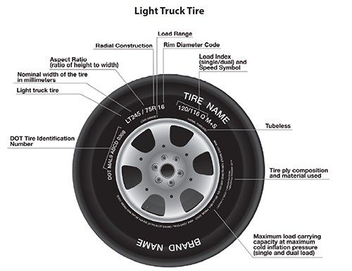
Tires (All) LT 225/75R 16 E 10 Ply with an E weight rating
Tire Pressure Front 65 PSI 450 KPA
Tire Pressure Rear 80 PSI 550 KPA
APPLIANCES MANUFACTURER MODEL
AC/DC 2.3 cu ft. Fridge Dometic AC/DC CRX 1065
Induction Cook Top True Induction TI-1B
Water Pump Shurflo 4008-101-A65
Furnace Atwood AFSD16121
Solar Panel Go Power Flex 100
Solar Control Go Power GP- PWM - 30
Inverter / Charger Xantrex Freedom XC 2000 817-2080
DC to DC Charger Mastervolt Mac Plus 12/12-50
In Dash Stereo Ram Promaster U Connect 3 Nav - 5” display
LP Solenoid Manchester MED-Teneca
Ceiling Lights Kaper II L09-0113
Porch Light Optronics Inc. ILL70CBBAWN
LP/CO Detector Atwood 31011
Dual Coach Batteries Life PO4 ECO-ION Lithium 100AH
NOTE: All measurements and capacities are approximations. Every effort has been made to be as accurate as possible.
PLEASE NOTE:
• Appliances and options may change without notice and some appliances and equipment may be optional.
• Due to Pleasure-Way’s policy of continuous improvement, Pleasure-Way Industries Ltd. reserves the right to make product changes at any
time without incurring obligation.
• The chassis manufacturer may make mechanical and option changes without Pleasure-Way Industries Ltd. incurring any obligation.
• Pleasure-Way Industries Ltd. cannot be held responsible for changes made to an appliance supplied by another distributor or manufacturer.
• Pleasure-Way Industries Ltd. cannot be held responsible for dealer installed options.
11TIRE AND LOADING INFORMATION The tire load information is located on the driver side door pillar. Please check the label on your vehicle for exact tire pressures and Occupant and Cargo Carrying Capacity (OCCC). PROPANE FILL, BREATHER VALVE AND BBQ QUICK CONNECT The fill and breather valve is located below the passenger side running board under the sliding door. The BBQ quick connect is located on the right hand side of the LP breather. (for more information see page 17) SEWER DUMP COMPARTMENT Located in the driver side, open the driver side rear door and hose container to access the sewer hose. Open the cap on the sewer discharge. Attach the sewer hose to the sewer discharge and to a sewer dump sight. Pull the grey gate valve handle to drain the tank. Disconnect and flush the blue sewer hose, return the sewer hose to the storage container, close the grey water handle and close the sewer cap. UTILITY CENTER Located on the driver side exterior, this compartment 1 2 3 contains three main components used in your RV: 1. Shore Power Hook-Up 2. LP Electric Valve Switch 3. Pressurized City Water Hook-Up FRESH WATER HOLDING TANK FILL Located on the driver side exterior, this compartment allows you to fill the fresh water holding tank. It also contains the vent tube for your fresh water holding tank. 12
FURNACE VENT
Located on the driver side exterior, this vent gives off the
exhaust of the furnace.

NOTE: Ensure this vent is free and clear of any obstructions
at all times.

EXTERIOR 110-VOLT PLUG
Located on the passenger side panel behind the rear wheel,
this plug will only function if power is supplied through the
inverter or shore power. This plug is controlled by the GFCI on
the kitchen face frame.

PORCH LIGHT
Located on the touchscreen control panel on the kitchen face
frame or the hand held remote. Select the porch light button
to turn on or off the porch light. This button will be on the
home screen.

SOLAR PANEL PACKAGE
Your vehicle can be equipped with 95 to 190 watt Go Power
solar panels. The solar panels are located on the rear of
the pop top. The charge control panel is located above the
kitchen countertop.
(for more information see page 35 & 37)

ROOF RACK (MAXIMUM WEIGHT 200 LBS)
To adjust the cross rails use a 5/32” Allen wrench to loosen
the two Allen machine bolts on the cross rail foot. Slide the
rail to the location that is needed and tighten the bolts.
WARNING: When raising or lowering the roof ensure no items
are on the roof rack. The roof rack is only to be used when the
roof of the vehicle is in the lowered position with the spring
latches engaged and the safety strap connected.

                                                                  13
MAINTAINING YOUR MOTORHOME It is recommended that you regularly maintain your Pleasure-Way Motorhome in order to get the maximum benefits from your unit. The life and performance of each component depends upon proper use, operation and maintenance. With a regular maintenance schedule you should be able to identify any components that may need attention, allowing you to have many years and miles of trouble-free traveling. NOTE: Please refer to your Ram ProMaster owner’s manual for chassis mechanical maintenance. HELPFUL HINTS To maintain your exterior painted fiberglass and metal surfaces we suggest you thoroughly clean and wax these pieces regularly. All fiberglass surfaces are painted with automotive paint. When storing your Pleasure-Way motorhome it is recommended that you park the vehicle on a level surface. Avoid parking in a front end down position as rain or snow may collect in the air conditioner area, allowing moisture to enter the vehicle through the air conditioner. Damage to the motorhome as a result of incorrect parking will not be covered under warranty. When storing your Pleasure-Way motorhome, ensure all holding tanks are emptied and flushed, the water system is completely drained, including the water heater, the LP gas valve is turned off, the 12 volt battery disconnect is switched to the OFF position, and all electrical appliances are turned off. When storing your Pleasure-Way motorhome it is recommended that you run your vehicle engine once a month to allow the engine starting battery to recharge and the vehicle fluids to flow through the engine. Please refer to your vehicle operation manual for more details. 14
TRAVEL PREPARATION

BEFORE YOU LEAVE
Prior to heading off on your adventures, you should always
check to ensure that:

• The LP gas is turned OFF at the main valve
• The gray waste water tank is empty with the dump
 handles closed
• All electrical cords and exterior hoses are stored back into
 their respective compartments
• Chassis fluid levels are at recommended levels
• Chassis tire pressure levels are at recommended levels
• Chassis exterior lighting is functional
• All exterior components are secure and closed
• All interior compartments and drawers are closed
 and latched
• All interior components are secure and in place
• The furnace control switch is off
• The site is left in better condition than when you arrived

WHILE IN MOTION                                                  UPON ARRIVAL AT YOUR SITE
While in motion, refrigerator can operate in DC mode.            Once you arrive at a site, please ensure that:
Use of any other appliance is not recommended while the
                                                                 • Your motorhome is parked in a level position so that your
motorhome is in motion.
                                                                   components will perform optimally (place a bubble level on the
                                                                   freezer shelf of the refrigerator and level your unit accordingly).
Always wear your seat belt when the vehicle is in motion.
Only forward facing seats are equipped with seat belts.          • All exterior vents are clear from obstructions

                                                                 • The gray water waste tank valve is closed
WARNING: Do not use LP appliances while the vehicle is in
motion.                                                          • The AC power cord is attached to the vehicle and to the site
                                                                   receptacle (120 volt 30 amp)

                                                                 • You hook the fresh water line to the city connection or fill the
                                                                   fresh water tank and turn on your water pump

                                                                 • The LP gas switch is turned ON

                                                                                                                                      15
MOTORHOME SYSTEMS
LIQUID PROPANE GAS SYSTEM
LP appliances are: Furnace and BBQ Quick Connect
Your motorhome is equipped with a Liquid Propane (LP) gas
system that provides a fuel source to the appliances which
are designed to use this gas for operation. The storage tank
is located under the chassis on passenger side. Access to
the LP tank and regulator is found under the vehicle. The
regulator is on the passenger side propane tank bracket.
An LP gas regulator must always be installed with the
diaphragm vent facing downward. Regulators that are not
in compartments have been equipped with a protective
cover. Make sure that the regulator vent faces downward
and that the cover is kept in place to minimize vent blockage
that could result in excessive gas pressure, causing fire or
explosion. The main propane shut-off switch is located in the
driver side utility center.
The propane fill, breather valve and BBQ quick connect are
located below the running board on the passenger side. The
breather valve must be open to fill the propane tank.
Liquid will appear through the breather valve when the tank is
80% full.
The propane gage is located inside your coach on the
touchscreen panel. The panel will indicate full or 100% when
the LP tank is 80% full.
NOTE: Your LP gas appliances may not light on the first try.
There may be air in the LP gas lines that will dissipate as the
gas pressurizes the lines.
WARNING: Do not bring or store LP gas containers, gasoline
or other flammable liquids inside the vehicle because a fire
or explosion may result. LP gas containers are equipped with
IF YOU SMELL GAS: safety devices that relieve excessive pressure by discharging
1. Extinguish open flames, pilot lights and smoking materials gas into the atmosphere.
2. Do not touch any electrical switches WARNING: It is not safe to use cooking appliances for
3. Shut off the gas supply at the tank valve or at the gas comfort heating. Cooking appliances need fresh air for safe
supply connection operation. Unlike homes, the amount of oxygen supply in the
unit is limited due to the size of the vehicle. Proper ventilation
4. Open all the doors and other ventilating openings when using the cooking appliance(s) will avoid the dangers of
5. Leave the area until the odor clears and you are sure asphyxiation, explosion and CO poisoning.
there is no further risk to you or others
WARNING: Do not use portable fuel burning equipment,
6. Have the gas system checked and leakage source including wood and charcoal grills and stoves inside the
corrected before using again motorhome. The use of this equipment inside the recreational
vehicle may cause fire or asphyxiation.
16LP TANK GAUGE
This gauge indicates how full the LP tank is. The LP gauge is
located on the tank with a sending unit that sends levels to
the touchscreen control panels.
LP FILL VALVE & LP BLEEDER VALVE
The bleeder valve allows pressure to vacate the LP tank when
80% full. The fill valve, is covered by the yellow end cap.
Only fill the LP tank to 80% capacity, liquid will appear from
the breather valve at 80%.
WARNING: DO NOT FILL LP CONTAINER TO MORE THAN
80% CAPACITY. Overfilling the LP gas container can result in
uncontrolled gas flow, which can cause a fire or explosion. A
properly filled container will contain approximately 80% of its
volume of LP gas.
BBQ QUICK CONNECT
The BBQ quick connect is directly connected to the RV LP
system. It is equipped with it’s own shut-off valve (black
handle). The quick connect is a regulated (low pressure)
LP line that is supplied from the onboard LP tank. The BBQ
quick connect works with the standard, full-flow male quick
connect fitting. You will need a BBQ that is set-up for a low
pressure LP source.
BASIC OPERATION:
1. Ensure the black valve is in the OFF position.
2. Remove the yellow cap and ensure the opening is clean.
3. Pull the sleeve of quick connect back and insert the
male quick connect fitting.
4. Push the male fitting until the sleeve snaps forward,
locking the fitting into the socket.
5. Connect your BBQ.
*LP hose and BBQ not included.
6. Turn the black valve ON to allow propane to flow to the
connected BBQ.
7. Ensure the main LP switch in the Utility Center is ON.
NOTE: Propane will only flow from the BBQ quick connect
when there is a hose connected. This is a safety feature of this
component. The black valve must be in the OFF position to
release the hose from the quick connect.
17HOW TO USE THE LP APPLIANCES
Turn ON the 12 volt battery disconnect switch.
(located on the lower sofa bench.)
Turn ON the LP electric valve.
(located in the driver side utility center)
FURNACE
Please refer to the manufacturer’s operating instructions for
further information.
Your vehicle is equipped with a 16,000 BTU Atwood LP gas
Auto Ignition Furnace. The furnace is located near the floor
next to the fridge.
1. Ensure that there is propane supplied to the coach.
2. Ensure there is 12V power to the coach.
3. Select the thermometer icon on the touchscreen
control panel.
4. Use the up and down arrows to select the
desired temperature.
5. The furnace fan will come on, the furnace will auto
ignite and cycle through the fan and heating process.
The furnace will maintain the desired temperature.
6. The furnace reset button is located under the kitchen
shelf. Slide the shelf above the furnace to the right by
pressing down on the right edge next to the divider.
COOKTOP
Please refer to the manufacturer’s operating instructions for
further information.
The vehicle is equipped with a single burner flush mount
induction cooktop located in the kitchen countertop.
Power, heating and timer controls are located under the
burner. A GFCI for the cooktop is located on the kitchen face
frame below the cooktop.
18FRESH WATER SYSTEM
The water system built into your motorhome provides full
service similar to the system in your home. A 12-Volt self-
priming pump draws pressurized water from the fresh water
tank to all cold faucets and rear quick connect sprayer.
An automatic pressure switch located in the water pump
maintains a positive line pressure between 20 to 30 psi.
The fresh and gray water tanks are located underneath the
kitchen cabinet next to the sofa.
FRESH WATER FILL AND DRAIN
To fill the fresh water tank, use the gravity water fill located
on the driver side of the van. First, unlock the water fill
compartment and remove the large cap; then place the water
hose into the fill. Turn on the water to medium flow.
There are two ways of knowing when your water tank is full:
1. Check the monitor panel located inside your coach
2. When water flows back through the gravity fill.
NOTE: If you notice water running out from underneath the
van, check the drain tap under the passenger side running
board. This tap is there to help you drain your fresh water tank.
FRESH WATER SYSTEM DRAIN
The fresh water tank drain (white line) is located under the
driver side running board. This drain is connected directly
to your fresh water tank and will allow you to drain the fresh
water tank when the vehicle is not in use. To use this drain
ensure all water taps are in an open position.
LOW POINT DRAIN VALVE
The vehicle is also equipped with a low point drain valve (blue
line). This valve will allow you to drain all the fresh water lines
in the vehicle. The low point drain is located below the driver
side running board next to the fresh water tank drain. To use
this drain ensure all water taps are in an open position.
19WATER PUMP AND TROUBLE SHOOTING Located in the cabinet below the kitchen sink. The water pump has a removable filter that should be checked regularly. The inline flow filter is located on the inlet side of the water pump. If the pump will not prime, ensure: • Water is in the holding tank • The battery is not run down • Water lines are tightly connected to the pump and to the filter • There are no leaks at the inlet fitting and filter (if air is leaking into inlet fittings, tighten fittings or apply clamps as necessary) • The inline flow filter is clean If the water pressure drops, ensure that: • Faucet aerators are clean • There is water in the holding tank • Battery is not run down • Faucets and connections are free of leaks If the pump runs when there is no apparent demand for water, ensure that: • Water in the holding tank • All faucets and fixtures are shut off and not leaking • Water lines are free of leaks CITY WATER CONNECTION The city water connection is located in the driver side utility center. The city water connection is a convenience for you when you have access to an outside, pressurized water source. To hook up the city water connection you should make sure that the water pump switch is turned off inside the coach and that all faucets are shut. Attach your water hose and turn on the water supply. The city water system bypasses the fresh water holding tank and feeds the water lines directly so that you will not have to use the water pump. To disconnect the city water system, first turn off the water source, then open a faucet to relieve some of the pressure in the lines and then unhook the water line. NOTE: It is advisable to use a water pressure regulator. Excessive pressure may result in water line damage. 20
KITCHEN FAUCET
Huntington Brass - K1102701
With the faucet handle turned off, the faucet may continue
to drip for a short period of time or when the vehicle is
motion. Water is retained in the faucet spout.

SPRAY PORT & HOSE
Access to this spray port is through the passenger rear door,
located in the rear storage area. This port is to be used on
city water or when the water pump is in the on position.

WASTE SYSTEM
A grey water tank is located on the driver side of the vehicle
below the kitchen cabinet. This tank holds wastewater from
the sink. This tank is approximately 8 gal / 33.3 L.

SEWER HOSE & GATE VALVE DRAIN CONNECTION
Located in the driver side rear bench, open the driver side
rear door and hose container to access the sewer hose.
Open the cap on the sewer discharge. Attach the sewer hose
to the sewer discharge and to a sewer dump sight.
Pull the grey gate valve handle to drain the tank. Disconnect
and flush the blue sewer hose, return the sewer hose to the
storage container, close the grey water handle and close the
sewer cap.
NOTE: If the grey water tank is allowed to overfill, the overflow
may back up through the sink drain

NOTE: If you are using a sewer hookup in a RV park, keep
the valve closed until the holding tank is at least partially full,
then drain. The large quantity of waste flow will provide more
effective drainage and reduce tank stoppages.

                                                                      21
WINTERIZING
WINTERIZING THE WATER SYSTEM
1. To drain the fresh water tank, open the white drain tap.
2. Drain and flush the grey water holding tank.
3. Remove the water line from the inlet side of the water
pump (this is the plastic line going into the water pump
filter). Connect a siphon hose to the inlet side of the
water pump and place the other end in a container of
non-toxic, RV antifreeze. Turn on the water pump. This
will pump non-toxic, RV antifreeze through all of your
fresh water lines.
4. Open the kitchen faucet and connect the spray port
hose allowing the antifreeze to flow through the faucet
and hose.
5. Pour ½ cup of non-toxic, RV antifreeze down the kitchen
sink drain.
6. Open your grey water tank valve one last time to ensure
all water from the holding tank is completely drained.
Once drained, close your grey water tank valve
for winter.
NOTE: Siphon hose consists of 40” of ½” clear tubing with
a fitting to attach to the water pump. The fitting can be
purchased through an RV dealer.
OPTIONAL WINTERIZING FOR MILDER CLIMATES
1. Open the low point drain valve (blue line).
2. Connect a blowout valve to the city water inlet.
Connect a compressed air source.
3. Open the kitchen faucet. Allow the air to blow the
remaining water out of the taps and valves. Fully drain
the system. Leave the kitchen faucet and low point
drain in an open position.
4. Pour ½ cup of non-toxic, RV antifreeze down the sink.
22WINTER STORAGE ELECTRICAL
1. Fully charge the engine starting and coach batteries.
2. Turn OFF the charge line disconnect switch (red key).
3. Turn off the battery disconnect switch on the sofa.
• It is recommended that you start and run your vehicle
for a short period of time each month.
• It is recommended that the fridge door be left slightly
open to allow air to circulate through the fridge cabinet
during a storage period.
• It is recommended that the vehicle be driven or moved
forward or backward, if possible, to avoid flat spotting
of the vehicle tires.
• The lithium ion batteries should not be charged if the
interior of the coach is below freezing (32 F or 0 c)
WINTER USE
We recommend that the water system not be used when NOTE: Keep in mind that as you add more water to the holding
the outside temperature drops below the freezing point. You tanks the antifreeze will dilute beyond the recommended
should ensure that your unit is completely winterized by that amount and may start to freeze earlier at cold temperatures.
time. If it is necessary to use the water system, we suggest
that you bring containers of fresh water with you and add
non-toxic, RV antifreeze to the gray water holding tanks.
23LIVING AREA ELECTRICAL SYSTEM
The motorhome living area, electrical system is designed 12 VOLT OR DC EQUIPMENT
for convenience. It is capable of supplying the vehicle Inverter/Charger
with at least two sources of power: 12 volt DC power and
Refrigerator when on DC
110-120 volt AC power. The 12 volt coach battery supplies
power to the interior components for dry camping use. The Interior & Exterior Coach Lights
12 volt or DC, power supplies an AC 110-120 volt current to Water Pump
the interior plug outlets through the 2000 watt Pure-sine LP Gas & CO Alarms
wave inverter. Furnace
The coach batteries are charged when the chassis engine is Touchscreen Control Panel
running and the charge line disconnect switch (red key) is USB Port
in the ON position or when you are connected to a 110-120
volt power source (shore power) and with the 12 volt
110-120 VOLT OR AC EQUIPMENT
battery disconnect switch in the ON position. Your vehicle
may also be equipped with solar panels. These solar panels Induction Cook Top
will charge the coach batteries if the charge line disconnect Refrigerator on AC
switch (red key) is in the ON position.
110 Volt Plugs When on a Shore Power Source
For long term use, your vehicle may be powered by
plugging into a 110-120 volt external power source with NOTE: All dash components including the in-dash radio and
the supplied 25 foot power cable. The 25 foot power cable front map lights are powered through the starting (chassis)
supplied with your coach must be connected and locked to battery. Prolonged use of these items when the vehicle is not
your coach and then to a 110-120 volt power source (a 30 running will deplete the engine starting battery.
amp outlet is recommended). This will supply 110-120 volt
power throughout the interior and supply power through
the inverter/charger to all 12 volt components.
Your motorhome is equipped with a Pure-sine wave 2000
watt Xantrex Freedom XC Inverter/Charger. The charging
portion of the Freedom XC is set to LFP to charge the
coach batteries. The freedom XC also converts 110 volt into
12 volt to operate 12 volt appliances when plugged into
110-120 volt power.
Your motorhome is also equipped with a 2000 watt Pure-
sine wave inverter. The inverter takes the 12 volt or DC
power from your batteries and inverts it up to 110-120 volt
AC power. The inverter will enable you to use your 110-
120 volt plug outlets and induction cook top when a shore
power source is unavailable. This power source will be
limited by the state of charge of your batteries and by the
amount of current drawn by each appliance. The inverter
has a built in transfer switch that allows the 110-120 volt
power to bypass the inverter and power the 110-120 volt
plug outlets and induction cook top when the motorhome
is plugged into a shore power source.
24AC 110-120 VOLT POWER
A 25 foot, 30 amp power cord is provided on the rear door.
To activate all power circuits, connect and lock the power
cord to your coach in the driver side utility center and to
an adequate 110-120 volt power source. The power cord
connections are rated for 30-amp 110-120 volts.
NOTE: The male end of the power cord is a 30-amp style
plug, therefore you may require an adapter to convert the plug
into the 110-15 amp style. Most RV parks are equipped with
30-amp outlets. Remember to always attach the power cord
to your coach first, and then to the power source.
WARNING: Ensure the power source for your vehicle is a 110-
120 volt power source. A higher voltage or lower voltage outlet
could do damage to your coach.
INVERTER/CHARGER
Please refer to the manufacturer’s operating instructions for
further information.
Your vehicle is equipped with the Xantrex Freedom XC 2000
watt Pure-sine wave inverter located below sofa bed. This
inverter provides 12 volt DC power inverted to 110-120 volt
AC power for the induction cooktop and all AC outlets in and
outside the coach.
The charging portion of the inverter is set to LFP to charge
the coach batteries. The inverter also converts 110 volt into
12 volt to operate 12 volt appliances when plugged into
110/120 volt power.
The inverter will be limited by the state of charge of the coach
batteries and amperage draw from individual appliances.
It has an automatic transfer switch built into it, so that if you
are on shore power it bypasses the inverter.
The inverter will draw .6 amps of DC power if it is turned on
and no load is being drawn from the inverter. If no load is on
the inverter it will turn itself off after 25 hours of continual
operation. The inverter is powered by the large red wires in
the battery compartment. There is also a 250 amp mega-
fuse in the system to protect the inverter and the coach.
CAUTION: Ensure all venting for the inverter is kept clear
of blockage.
25INVERTER DISPLAY / CONTROL PANEL
This control panel is located on the kitchen upper end panel
next to the switch panel.
• This control panel will turn the inverter ON or OFF
• Neither the 12 volt battery disconnect nor the charge line
disconnect will turn the inverter off
• Always make sure the inverter is in the OFF position when
Freedom XC Series INV-CHG Owners Guide.book Page 40 Monday, April 9, 2018 2:29 PM
not in use
• The inverter can draw .6 amps from your battery if left in
Inverter
the and Charger
ON position while Operation
not in use
Function Buttons
NOTE: To turn the inverter ON or OFF you must press and
LCD Screen
hold the power button on the inverter control panel for at The LCD Screen changes depending on the operating mode of the
Button
least Definition
1 second. inverter.
return to default screen or exit setting mode
AC IN or AC OUT indicator
next screen or next selection left LCD display middle LCD right LCD
Freedom XC Series INV-CHG Owners Guide.book Page 40 Monday, April 9, 2018 2:29 PM display display
to enter the setting mode or to confirm the setting alarm off
indicator
turns on inverter/charger operation or to Standby
Inverter andmode
Charger Operation INPUTBATTTEMP OUTPUTBATTLOAD
kW kW
AC VA VA
Function Buttons LCD Screen %C ERROR
%
Hz Hz
The LCD Screen changes depending on the operating mode of the
BYPASS
Button Definition inverter. OVERLOAD
return to default screen or exit setting mode 100%
Freedom XC Series INV-CHG Owners Guide.book Page 39 Monday, April 9, 2018 2:29 PM AC IN or AC OUT indicator
next screen or next selection left LCD display middle LCD right LCD
display 25% display
to enter the setting mode or to confirm the setting CHARGING alarm off
indicator
turns on inverter/charger operation or to Standby load power
Inverter and Charger Operation
mode battery level
INPUTBATTTEMP OUTPUTBATTLOAD
level indicator
indicator indicator
mode kW load indicator kW
AC VA VA
%C ERROR
%
Figure 11 Parts of the LCD
Hz Screen Hz
Freedom XC Display Panel Status LED Indicators
BYPASS
Indicator Definition OVERLOAD
Status LED indicators
Indicates grid mode in which shore power is 100%
40 solid green
Freedom XC Owner’s
available and passing through to the loads Guide
and charging the battery. 25%
CHARGING
Indicates Battery mode (Inverter mode) in
INPUTBATTTEMP OUTPUTBATTLOAD
888 88 888
kW kW
AC VA VA
%C
Hz
ERROR
%
Hz Function buttons
BYPASS
solid green
which the inverter is running and supplyingload power
OVERLOAD
ESC button mode battery level
power to the loads indicator
from the battery.
100%
indicator level indicato
25%
CHARGING
Scroll button load indicator
LCD
Indicates error or fault mode and is
Screen OK button
solid red accompanied by an error code displayed on
Figure 11 Parts of the LCD Screen
Power button
the LCD screen. For a list of error codes,
see “Warning Messages” on page 64.
Figure 10 Display Panel Indicates a Warning condition and is
flashing
red accompanied by an error code and a
sounding alarm. For a list of error codes,
40 see “Warning Messages” Freedomon pageXC 64.Owner’s Guid
26AC ELECTRICAL DISTRIBUTION PANEL
The Pleasure-Way Tofino is equipped with an AC distribution
panel that houses the breakers for the 110-120 volt system.
The distribution panel is located on the driver storage
compartment wall. The breakers act like a household breaker;
you must insure the breaker is shut all the way off before you
can reset the breaker.
1. 30 Amp Inverter Input
2. 15 Amp Refrigerator
3. 30 Amp Shore Power
4. 30 Amp Inverter Output
5. 20 Amp Induction Cooktop (GFCI protected)
6. 15 Amp Receptacles (GFCI protected)
GFCI OUTLETS
A ground fault circuit interrupter (GFCI) 110-volt receptacle
located kitchen face frame below the sink provides protection
against line-to-ground electrical shock hazards that could
be harmful or even fatal. The outlets that are on this circuit
are the exterior, kitchen and rear bench receptacles. The
GFCI receptacle must be tested at least once a month in NOTE: The circuits must be powered to test or reset the GFCI.
accordance with the manufacturer’s instructions. Check the GFCI for the individual appliance or plug outlets if
the appliance is not operational.
The GFCI for the induction stove is found on the cabinet face
below the cooktop.
DC LOAD CENTER AND DC BREAKERS
This load center is located in the cabinet in the driver side
storage area. This DC load center controls all the multiplex
wiring systems and switch panels.
This load center also has resettable breakers that can be
reset from the kitchen touchscreen control panel.
1. Select > SETTINGS
2. Select > SYSTEM SET UP AND DIAGNOSTICS
3. Select the appliance you want to turn off or reset
27DC LOAD CENTER BOARD (SPYDER CONTROLS) 28
DC BREAKERS
These are resettable breakers. When a breaker is tripped a
black lever will swing out below the center bar. To reset the
breaker push the lever back up under the center bar.
To manually trip a breaker, press the red button.

80 AMP INPUT AND OUTPUT BREAKERS FOR THE                          80 AMP CHARGER OUTPUT
MASTERVOLT DC-DC CHARGER
These are located on top of the coach battery box under the
cover panel next to the charge line disconnect switch
(red key). The 80 Amp Input breaker will disconnect the
charge line (from the alternator) to the Mastervolt DC-DC         80 AMP CHARGER INPUT
Charger. The 80 Amp Output breaker will disconnect the
Mastervolt DC-DC Charger to the charge line disconnect
switch as well as the coach batteries.

12 VOLT BATTERY DISCONNECT
There is 12 volt battery disconnect switch located on the
face frame of the sofa. This switch will stop all 12 volt power
supplied to your coach from the auxiliary batteries.

The disconnect switch will have to be in the ON position in
order to charge your battery from the coach batteries.

NOTE: If your vehicle is going to be parked and not in use
for longer than a 48 hour period, turn this switch to the OFF
position as the LP/CO detector is hard wired into the coach
batteries and will eventually drain the batteries.

CHARGE LINE DISCONNECT
The charge line disconnect switch (red key) is located on the
lower front of the sofa. The charge line disconnect switch
controls the charge from the engine alternator and solar
panels to the coach batteries. When the switch is ON, the
coach batteries will charge from the engine alternator and
solar panels. When the switch is OFF, the coach batteries will
NOT charge from the engine alternator and solar panels. This
disconnect switch is used for shipping, storage and freezing
conditions. Turn the switch OFF during battery servicing.
ON Position: red key is locked into the switch
OFF Position: red key can be removed from the switch

                                                                                         29
MASTERVOLT DC-DC CHARGER The DC-DC charger is located under the sofa, mounted next to the inverter/charger. The DC-DC charger takes 12 volt charge from the alternator and converts it to optimal charging for the coach batteries. The DC-DC charger has a 2 amp trigger fuse located on the right hand side of the Mastervolt. The charge line breakers (80 amp charger input & 80 amp charger output) are located next to the DC-DC charger. (for more information see page 35) TOUCHSCREEN CONTROL PANEL & REMOTE The Tofino is equipped with two Spyder Controls panels. A touchscreen control panel is located on the kitchen face frame. A hand held remote is also available to control the living area functions of the motorhome. Three menu buttons are located at the bottom of the screen: HOME, FURNACE and SETTINGS. On the HOME page of the touchscreen panel you can: • Control all light functions Touch the screen to turn ON/OFF. Buttons will display blue when active. Touch to activate, or touch and hold to adjust brightness. (Only buttons with up/down arrows are capable of dimming). • Turn ON/OFF water pump Make sure there is water in the fresh water holding tank before engaging the water pump. (for more information about the water pump see page 20) 30
• Read your battery voltage
  Monitor the battery voltage and use this meter to determine
  the state of your battery. Once the voltage gets close to 12
  volts the battery should be recharged. Your vehicle may also
  be equipped with the battery loss gain meter. This allows
  you to monitor charge rate or depletion of your batteries.
 This battery voltage is for the coach batteries, the battery
 voltage will vary depending on the load being draw and the
 state of charge. For example when the induction cook top
 is being used with the inverter the voltage will drop and
 then return to a normal reading once the induction cook top
 is shut off.
(for more information about the battery see page 33)
• Monitor your fresh, grey and LP holding tanks
  Tank levels measure in 25% increments. The propane tank
  LPG levels will read in a single percentage. LPG gage
  indicates full when the LP is filled to 80%.

On the FURNACE page of the touchscreen panel you can:
• Adjust temperature selector to the desired temperature
 Make sure the propane switch in utility center is ON.
 Both the current and desired temperature are displayed.
 Select HEAT MODE to engage furnace.
 (for more information about furnace see page 18)

On the SETTINGS page of the touchscreen panel you can:
• Set parameters on brightness and power saving mode
  Set a duration of time before enabling power save mode
• Adjust system setup and diagnostics
 Reset breakers and diagnose which function may have a
 problem. If during operation the status displays red, this
 would indicate a fault and the button for that item will have
 to be reset.
 (for more information about DC load center see page 27)

                                                                 31
You can also read