2nd Slide Set Computer Networks - Prof. Dr. Christian Baun
←
→
Page content transcription
If your browser does not render page correctly, please read the page content below
Network Technologies                                                                         Transmission Media

                                           2nd Slide Set
                                         Computer Networks

                                         Prof. Dr. Christian Baun

                                  Frankfurt University of Applied Sciences
                              (1971–2014: Fachhochschule Frankfurt am Main)
                                Faculty of Computer Science and Engineering
                                      christianbaun@fb2.fra-uas.de

Prof. Dr. Christian Baun – 2nd Slide Set Computer Networks – Frankfurt University of Applied Sciences – WS2021    1/54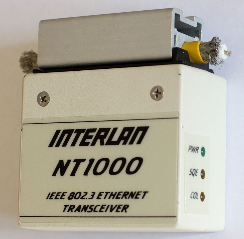
Network Technologies                                                                         Transmission Media

Physical Layer
       Functions of the Physical Layer
              Bit transmission on wired or wireless transmission paths
              Provides network technologies (e.g. Ethernet) and transmission media
              Frames from the Data Link Layer are encoded with line codes into signals

                                                                                                  Exercise sheet
                                                                                                  2 repeats the
                                                                                                  contents of
                                                                                                  this slide set
                                                                                                  which are
                                                                                                  relevant for
                                                                                                  these learning
                                                                                                  objectives
       Devices: Repeater, Hub (Multiport Repeater)
       Protocols: Ethernet, Token Ring, WLAN, Bluetooth,. . .
Prof. Dr. Christian Baun – 2nd Slide Set Computer Networks – Frankfurt University of Applied Sciences – WS2021    2/54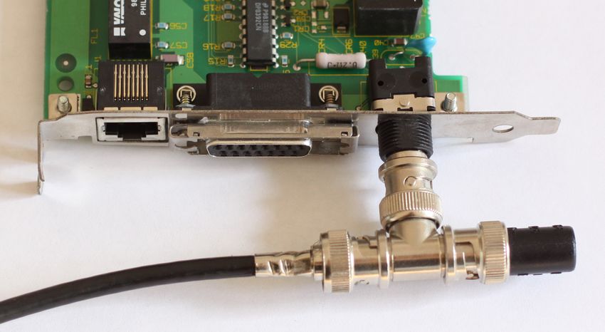
Network Technologies                                                                         Transmission Media

Learning Objectives of this Slide Set

       Physical Layer (part 1)
              Network technologies
                       Ethernet
                       Token Ring
                       Wireless LAN (WLAN)
                       Bluetooth
              Transmission Media
                       Coaxial cables
                       Twisted pair cables
                       Fiber-optic cables

Prof. Dr. Christian Baun – 2nd Slide Set Computer Networks – Frankfurt University of Applied Sciences – WS2021    3/54
Network Technologies                                                                         Transmission Media

Ethernet (IEEE 802.3)
       Developed in the 1970s by Robert Metcalfe and others at the Xerox
       Palo Alto Research Center
              Data rate of this first Ethernet version: 2,94 Mbps
       1983: IEEE standard since with 10 Mbps
       The most frequently used (cable-based) LAN technology since the
       1990s
              Ethernet displaced other standards (e.g. Token Ring) or made them niche
              products for special applications (e.g. FDDI)
       Several Ethernet standards exist
              They differ among others in the data rate and the transmission
              medium used
                       Versions for coaxial cables, twisted pair cables and fiber-optic cables, with
                       data rates up to 40 Gbit/s exist
       The connection type to the medium is passive
              This means that devices are only active when they send data
Prof. Dr. Christian Baun – 2nd Slide Set Computer Networks – Frankfurt University of Applied Sciences – WS2021    4/54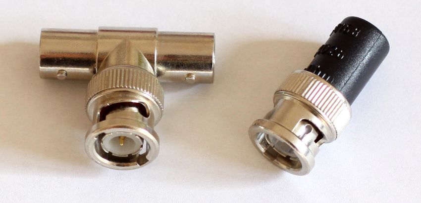
Network Technologies                                                                         Transmission Media

Some Variants of Ethernet

       All these variants are extensions of Thick Ethernet (10BASE5)
     Standard           Mbps      Transmission Medium
     10BASE2/5             10     Coaxial cables (50 ohm impedance)            Naming convention
     10BROAD36             10     Coaxial cables (75 ohm impedance)
     10BASE-F              10     Fiber-optic cables                                  Part 1: Data rate
     10BASE-T              10     Twisted pair cables
     100BASE-FX           100     Fiber-optic cables                                  Part 2: Transmission method
     100BASE-T4           100     Twisted pair cables (Cat 3)                         (baseband or broadband)
     100BASE-TX           100     Twisted pair cables (Cat 5)
     1000BASE-LX        1.000     Fiber-optic cables                                  Part 3: 100 times the
     1000BASE-SX        1.000     Fiber-optic cables (Multi-mode fiber)
     1000BASE-ZX        1.000     Fiber-optic cables (Single-mode fiber)
                                                                                      maximum segment length or
     1000BASE-T         1.000     Twisted pair cables (Cat 5)                         the transmission medium
     1000BASE-TX        1.000     Twisted pair cables (Cat 6)
     2.5GBASE-T         2.500     Twisted pair cables (Cat 5e)
     5GBASE-T           5.000     Twisted pair cables (Cat 6)                  10BASE5 for example means. . .
     10GBASE-SR        10.000     Fiber-optic cables (Multi-mode fiber)
     10GBASE-LR        10.000     Fiber-optic cables (Single-mode fiber)              Data rate: 10 Mbps
     10GBASE-T         10.000     Twisted pair cables (Cat 6A)
     40GBASE-T         40.000     Twisted pair cables (Cat 8.1)                       Transmission method:
                                                                                      Baseband
      2 different transmission modes exist:                                           Maximum segment length:
          1   Baseband (BASE)                                                         5 ∗ 100m = 500m
          2   Broadband (BROAD)
Prof. Dr. Christian Baun – 2nd Slide Set Computer Networks – Frankfurt University of Applied Sciences – WS2021    5/54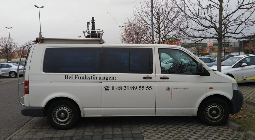
Network Technologies                                                                         Transmission Media

Variants of Ethernet – Baseband (BASE)

       Almost all Ethernet standards implement the baseband transmission
       method (BASE)
                Single exception: 10BROAD36
       Baseband systems have no carrier frequencies
                This means that data is directly (at baseband) transmitted on the
                transmission medium
       Digital signals are injected directly as impulses into the copper cable or
       fiber-optic and occupy the entire bandwidth of the cable or a part of it
                Unused bandwidth can not be used for other services
In short. . .
Baseband systems provide just a single channel

Prof. Dr. Christian Baun – 2nd Slide Set Computer Networks – Frankfurt University of Applied Sciences – WS2021    6/54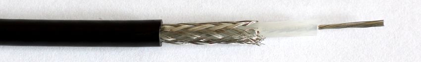
Network Technologies                                                                         Transmission Media

Variants of Ethernet – Broadband (BROAD)                                                                 Image Source: AVM

       The data is modulated to a carrier frequency
              This allows to transmit multiple signals at the same time in different
              frequency ranges (’bands’)
       Only 10BROAD36 uses the broadband method
              Because of high hardware costs for the modulation, the system was no
              economic success
      The broadband concept, used together with Ethernet,
      was no success, but the concept itself is used today in
      many areas of communication and telecommunication

Some fields of application of the broadband concept
      Via cable television, different TV channels, and with different
      carrier frequencies, also radio channels, telephone and internet is
      available
      The electrical power grid can be used to establish network
      connections (=⇒ Power line communication)
Prof. Dr. Christian Baun – 2nd Slide Set Computer Networks – Frankfurt University of Applied Sciences – WS2021        7/54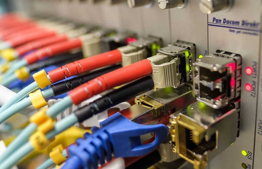
Network Technologies                                                                         Transmission Media

Token Ring (IEEE 802.5)

       Standard for LANs, in which the terminal devices are logically
       connected as a ring
       Data rate: 4 Mbps or 16 Mbps
       A token circles in the ring
              It is passed from one node to the next one
       The connection type to the medium is active
              This means the network stations participate actively in the token passing
       1981: Developed by the English company Procom
       From the mid-1980s: Further development by IBM
              1985: Introduced with 4 Mbps for the original IBM PC
              1989: 16 Mbps
              1998: 100 Mbps
       Until the mid-1990s: IBM’s preferred networking technology
              Obsolete, since IBM stopped the marketing and distribution in 2004
Prof. Dr. Christian Baun – 2nd Slide Set Computer Networks – Frankfurt University of Applied Sciences – WS2021    8/54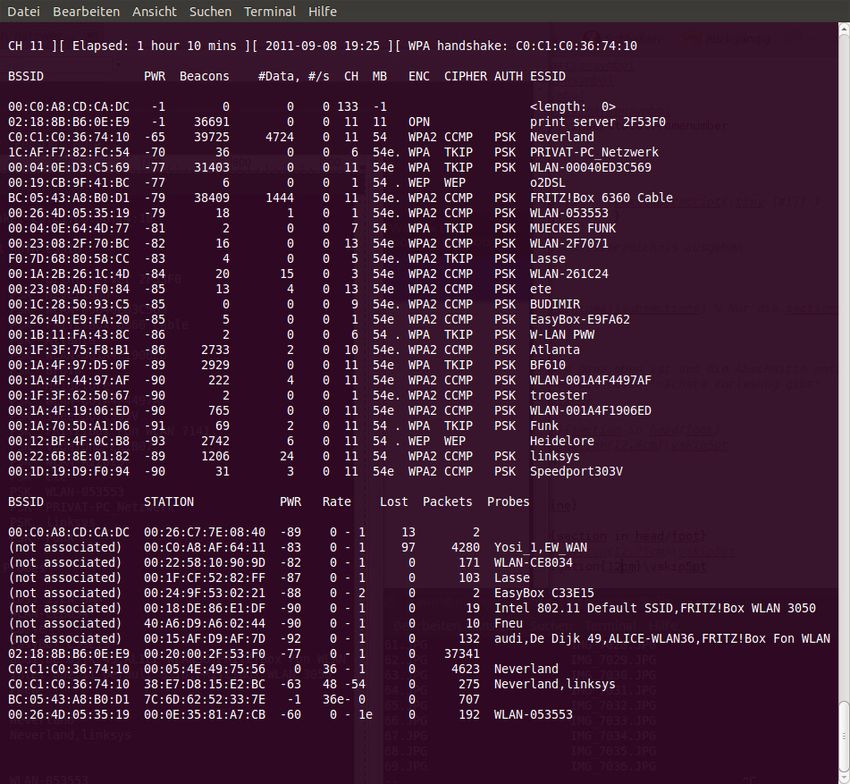
Network Technologies                                                                         Transmission Media

Functioning of Token Ring                                                 Image Source: Scott Adams (http://dilbert.com)

       The token frame is passed from one node to the next one
              If a terminal device wants to send data, it waits for the token frame
                       Then, the terminal device appends its payload at the token
                       It adds the required control signals to the token
                       It sets the token bit from value 0 (free token) to 1 (data frame)
              If a data frame token reaches its destination, the receiver copies the
              payload data and acknowledges the receive
                       The sender receives the acknowledgment and sends the token with the
                       next payload data or it puts a free token on the ring

Prof. Dr. Christian Baun – 2nd Slide Set Computer Networks – Frankfurt University of Applied Sciences – WS2021      9/54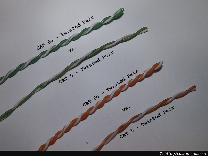
Network Technologies                                                                         Transmission Media

Challenges of Wireless Networks (1/2)
       WLAN = most popular technology for wireless computer networks
               The transmission medium has some special characteristics
                       These cause the following challenges

   1   Fading over distance (decreasing signal
       strength)
               Electromagnetic waves are gradually weakened
               by physical barriers (e.g. walls) and in free space
   2   Hidden terminal problem (invisible or hidden
       terminal devices)
               Terminal devices, communicating with the same
               device (e.g. an Access Point), do not recognize each
               other and therefore interfere with each other
                       Reason: Physical barriers

Source: Computernetzwerke, James F. Kurose, Keith W. Ross, Pearson (2008)

Prof. Dr. Christian Baun – 2nd Slide Set Computer Networks – Frankfurt University of Applied Sciences – WS2021    10/54
Network Technologies Transmission Media
Challenges of Wireless Networks (2/2)
3 Multipath propagation
Electromagnetic waves are reflected and
therefore go paths of different lengths from
the sender to the destination
Result: A difficult to interpret signal arrives
at the receiver because the reflections
influence subsequent transmissions
Similar problem: If objects move between
sender and receiver, the propagation paths
may change
4 Interferencing with other sources
Examples: WLAN and Bluetooth
Both network technologies operate on the same frequency band and
therefore can interfere
Also electromagnetic noise, caused by motors or microwave ovens can
cause interferences
Source: Computernetzwerke, James F. Kurose, Keith W. Ross, Pearson (2008)
Prof. Dr. Christian Baun – 2nd Slide Set Computer Networks – Frankfurt University of Applied Sciences – WS2021 11/54Network Technologies Transmission Media
Ad-hoc Mode and Infrastructure Mode
Communication between WLAN devices is possible in. . .
Ad-hoc mode: Terminal devices create a meshed network
The terminal devices communicate directly with each other
Each terminal device can have multiple connections to other
devices
To build up an ad-hoc network, the same network name –
Service Set Identifier (SSID) and the same encryption
parameters must be set on all terminal devices
Infrastructure mode: Each terminal device registers with
its MAC address at the Access Point
The Access Point sends at adjustable intervals (e.g. 10 times
per second) small beacon frames to all terminal devices in
range
The beacons contain among others the network name
(SSID), the list of supported data rates and the encryption
type
Prof. Dr. Christian Baun – 2nd Slide Set Computer Networks – Frankfurt University of Applied Sciences – WS2021 12/54Network Technologies Transmission Media
Data Rate of WLAN
IEEE Maximum (gross) Realistic (net)
The different WLAN Standard Data Rate Data Rate
standards provide 802.11 2 Mbps 1 Mbps
different data rates 802.11a 54 Mbps1 20-22 Mbps
802.11b 11 Mbps2 5-6 Mbps
All stations share 802.11g 54 Mbps 20-22 Mbps
the bandwidth for 802.11h 54 Mbps1 20-22 Mbps
upload and 802.11n 600 Mbps3 200-250 Mbps
802.11ac 1.733 Mbps4 800-850 Mbps
download 1 Some manufacturers added proprietary extensions
For this reason, to their products, enabling them to support 108 Mbps
the net at 40 MHz channel width
2 Some manufacturers added proprietary extensions
transmission rate to their products, enabling them to support 22 Mbps
is under optimal at 40 MHz channel width
3 When using 4x4 MIMO and 40 MHz channel width.
conditions little
more than the Several different configurations exist
4 When using 4x4 MIMO and 80 MHz channel width.
half gross rate Several different configurations exist
Prof. Dr. Christian Baun – 2nd Slide Set Computer Networks – Frankfurt University of Applied Sciences – WS2021 13/54Network Technologies Transmission Media
Transmission Power of WLAN Image Source: Google Image Search
WLAN is designed for use inside buildings
For this reason, it transmits with a relative low transmission power (up to
100 mW at 2.4 GHz and 1 W at 5 GHz)
Such transmission power levels are considered safe for health
For comparison, the transmission power of GSM phones, that operate in
the frequency range 880-960 MHz, is about 2 W
Some WLAN devices for 2.4 GHz provide a higher transmission power
Operating such devices is illegal in many countries =⇒ slide 15
Prof. Dr. Christian Baun – 2nd Slide Set Computer Networks – Frankfurt University of Applied Sciences – WS2021 14/54Network Technologies Transmission Media Measuring Vehicle of the Federal Network Agency Seen in Ludwigshafen-Oggersheim (November 26th, 2018) Prof. Dr. Christian Baun – 2nd Slide Set Computer Networks – Frankfurt University of Applied Sciences – WS2021 15/54
Network Technologies                                                                             Transmission Media

 WLAN Standards, Frequencies and Channels
        Most WLAN standards use the frequency blocks 2.4000-2.4835 GHz and
        5.150-5.725 GHz in the microwave range
                The standards differ among others in the frequency blocks used, data
                rates and modulation methods, as well as the resulting channel width
                                   IEEE             Standard                 Frequencies
                                   Standard           since             2.4 GHz    5 GHz
                                   802.11             1997                 X
                                   802.11a            1999                           X
                                   802.11b            1999                 X
                                   802.11g            2003                 X
                                   802.11h            2003                           X
                                   802.11n            2009                 X         X
                                   802.11ac           2013                           X

IEEE 802.11h is an adaptation of IEEE 802.11a to avoid disturbing military radar systems and satellite radio in Europe

Only differences to IEEE 802.11a: Additional skills dynamic frequency selection and transmission power control

Despite the fact that WLAN is used worldwide, legal differences exist

Example: In Germany, using 5.15-5.35 GHz is only allowed in enclosed rooms with 200 mW maximum transmission power

Prof. Dr. Christian Baun – 2nd Slide Set Computer Networks – Frankfurt University of Applied Sciences – WS2021           16/54
Network Technologies Transmission Media
Permitted use of WLAN in the 2.4 GHz Frequency Block
The frequency blocks are split into channels
Television and radio broadcasting follow the same principle
The frequency block 2.4 GHz is split into 13 channels
Bandwidth of each channel: 5 MHz
In Japan, an additional channel 14 can be used
Channel 14 is restricted for use only with the modulation method DSSS
Channel 14 is located 12 MHz above channel 13
Channel Frequency [GHz] EU USA Japan
1 2.412 X X X
2 2.417 X X X
3 2.422 X X X
4 2.427 X X X
5 2.432 X X X
6 2.437 X X X
7 2.442 X X X
8 2.447 X X X
9 2.452 X X X
10 2.457 X X X
11 2.462 X X X
12 2.467 X X X
13 2.472 X X X
14 2.484 X
Prof. Dr. Christian Baun – 2nd Slide Set Computer Networks – Frankfurt University of Applied Sciences – WS2021 17/54Network Technologies Transmission Media
Modulation Methods of the WLAN Standards
The different WLAN standards use different modulation methods
IEEE Standard Modulation Method Channel Width
802.11 FHSS1 or DSSS2 22 MHz
802.11a OFDM3 20 MHz
802.11b DSSS2 22 MHz
802.11g OFDM3 20 MHz
802.11h OFDM3 20 MHz
802.11n OFDM3 20 or 40 MHz
802.11ac OFDM3 20, 40, 80 or 160 MHz
1 Frequency Hopping Spread Spectrum
2 Direct Sequence Spread Spectrum
3 Orthogonal Frequency-Division Multiplexing
Why is the modulation method relevant?
It specifies the channel width
The width of the single channels specifies how many channels we can be used in the
permitted frequency ranges
Prof. Dr. Christian Baun – 2nd Slide Set Computer Networks – Frankfurt University of Applied Sciences – WS2021 18/54Network Technologies Transmission Media
Non-overlapping Channels of IEEE 802.11b
IEEE 802.11b uses the Direct Sequence Spread Spectrum (DSSS)
modulation scheme with 22 MHz wide channels and 5 MHz channel
spacing
Thus, only 3 (EU and U.S.) or 4 (Japan) channels exist, whose signals do
not overlap
Channel 1, 6, 11 and 14 (only in Japan)
DSSS distributes the payload over a wide frequency range
Therefore, it is almost insensitive to narrow-band interferences (e.g.
Bluetooth)
Prof. Dr. Christian Baun – 2nd Slide Set Computer Networks – Frankfurt University of Applied Sciences – WS2021 19/54Network Technologies Transmission Media
Non-overlapping Channels of 802.11g and 802.11n
IEEE 802.11g and 802.11n both use the Orthogonal Frequency-Division
Multiplexing (OFDM) modulation method
OFDM is a multi-carrier method
Each channel is 20 MHz wide and consists of 64 sub-carriers, which are
each 0.3125 MHz wide
Only 52 of the 64 sub-carriers are used
Thus, the effective bandwidth per channel is only 16.25 MHz
Therefore, only 4 non-overlapping channels exist: 1, 5, 9 and 13
802.11a devices also use the OFDM modulation method with 20 MHz wide channels. . .
but they operate exclusively in the frequency block 5.150-5.725 GHz
Prof. Dr. Christian Baun – 2nd Slide Set Computer Networks – Frankfurt University of Applied Sciences – WS2021 20/54Network Technologies Transmission Media
Non-overlapping Channels of IEEE 802.11n
802.11n also supports 40 MHz wide channels
If 40 MHz wide channels are used in the frequency block
2.4000-2.4835 GHz, only 2 channels exist (channels 3 and 11) whose
signals do not overlap
Each channel consists of 128 sub-carriers, which are each 0.3125 MHz
wide
Only 108 of the 128 sub-carriers are used
Thus, the effective bandwidth per channel is only 33.75 MHz
High quality terminal devices, which support 802.11n, can also use the frequency block
5.150-5.725 GHz
Prof. Dr. Christian Baun – 2nd Slide Set Computer Networks – Frankfurt University of Applied Sciences – WS2021 21/54Network Technologies Transmission Media
Non-overlapping Channels in the City Center. . .
are hard to find
Just have a look what is going on in
the neighborhood. . .
Request WLAN interface status:
# airmon-ng
Activate monitor mode of the interface:
# airmon-ng start
Check WLAN interface status again:
# airmon-ng
Collect WLAN frames:
# airodump-ng
Only for 2.4 GHz frequency block:
# airodump-ng –band bg
Only for 5 GHz frequency block:
# airodump-ng –band a
Prof. Dr. Christian Baun – 2nd Slide Set Computer Networks – Frankfurt University of Applied Sciences – WS2021 22/54Network Technologies Transmission Media
Channel Frequency EU USA Japan
36 5.180 GHz X1 X X1
40 5.200 GHz X1
X X1 Permitted use of WLAN in the 5
1
44 5.220 GHz X X X1
48 5.240 GHz X1
X X1 GHz Frequency Block
1,2,3
52 5.260 GHz X X2 X1,2,3
56 5.280 GHz X1,2,3
X2 X1,2,3
The higher the frequency, the
60 5.300 GHz X1,2,3 X2 X1,2,3 stronger is the attenuation caused by
64 5.320 GHz X1,2,3 X2 X1,2,3
100 5.500 GHz X2,3 X2 X2,3
the transmission medium
104 5.520 GHz X2,3 X2 X2,3 For this reason, WLAN at 2.4 GHz
108 5.540 GHz X2,3 X2 X2,3
112 5.560 GHz X2,3 X2 X2,3 reaches with the same transmission
116 5.580 GHz X2,3 X2 X2,3 power greater ranges than at 5 GHz
120 5.600 GHz X2,3 X2 X2,3
124 5.620 GHz X2,3 X2 X2,3
128 5.640 GHz X2,3 X2 X2,3
132 5.660 GHz X2,3 X2 X2,3
136 5.680 GHz X2,3 X2 X2,3
140 5.700 GHz X2,3 X2 X2,3
144 5.720 GHz X2,4 X2 —
149 5.745 GHz X2,4 X —
153 5.765 GHz X2,4 X —
157 5.785 GHz X2,4 X —
161 5.805 GHz X2,4 X —
165 5.825 GHz X2,4 X —
1
Indoor only
2
Dynamic Frequency Selection (DFS) Physical barriers cause with 5 GHz
3
Transmit Power Control (TPC)
4
Short Range Devices (SRD) = 25 mW max.
more problems than with 2.4 GHz
Prof. Dr. Christian Baun – 2nd Slide Set Computer Networks – Frankfurt University of Applied Sciences – WS2021 23/54Network Technologies Transmission Media
IEEE 802.11n – Multiple Input Multiple Output (MIMO)
The maximum gross data rate, when using IEEE
802.11n, depends on the number of antennas in the
stations and is 150, 300, 450 or 600 Mbps
The reason for this performance increase in
contrast to IEEE 802.11a/b/g/h, is because
802.11n implements MIMO Img. source: pixabay.com (CC0)
In addition to the extended channel width
(40 MHz), up to 4 antennas are used in MIMO
mode
They allow simultaneous working in the frequency
blocks 2.4 GHz and 5 GHz
Image source: pxhere.com (CC0)
With each parallel data stream (antenna), a
maximum data rate (gross) of 150 Mbps can be
achieved and up to 4 data streams can be bundled
The corresponding number of antennas (up to 4)
need to be equal on both sides
Image source: Christian Baun
Prof. Dr. Christian Baun – 2nd Slide Set Computer Networks – Frankfurt University of Applied Sciences – WS2021 24/54Network Technologies Transmission Media
IEEE 802.11ac
Also IEEE 802.11ac implements MIMO
8 parallel streams (antennas) are possible
Extended channel width (40 MHz, 80 MHz or
Img. source: Cookiemonster1979.
160 MHz) is possible Wikimedia (CC-BY-SA-4.0)
Operates only in the 5 GHz frequency block
Possible maximum (gross) data rate: 6.936 GBit/s
With 8*MIMO and 160 MHz channel width
Prof. Dr. Christian Baun – 2nd Slide Set Computer Networks – Frankfurt University of Applied Sciences – WS2021 25/54Network Technologies Transmission Media
WLAN Security – WEP
WLAN 802.11 implements the security standard Wired Equivalent
Privacy (WEP), which is based on the RC4 algorithm
Calculation of a XOR of the payload bit stream and the pseudo random
bit stream generated from the RC4 algorithm
Works with static keys that have a length of 40-bit or 104-bit
Can be cracked by known-plaintext attacks because the headers of the
802.11 protocol are predictable
The calculation of the WEP key with the help of a few minutes of
recorded data only takes a few seconds with tools such as Aircrack
WEP encryption of WLAN cracked in less than a minute
The Technical University of Darmstadt has managed another breakthrough in cracking WEP encrypted wireless networks. As Erik
Tews, Andrei Pychkine and Ralf-Philipp Weinmann described in a paper, they were able to reduce the amount of captured packets
which are required for a successful attack to less than a tenth. According to the researchers, a wireless network, secured with a
128-bit WEP key can be cracked with their attack in less than a minute. . .
News story from April 4th 2007. Source: http://heise.de/-164971
Prof. Dr. Christian Baun – 2nd Slide Set Computer Networks – Frankfurt University of Applied Sciences – WS2021 26/54Network Technologies Transmission Media
WLAN Security – WPA und WPA2
A better security standard is Wi-Fi Protected Access (WPA)
Bases on the RC4 algorithm too, but it offers increased security by using
dynamic keys
The dynamic keys base on the Temporal Key Integrity Protocol (TKIP)
The algorithm encrypts each data packet with a different key
Can be cracked by brute-force or via dictionary attacks on the password
Best security standard up to now: Wi-Fi Protected Access 2
(WPA2)
Bases on the Advanced Encryption Standard (AES)
In addition to TKIP, WPA2 includes the encryption protocol
Counter-Mode/CBC-Mac Protocol (CCMP)
CCMP is more secure than TKIP
A WLAN with WPA2 encryption, that is protected with a sufficiently
long password is currently considered secure
More information about RC4, AES,. . . =⇒ slide sets 11 + 12
Prof. Dr. Christian Baun – 2nd Slide Set Computer Networks – Frankfurt University of Applied Sciences – WS2021 27/54Network Technologies Transmission Media
Bluetooth
Wireless network system for short distance data transmission
It is designed to replace short cable connections between different devices
Development was initiated by the Swedish company Ericsson in 1994
Further development is done by the Bluetooth Special Interest Group
(BSIG)
Bluetooth is named after the Danish Viking King Harald Bluetooth
He was famous among other things for his communication skills
Bluetooth devices use the frequency block 2.402-2.480 GHz
WLANs, cordless phones and microwave ovens can cause interferences if
they operate in the same frequency band
To avoid interferences, Bluetooth uses a frequency hopping method, in
which the frequency band is divided into into 79 frequency stages at
intervals of 1 MHz
The frequency stages change up to 1600 times per second
Prof. Dr. Christian Baun – 2nd Slide Set Computer Networks – Frankfurt University of Applied Sciences – WS2021 28/54Network Technologies Transmission Media
Network Topologies of Bluetooth (1/2)
Bluetooth devices organize themselves in so-called piconets
A piconet consists of ≤ 255 nodes (≤ 8 are in active state)
The master can change the status of the other nodes
(activate/deactivate)
1 active node is the master
The remaining 7 active nodes are slaves
The master coordinates the media access
It assigns the transmission medium (the
air) to the nodes by providing
transmission slots to the slaves
This procedure is called: Time Division
Multiplexing
All nodes must share the bandwidth of the
network
Prof. Dr. Christian Baun – 2nd Slide Set Computer Networks – Frankfurt University of Applied Sciences – WS2021 29/54Network Technologies Transmission Media
Network Topologies of Bluetooth (2/2)
Each Bluetooth device can be registered in multiple Piconets
But it can only be the master of a single network
If a node in range of 2 Piconets, it can combine them to a Scatternet
Up to 10 Piconets form a Scatternet
Each Piconet is identified by the different alternations in the frequency
hopping method
The data rates of Scatternets are usually low
Prof. Dr. Christian Baun – 2nd Slide Set Computer Networks – Frankfurt University of Applied Sciences – WS2021 30/54Network Technologies Transmission Media
Versions of the Bluetooth Standards
Different versions of the Bluetooth standard exist
Latest version = version 4.0 =⇒ offers reduced power consumption
Maximum data rate:
Bluetooth up to version 1.2: 1 Mbps (721 kbit is payload)
Bluetooth 2.0: 3 Mbps (2.1 Mbps is payload)
Bluetooth 3.0 + HS (High Speed) uses WLAN to increase the data rate
A 3 Mbps Bluetooth connection is used for the transmission of the
control data and the session key
If 2 devices want to exchange large amounts of data, they switch into
high-speed mode and establish an ad-hoc connection via WLAN
802.11g with a data rate of 54 Mbps
=⇒ Bluetooth 3.0 + HS combines Bluetooth with WLAN
The possible (net) data rate is about 24 Mbps
Prof. Dr. Christian Baun – 2nd Slide Set Computer Networks – Frankfurt University of Applied Sciences – WS2021 31/54Network Technologies Transmission Media
Pairing of Bluetooth Devices
Before 2 Bluetooth devices can communicate with each other, they
need to know each other
Pairing = the process of getting to know each other
Before Bluetooth 2.1, pairing is complex
Both users need to enter an identical PIN
The PIN is the shared key for encryption and authentication
It ensures that no third device can listen to the connection or do a
man-in-the-middle attack
Bluetooth 2.1 introduced Secure Simple Pairing
This method uses the Diffie-Hellman algorithm (=⇒ slide set 12) for key
distribution instead of a PIN
The security of this pairing method depends on whether the terminal
devices are equipped with displays
If both devices have a display, each user needs to confirm a common code
by pressing a key
If a device lacks a display to show the code, the confirmation is impossible
Then a man-in-the-middle attack is still possible
Prof. Dr. Christian Baun – 2nd Slide Set Computer Networks – Frankfurt University of Applied Sciences – WS2021 32/54Network Technologies Transmission Media
Transmission Media
Different transmission media for computer networks exist
1 Cable-based transmission media
Copper cable: Data is transferred as electrical impulses via twisted pair
cables or coaxial cables
Fiber-optic cable: Data is transferred as light-impulses
2 Wireless transmission
Directed:
Radio technology: Data is transferred as electromagnetic waves (radio
waves) in the radio spectrum (e.g. WLAN and satellite internet access)
Infrared: Data is transferred as electromagnetic waves in the for the
human eye invisible infrared spectrum range (e.g. IrDA)
Laser: Data is transferred as light-impulses via Laser Bridge
Undirected:
Undirected wireless transmission is always based of radio technology (e.g.
mobile telephony, LTE, radio broadcasting and broadcasting via satellites)
Prof. Dr. Christian Baun – 2nd Slide Set Computer Networks – Frankfurt University of Applied Sciences – WS2021 33/54Network Technologies Transmission Media
Coaxial Cables (Coax Cables)
Bipolar cable with concentric (coaxial) structure
The inner conductor (core) carries the electrical signals
The outer conductor (shield) is kept at ground potential and
completely surrounds the inner conductor
The shielding of the signal-carrying conductor by the outer conductor
that is kept at ground potential, reduces electromagnetic interferences
Prof. Dr. Christian Baun – 2nd Slide Set Computer Networks – Frankfurt University of Applied Sciences – WS2021 34/54Network Technologies Transmission Media
Coaxial Cable for 10BASE5 – Thick Ethernet
10BASE5 (Yellow Cable or Thick Ethernet)
10 mm thick coaxial cable (RG-8) with
50 ohm impedance
For connecting terminal devices, a hole
must be drilled into the cable through
the outer shielding to contact the inner
conductor
Through the hole, the transceiver is
connected via a vampire tap with the
inner conductor
The terminal device is connected via a
transceiver cable (DB15), called AUI
(Attachment Unit Interface) with the
transceiver
Prof. Dr. Christian Baun – 2nd Slide Set Computer Networks – Frankfurt University of Applied Sciences – WS2021 35/54Network Technologies Transmission Media
Working Principle of Ethernet by Robert Metcalfe (1976)
With this drawing Robert Metcalfe demonstrated in June 1976 the
working principle of Ethernet on the National Computer Conference
Image source: Robert M. Metcalfe (1976)
Prof. Dr. Christian Baun – 2nd Slide Set Computer Networks – Frankfurt University of Applied Sciences – WS2021 36/54Network Technologies Transmission Media
Coaxial Cable for 10BASE2 – Thin Ethernet
The hardware required for Thick Ethernet is cost intensive
A less expensive solution is 10BASE2
It is called Thin Ethernet, ThinWire and sometimes Cheapernet
6 mm thick coaxial cable (RG-58) with 50 ohm impedance
The cables are thinner and more flexible, and therefore more simple to
install
Cables and devices have BNC connectors (Bayonet Neill Concelman)
T-Connectors are used to connect devices with the transmission medium
Terminators (50 ohm) are used to prevent reflections
Prof. Dr. Christian Baun – 2nd Slide Set Computer Networks – Frankfurt University of Applied Sciences – WS2021 37/54Network Technologies Transmission Media
Twisted Pair Cables (1/2)
The wires of twisted-pair cables are pairwise twisted with each other.
Twisted pairs are better protected against alternating magnetic fields
and electrostatic interferences from the outside than parallel signal wires
All variants of the Ethernet standard, that use twisted pair cables as
transmission medium, use plugs and jacks according to the standard
8P8C, which are usually called RJ45
Prof. Dr. Christian Baun – 2nd Slide Set Computer Networks – Frankfurt University of Applied Sciences – WS2021 38/54Network Technologies Transmission Media
Twisted Pair Cables (2/2)
Since the 1990s, twisted-pair cables and RJ45 plugs and jacks are
standard for copper-based IT networking
Ethernet 10BASE-T and Fast Ethernet
100BASE-TX both only use 2 pairs of
wires for sending and receiving
This allows using Ethernet Splitters
Image source: memegenerator.net
Why are 2 pairs of wires used for sending and receiving?
Fast Ethernet 100BASE-T4 and Gigabit
Ethernet 1000BASE-T both use all 4
See ‘Complementary Signal’ on slide 42
pairs of wires for sending and receiving
Prof. Dr. Christian Baun – 2nd Slide Set Computer Networks – Frankfurt University of Applied Sciences – WS2021 39/54Network Technologies Transmission Media
Wiring
T568A and T568B are standards for the pin assignment of the RJ45
plugs and jacks and are used for Fast Ethernet 100BASE-TX and
Gigabit Ethernet 1000BASE-T
Difference: The wire pairs 2 and 3 (green and orange) are interchanged
Mixing T568A and T568B in a computer network is a bad idea
This is T568B
When using 10BASE-T, 4 PINs are used – The remaining wire pairs are not used
TD+ and TD- (Trancieve Data) is the wire pair for data output signal
RD+ and RD- (Recieve data) is the wire pair for data input
Prof. Dr. Christian Baun – 2nd Slide Set Computer Networks – Frankfurt University of Applied Sciences – WS2021 40/54Network Technologies Transmission Media
Crossover Cables and Patch Cables
A Crossover cable can connect 2
terminal devices directly
It connects the send and receive lines
of both devices
To connect more than just 2 network
devices, patch cables are used
In this case, a Hub or a Switch is
required
Some Hubs and Switches provide an uplink port for
connecting another Hub or Switch
The uplink port is internally crossed
Auto-MDIX allows using crossover lines and patch cables any time
Modern network devices automatically detect the send and receive lines of connected
network devices
All network devices, which support Gigabit Ethernet 1000BASE-T or faster, implement
Auto-MDIX
Prof. Dr. Christian Baun – 2nd Slide Set Computer Networks – Frankfurt University of Applied Sciences – WS2021 41/54Network Technologies Transmission Media
Complementary Signal Source: Jörg Rech. Ethernet. Heise. 2008 and Wikipedia
Via the wire pair a complementary signal is sent (on one wire 0 V to
+2.8 V and on the other wire 0 V to -2.8 V)
This allows the receiver to filter out interfering signals
Furthermore, it reduces electromagnetic emission
The signal level of line
A=Payload Signal+Noise
The signal level of line
B= −Payload Signal+Noise
The difference of the signal levels of line A and line B at receiver side is:
[+Payload Signal+Noise] − [−Payload Signal+Noise] = 2∗Payload Signal
Result: Regardless of the level of the noise signal, the difference between the payload
signal and the complementary signal remains the same
Prof. Dr. Christian Baun – 2nd Slide Set Computer Networks – Frankfurt University of Applied Sciences – WS2021 42/54Network Technologies Transmission Media
Shielding of different Twisted Pair Cables
Twisted pair cables are often equipped with a metal shield to prevent
electromagnetic interferences
Label Meaning Cable shielding Pair shielding
UUTP Unshielded Twisted Pair none none
UFTP Foiled Twisted Pair none foil
USTP Shielded Twisted Pair none braiding
SUTP Screened Unshielded Twisted Pair braiding none
SFTP Screened Foiled Twisted Pair braiding foil
SSTP Screened Shielded Twisted Pair braiding braiding
FUTP Foiled Unshielded Twisted Pair foil none
FFTP Foiled Foiled Twisted Pair foil foil
FSTP Foiled Shielded Twisted Pair foil braiding
SFUTP Screened Foiled Unshielded Twisted Pair braiding and foil none
SFFTP Screened Foiled Foiled Twisted Pair braiding and foil foil
The label scheme follows the schema XXYZZ
XX is the cable shield
U = unshielded, F = foil shielding , S = braided shielding, SF = braided
shielding and foil
Y is the pair shielding
U = unshielded, F = foil shielding , S = braided shielding
ZZ stands for twisted pair (TP)
Prof. Dr. Christian Baun – 2nd Slide Set Computer Networks – Frankfurt University of Applied Sciences – WS2021 43/54Network Technologies Transmission Media Twisted Pair Cables – Examples Image Source: (Kabel): Wikipedia (CC0) Example 1: UTP Example 2: FUTP = FTP Example 3: SFTP Structure (SFTP) Prof. Dr. Christian Baun – 2nd Slide Set Computer Networks – Frankfurt University of Applied Sciences – WS2021 44/54
Network Technologies                                                                         Transmission Media

Shielded or Unshielded Cables?
       Shields must be electrically grounded on both sides of the cable
              If only one end of a shielded cable is grounded, an antenna effect occurs

                                                                                V
       This results in a compensation current (I =                              R)
              Compensating currents cause problems during operation or even the
              destruction of network devices
       For this reason, shielding can only be used if both sides of the cable
       have the same ground potential and therefore shielded cables cannot
       be used to connect different buildings
              Possible solutions are the installation of fiber-optic cables between
              buildings, laser bridges or wireless networks
Prof. Dr. Christian Baun – 2nd Slide Set Computer Networks – Frankfurt University of Applied Sciences – WS2021    45/54
Network Technologies Transmission Media
Categories of Twisted Pair Cables (1/3)
Different categories of twisted pair cables exist
The performance of a network connection is determined by the
component of the lowest category
Example: Devices, which support Cat6, are connected via a Cat5 cable
This reduces the performance of the connection to the values of Cat5
Category 1/2/3/4
Not common today (except for telephone cables)
Category 5/5e
Cat5e is guaranteed Gigabit Ethernet-compatible
It meets stricter test standards than Cat5 cables
Common in most current LANs
Category Max. frequency Compatible with. . .
Cat-5 100 MHz 100BASE-TX (100 Mbps, 2 wire pairs, 100 m)
1000BASE-T (1 Gbps, 4 wire pairs, 100 m)
Cat-5e 100 MHz 2.5GBASE-T (2.5 Gbps, 4 wire pairs, 100 m)
Prof. Dr. Christian Baun – 2nd Slide Set Computer Networks – Frankfurt University of Applied Sciences – WS2021 46/54Network Technologies Transmission Media
Categories of Twisted Pair Cables (2/3) Image Source: Reddit
Category 6/6A
Category Max. frequency Compatible with. . .
Cat-6 250 MHz 5GBASE-T (5 Gbps, 4 wire pairs, 100 m)
10GBASE-T (10 Gbps, 4 wire pairs, 55 m)
Cat-6A 500 MHz 10GBASE-T (10 Gbps, 4 wire pairs, 100 m)
Main differences (of the structure) between the categories: number of twists per wire length (cm) and thickness of the jacket
More twists per cm =⇒ less interference (noise)
Cat 5/5e has 1-2 twists per cm. Cat 6 has 2 or more twists per cm
Thickness of the cladding =⇒ less crosstalk
Crosstalk is the mutual interference of parallel lines
Prof. Dr. Christian Baun – 2nd Slide Set Computer Networks – Frankfurt University of Applied Sciences – WS2021 47/54Network Technologies Transmission Media
Categories of Twisted Pair Cables (3/3)
Category 7/7A
For Cat 7 and Cat 7A cables, other connectors (e.g., TERA or GG45)
and sockets than RJ45 were initially intended
However, these connectors were not successful in the market
Cat 7 and 7A cabling with RJ45 connectors offers no benefits over
category 6A cables
Category Max. frequency Compatible with. . .
Cat-7 600 MHz 10GBASE-T (10 Gbps, 4 wire pairs, 100 m)
Cat-7A 1000 MHz 10GBASE-T (10 Gbps, 4 wire pairs, 100 m)
Category 8.1
This standard supports cables of up to 30 m in length
Cables of this length are mostly sufficient for data centers
Category Max. frequency Compatible with. . .
Cat-8.1 2000 MHz 40GBASE-T (40 Gbps, 4 wire pairs, 30 m)
Prof. Dr. Christian Baun – 2nd Slide Set Computer Networks – Frankfurt University of Applied Sciences – WS2021 48/54Network Technologies Transmission Media
Information printed on Twisted Pair Cables (1/2)
Do you understand the most important cable characteristics that are printed on twisted pair cables?
Example: E188601 (UL) TYPE CM 75◦ C LL84201 CSA TYPE CMG FT4 CAT.5E PATCH CABLE TO
TIA/EIA 568A STP 26AWG STRANDED
PATCH/CROSS/CROSSOVER: see slide 41
UTP/STP/FTP/SFTP: see slides 43-44
CAT5/5E/6/7/8: see slides 46-48
24AWG/26AWG/28AWG: American wire gauge (AWG) informs about
the diameters of the wires
24AWG = 0.51054 mm, 26AWG = 0.405 mm, 28AWG = 0.321 mm
Larger wire diameter =⇒ less electrical resistance for the electronic
signals =⇒ lower attenuation
24AWG cables have lower attenuation than 26AWG or 28AWG cables
28AWG cables are thinner than 24AWG or 26AWG
Thinner cables block airflow in server racks less and simplify the
installation
Prof. Dr. Christian Baun – 2nd Slide Set Computer Networks – Frankfurt University of Applied Sciences – WS2021 49/54Network Technologies Transmission Media
Information printed on Twisted Pair Cables (2/2)
Do you understand the most important cable characteristics that are printed on twisted pair cables?
Example: E188601 (UL) TYPE CM 75◦ C LL84201 CSA TYPE CMG FT4 CAT.5E PATCH CABLE TO
TIA/EIA 568A STP 26AWG STRANDED
60◦ C/75◦ C: Temperature information stands for flame tests
SOLID/STRANDED
Solid cables use solid copper wires. Such cables are well suited for
permanent infrastructure installation. They have a lower attenuation and
cost less compared to stranded cables
Stranded cables consist of multiple strands of wires wrapped around
each other. They are typically used to create patch cables because they
are very flexible. Attenuation of stranded cables is higher compared to
solid cables. Thus, they are used for shorter distances.
Left image: Solid cable
Right image: Stranded
cable
Prof. Dr. Christian Baun – 2nd Slide Set Computer Networks – Frankfurt University of Applied Sciences – WS2021 50/54Network Technologies Transmission Media
Fiber-optic Cables Image Source: pixabay.com (CC0)
Often called optical fiber
Transfer data by using light
Light source: Normal LED or laser LED
Use wavelengths of 850, 1300 or 1550 nm
Propagation speed of the light in the glass: about
200,000 km/s
Advantages over coaxial and twisted pair cables
Provide high data rates over large distances
Create no electromagnetic emission
Insensitive against electromagnetic influences
Drawbacks:
Higher cost for cabling and active components (LEDs)
Existing twisted pair cable infrastructures can not be used
Used only when copper cables cannot provide enough bandwidth
Prof. Dr. Christian Baun – 2nd Slide Set Computer Networks – Frankfurt University of Applied Sciences – WS2021 51/54Network Technologies Transmission Media
Structure of Fiber-optic Cables Image Source (cable): pxhere.com (CC0)
Components of an optical fiber (from inside to outside):
1 Light-transmitting (core) made of quartz glass
2 The core is surrounded by a cladding layer
The refractive index of the core must be greater than that of the cladding
to enclose the optical signal
3 The core is surrounded by a coating layer that protects it from moisture
and physical damage
4 The final layer is the outer jacket to protect the inner layers
Prof. Dr. Christian Baun – 2nd Slide Set Computer Networks – Frankfurt University of Applied Sciences – WS2021 52/54Network Technologies Transmission Media
Multi-mode Fibers and Mono-mode (Single-mode) Fibers
.
Structure, dimensions and refractive index of core and cladding specify
the number of propagation modes, by which light can propagate
along the fiber
Each mode corresponds to one path in the optical fiber
Multi-mode Fibers provide up to
several thousand propagation
modes and mono-mode
(single-mode) fibers only a single
one
Short distance (≈< 500 m)
=⇒ multi-mode fibers
Long distance (≈< 70 km)
=⇒ mono-mode fibers
Prof. Dr. Christian Baun – 2nd Slide Set Computer Networks – Frankfurt University of Applied Sciences – WS2021 53/54Network Technologies Transmission Media
Types of Optical Fibers Image Source: Timwether. Wikipedia (CC-BY-SA-3.0)
Multi-mode fibers are classified
On step-index fibers, there is an
into step-index and abrupt refraction index change
graded-index between core and cladding
This reduces the output pulse
On graded-index fibers there is a
gradual change of the refraction
index between core and cladding
The output pulse is well
recognizable
The image demonstrates the reflection of light in a multi-mode
graded-index fiber
Prof. Dr. Christian Baun – 2nd Slide Set Computer Networks – Frankfurt University of Applied Sciences – WS2021 54/54You can also read