5G Small Cells and Cable - Realizing the Opportunity - NCTA Technical Papers
←
→
Page content transcription
If your browser does not render page correctly, please read the page content below
5G Small Cells and Cable

     Realizing the Opportunity

  A Technical Paper prepared for SCTE•ISBE by

                 Dave Morley
         Director, 5G and Regulatory
  Shaw Communications Inc. / Freedom Mobile
2728 Hopewell Place NE, Calgary, Alberta T1Y 7J7
               +1-403-538-5242
             dave.morley@sjrb.ca

 © 2018 SCTE•ISBE and NCTA. All rights reserved.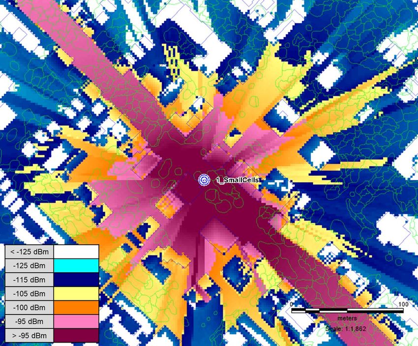
Table of Contents
Title                                                                                                                                  Page Number
Table of Contents .......................................................................................................................................... 2
Introduction.................................................................................................................................................... 4
5G Drivers ..................................................................................................................................................... 4
 1. Demand ............................................................................................................................................... 4
 2. Technology .......................................................................................................................................... 5
 3. Standards ............................................................................................................................................ 6
 4. Spectrum ............................................................................................................................................. 6
 5. Use Cases ........................................................................................................................................... 7
Network Densification and Small Cells ......................................................................................................... 9
 6. Challenges & Opportunities .............................................................................................................. 10
     6.1.   Site Acquisition ..................................................................................................................... 10
     6.2.   RF Coverage ........................................................................................................................ 12
     6.3.   Backhaul............................................................................................................................... 13
     6.4.   RAN Architectures ................................................................................................................ 14
     6.5.   Synchronization .................................................................................................................... 17
     6.6.   Converged Access Network ................................................................................................. 18
Conclusion................................................................................................................................................... 19
Abbreviations .............................................................................................................................................. 19
Bibliography & References.......................................................................................................................... 20

                                                                List of Figures
Title                                                                                                                                  Page Number
Figure 1 - Global Mobile Data Traffic (Source: Cisco Visual Networking Index 2017) ................................. 4
Figure 2 – Beamforming (Source: Nokia) ..................................................................................................... 5
Figure 3 - Network Slicing (Source: Nokia) ................................................................................................... 6
Figure 4 - 3GPP 5G Standards Roadmap (Source: 3GPP) .......................................................................... 6
Figure 5- Global 5G Spectrum Allocations (Source: Qualcomm) ................................................................. 7
Figure 6 - 5G Capabilities ............................................................................................................................. 8
Figure 7 - 5G Use Cases (Source: adapted from Nokia) .............................................................................. 8
Figure 8 - Network Densification ................................................................................................................... 9
Figure 9 - 5G Network Deployments by Spectrum Band ............................................................................ 10
Figure 10 - 4G Small Cell Deployments ...................................................................................................... 10
Figure 11 - Strand-Mount 4G Small Cell Deployments ............................................................................... 11
Figure 12 - Typical Strand-mount Small Cell Installation ............................................................................ 12
Figure 13 – Outdoor small cell coverage predictions for LTE @ 2500 MHz (left) and 5G NR @ 3500
     MHz (right) ........................................................................................................................................... 13
Figure 14 - Possible 5G NR Functional Splits (Souce: adapted from Nokia) ............................................. 14
Figure 15 - CPRI Line Rates ....................................................................................................................... 16
Figure 16 - Evolution of DOCSIS Aggregate Line Rates ............................................................................ 16
Figure 17 - LTE Carrier Frequency Error on a production DOCSIS network ............................................. 18

                                               © 2018 SCTE•ISBE and NCTA. All rights reserved.                                                                  2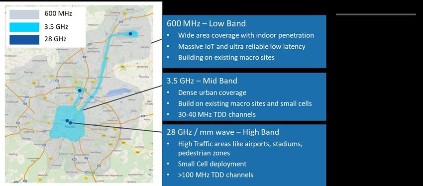
Figure 18 - Converged DAA/5G Access Network ....................................................................................... 18

                                                      List of Tables
Title                                                                                                          Page Number
Table 1 - 4G & 5G Small Cell Synchronization Requirements ................................................................... 17

                                      © 2018 SCTE•ISBE and NCTA. All rights reserved.                                               3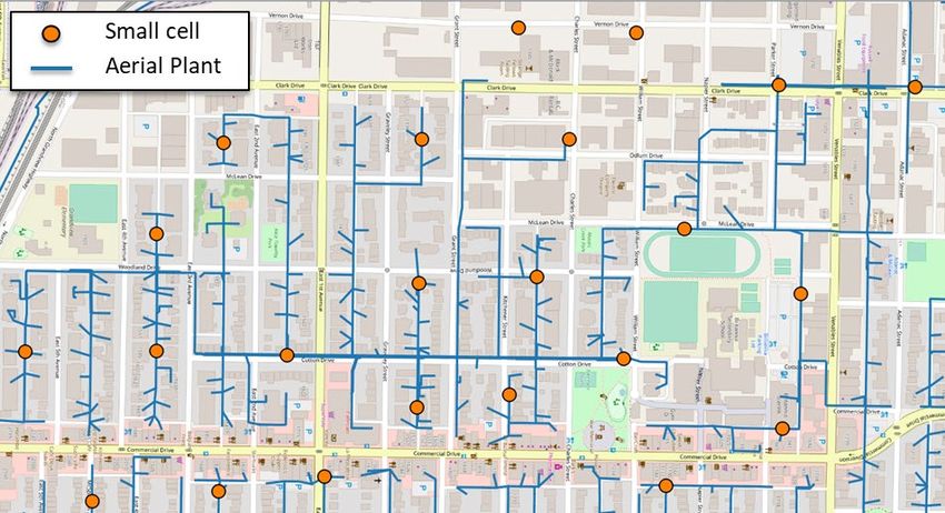
Introduction
As wireless networks evolve from 4G/LTE to 5G, small cells will play a critical role in delivering the
high bandwidth, low-latency connections required by the myriad potential 5G use cases. With regulators
opening up new low, mid and high-band millimeter wave (mmWave) spectrum for 5G, MSOs are
uniquely positioned to create ultra-dense 5G wireless networks by leveraging their existing hybrid fiber
coax (HFC) networks and emerging technologies such as full duplex DOCSIS (FDX) and distributed
access architectures (DAA). This paper examines the drivers for the adoption of 5G and the potential
opportunities and challenges presented by 5G small cells based on insights from Shaw Communications’
recent deployments of 4G/LTE small cells, through its subsidiary Freedom Mobile.

                                         5G Drivers
5G promises to dramatically transform the role that mobile technology plays in the world, creating new
economic opportunities and promoting social development. By 2020, 5G is expected to add $1 trillion to
the economy of North America alone [1]. It will also impact all aspects of our society from facilitating
smart-city energy grids and the Internet of things (IoT) to enabling autonomous vehicles and remote
healthcare. The key drivers behind the shift to 5G include growing global demand for wireless services,
ongoing advancement of wireless technologies, emergence of new use cases, development of global
standards and the availability of new spectrum bands for 5G. These drivers are explained in more detail
in the following subsections.

1. Demand
Global demand for mobile data continues to grow unabated as subscribers increasingly consume and
share video content. In addition, as mobile devices become even more capable with added processing
power, higher-resolution screens, and advanced features such as gesture-based interfaces, consumers are
demanding faster, more reliable mobile connectivity.

    Figure 1 - Global Mobile Data Traffic (Source: Cisco Visual Networking Index 2017)

As shown in Figure 1, the Cisco Visual Networking Index (VNI) predicts that global mobile data traffic
will increase 7-fold between 2016 and 2021, representing a cumulative average growth rate (CAGR) of

                              © 2018 SCTE•ISBE and NCTA. All rights reserved.                              4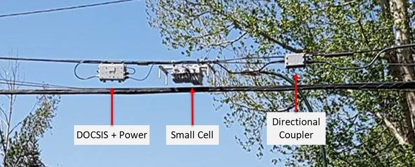
47% [2]. Cisco also forecasts that average mobile connection traffic per month will grow by over 5 times
during the same period, from 1 GB in 2016 to 5.4 GB in 2021. The same study predicts that the number
of mobile-connected devices per capita will reach 1.5 by 2021.

2. Technology
Another important driver for the adoption of 5G is the rapid evolution of wireless technology. Two key
developments are massive multi-input multi-output (MIMO) systems and beamforming antennas, which
together offer improved network coverage and traffic capacity. As shown in Figure 2, beamforming
creates highly-focused beams from the base station to individual users. This counteracts propagation
losses, particularly at mmWave frequencies and minimizes interference from other sources, both of which
allow higher data rates to be supported than would otherwise be the case.

                            Figure 2 – Beamforming (Source: Nokia)

Massive MIMO in turn uses multiple antennas to simultaneously serve many users by exploiting multiple
radio paths to increase system capacity.

Another key technology driving 5G is advanced channel coding techniques, which provide more efficient
and robust data transmission compared with previous coding methods, supporting larger data blocks and
more reliable control channels. A scalable OFDMA air interface has also been developed that efficiently
addresses different spectrum, deployment and service scenarios by adopting a flexible subcarrier spacing
and slot structure.

The 5G core network is also evolving to fully embrace network function virtualization (NFV) and
software defined networking (SDN), which together will enable faster, more agile and scalable networks.
As shown in Figure 3 below, network slicing will also allow core networks to be dynamically configured
on a per vertical or per service basis.

                              © 2018 SCTE•ISBE and NCTA. All rights reserved.                          5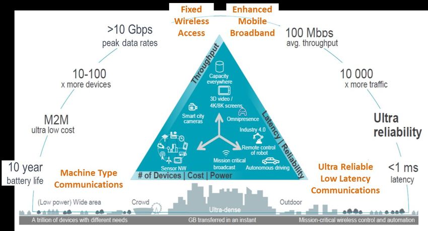
Figure 3 - Network Slicing (Source: Nokia)

3. Standards
5G standards are also proceeding rapidly with the recent finalization of 3GPP Release 15 in June 2018.
This release defines the 5G new radio (NR) standards for both non-standalone (NSA) and standalone
(SA) operation. NSA operation allows inter-working with the existing 4G evolved packet core (EPC),
while standalone (SA) operation if for the new 5G core network (CN). As shown in the figure below, the
5G CN standards are expected to be completed in Release 16 in the 1st half of 2019.

                   Figure 4 - 3GPP 5G Standards Roadmap (Source: 3GPP)

4. Spectrum
The allocation of low, mid and high band (mmWave) spectrum for 5G is also well underway or
completed in several countries around the globe, including the U.S., Canada, Japan, China Korea, and
European countries (see Figure 5).

                              © 2018 SCTE•ISBE and NCTA. All rights reserved.                          6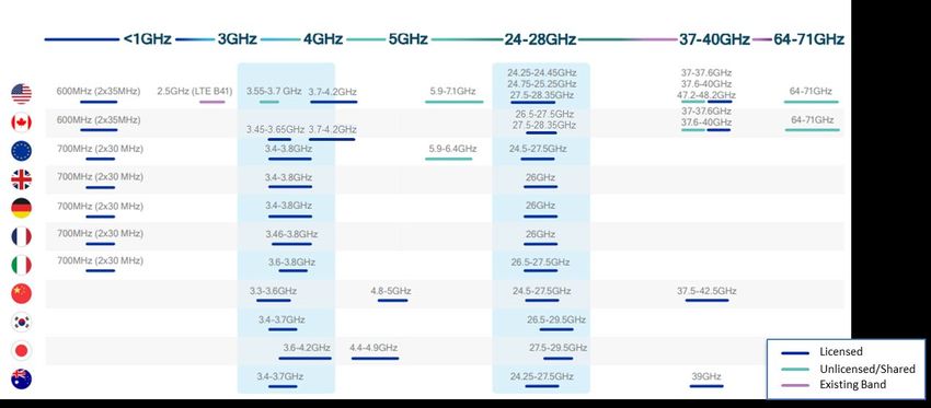
Figure 5- Global 5G Spectrum Allocations (Source: Qualcomm)

In the U.S. and Canada, the initial bands designated for 5G include the 600 MHz, 3500 MHz and 24-28
GHz bands. Additional spectrum bands under consideration include the 3.7-4.2 GHz, 37-40 GHz and 64-
71 GHz bands. The use of high-frequency mmWave spectrum bands above 24 GHz is emerging as a key
5G enabler. The use of these bands is very compelling because of the large bandwidths available at
mmWave frequencies, enabling extremely high data rates and significant increases in capacity.

5. Use Cases
The key technologies noted above coupled with supporting standards and spectrum, create a range of
fundamental new capabilities illustrated in Figure 6. As defined in IMT-2020 [3], these capabilities
include 10x higher data rates, 10x lower latency, and 10x higher network efficiency than previous 4G
networks.

                              © 2018 SCTE•ISBE and NCTA. All rights reserved.                          7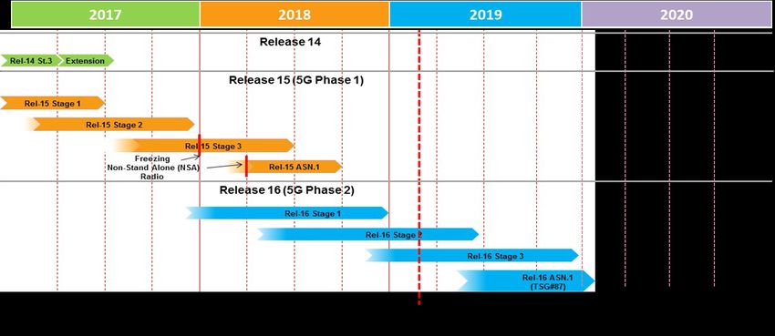
Figure 6 - 5G Capabilities

Given these new capabilities, 5G is expected to support myriad use cases, some of which haven’t even
been envisaged yet. Those that have can be grouped into 4 main categories: fixed wireless access (FWA),
enhanced mobile broadband (eMBB), machine type communications (mTC), and ultra-reliable low
latency communications (uRLLC), as shown in Figure 7.

                    Figure 7 - 5G Use Cases (Source: adapted from Nokia)

FWA promises to deliver multi-gigabit speeds to fixed residential and business premises using mmWave
spectrum. As such, FWA is an alternative to wired broadband services and represents a potential threat to
traditional wireline providers including MSOs. At the same time, FWA also provides MSOs with the
opportunity to deliver broadband services in “brown-field” areas that are not currently served by the

                              © 2018 SCTE•ISBE and NCTA. All rights reserved.                           8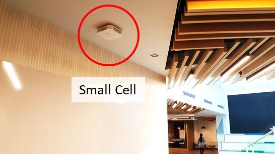
operator such as new residential markets and industrial/business parks. FWA can also be used to provide
critical small cell backhaul in areas without existing wireline infrastructure.

eMBB, with its multi-gigabit per second speeds and inherent mobility, will support new immersive
experiences such as virtual and augmented Reality (VR/AR), high resolution video, and “flash
download/upload” uses cases such as software updates and video downloads. eMBB will also be used to
support highly congested environments such as stadiums and airports.

At the other end of the scale, mTC will require much lower throughputs but will need to support billions
of devices, often with very low energy consumption requirements. mTC has numerous applications in
sensor networks, smart cities, agriculture, retail, logistics, and a plethora of other use cases in a world of
increasing connected things.

uRLLC encompasses mission critical real-time applications such as industrial control, remote robotics,
remote surgery/health and autonomous driving.

            Network Densification and Small Cells
While 5G opens up a world of new use cases, it also comes with a number of important implications.
One that represents both a challenge and an opportunity, particularly for MSOs, is network densification.
That is, to realize the higher data rates and area traffic capacities promised by 5G, operators will need to
deploy much denser network topologies using small cells. Figure 8 illustrates the transition that needs to
be made from today’s networks, which are larger composed of macro cells, to 5G networks of the future
with the targeted deployment of small cells.

                                   Figure 8 - Network Densification

For eMBB applications, for example, small cells will likely be deployed in both mid-band and mmWave
bands depending on the type of environment. As shown in Figure 9, mid-band (e.g., 3.5 GHz) small cells
are best suited for dense urban areas, whereas mmWave (e.g., 28 GHz) small cells will typically be
deployed in extremely high traffic areas such as stadiums, airports and pedestrian zones. In addition,
mmWave small cells may also be deployed for FWA or flexible use deployments, serving both fixed and
mobile subscribers. In contrast, 600 MHz will most likely be deployed at macro sites to provide wide
area and in-building coverage.

                                © 2018 SCTE•ISBE and NCTA. All rights reserved.                                  9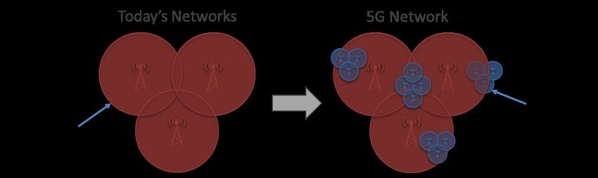
Figure 9 - 5G Network Deployments by Spectrum Band

6. Challenges & Opportunities
The main challenges associated with deploying 4G/5G small cells include site acquisition, backhaul,
synchronization and powering.

    6.1. Site Acquisition
Certainly, one opportunity for the cable industry is to leverage their existing Wi-Fi hotspot and/or 4G
small cell locations to deploy 5G small cells. With access rights to millions of public Wi-Fi hotspots,
often in prime “beach front” properties, the cable industry is uniquely positioned to capitalize on this
opportunity, either as a wireless player or a wholesale provider to existing MNOs.

At Freedom Mobile this strategy is currently being used to deploy 4G/LTE-A small cells. Figure 10
shows an indoor small cell that was installed at an existing Wi-Fi hotspot (left) and a new outdoor small
cell at a transit station (right). In the future, both locations will be used for the deployment of 5G small
cells.

                               Figure 10 - 4G Small Cell Deployments

                                © 2018 SCTE•ISBE and NCTA. All rights reserved.                            10
In addition, MSOs can leverage their existing cable infrastructure, and in particular aerial plant, to quickly
deploy small cells in targeted areas. Deploying small cells on aerial plant addresses three key challenges
with small cell deployments: site access, backhaul and power. That is, access is usually already covered
by existing pole-line attachment agreements and both backhaul and power are available on the coaxial
cable plant.
Figure 11 shows one such deployment in a major metro area by Freedom Mobile. In this case, strand-
mount 4G/LTE-A small cells are being installed on aerial strand with inter-site distances ranging from
175 to 225 meters.
Figure 11 - Strand-Mount 4G Small Cell Deployments
Figure 12 shows a typical strand-mount small cell installation, which consists of a small cell gateway, an
4G/LTE-A small cell and directional coupler. The small cell gateway contains a DOCSIS 3.1 cable
© 2018 SCTE•ISBE and NCTA. All rights reserved. 11modem and power supply, which converts 90 VAC quasi-square wave input power (i.e., Power-over-
Cable) to 115 VAC output power for the small cell.
Figure 12 - Typical Strand-mount Small Cell Installation
The 4G/LTE-A small cell can be equipped with up to 3 radio frequency (RF) modules, each capable of
supporting 2 x 2 MIMO with up to 2 x 5W transmit power. For dense pedestrian zones, the small cell is
typically equipped with a license-assisted access (LAA) RF module, which operates in the 5 GHz
unlicensed band. In this configuration, the small cell supports a peak data rate of up to 450 Mbps using
two 20 MHz carriers in the unlicensed band and one 15 MHz carrier in the licensed AWS-3 band. The
directional coupler connects the small cell gateway to the hybrid fiber-coaxial (HFC) cable plant, which
provides both the power and connectivity for the DOCSIS backhaul circuit. At the cable modem
termination system (CMTS), the small cell backhaul circuit is routed to the LTE evolved packet core
(EPC) network.
As mentioned, a key advantage of using the HFC cable plant for small cell deployments is the availability
of power in addition to backhaul connectivity. As a result, small cells can be deployed quickly and easily
wherever the MSO has existing coaxial plant. In contrast, passive optical networks (PONs), for example,
require a separate power service to be installed, which adds to the cost, time and complexity of the
installation.
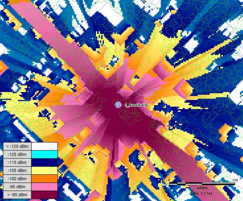
6.2. RF Coverage
A key consideration in 5G small cell deployments is meeting radio frequency (RF) coverage
requirements. Although inter-site distances for the outdoor small cell deployments in Figure 11 were
designed for LTE at 2500 MHz band, comparable coverage can be achieved with 5G NR at 3500 MHz.
Figure 13 shows RF coverage predictions for LTE at 2500 MHz and 5G NR at 3500 MHz using
Infovista’s Planet 7 RF network planning tool. This figure shows that the coverage is virtually identical
for both bands.
Simulation studies of 5G NR mmWave network coverage by Qualcomm also show that significant
coverage is possible when co-locating mmWave equipment with existing 4G macro and small cell sites
[4]. Of the 15 cities studied, the outdoor downlink coverage at 28 GHz varied from 50% to 80% of the
existing 4G network coverage in 9 of the 15 cities studied. These results suggest that deploying mmWave
small cells in urban areas using existing 4G cell sites is entirely feasible, especially in areas with high-
© 2018 SCTE•ISBE and NCTA. All rights reserved. 12density deployments. While outdoor-to-indoor coverage is not feasible in the mmWave band due to much
higher material attenuation (e.g., low-e glass), providing outdoor mmWave coverage would free-up
significant capacity in the sub-6 GHz band for outdoor-to-indoor capacity.
Figure 13 – Outdoor small cell coverage predictions for LTE @ 2500 MHz (left) and 5G NR
@ 3500 MHz (right)
For indoors locations, we expect that 5G NR coverage at 3500 MHz to be virtually identical to LTE at
2500 MHz as well. Qualcomm also conducted indoor network coverage simulations at mmWave
frequencies with similar results. A simulation study was done for the Las Vegas Convention Center using
existing 4G antenna locations in the venue. A one-to-one overlay of 5G mmWave radios on the existing
4G/LTE antenna locations resulted in significant coverage (up to 85%) throughout the facility.
In buildings with existing Wi-Fi access points, the above results suggest that coverage parity might be
achieved with a one-to-one mmWave small cell overlay since inter-access point distances for Wi-Fi
access points are typically much shorter than 4G small cells. Replacing existing Wi-Fi access points
and/or 4G small cells with 5G equipment could result in substantial cost and time savings for 5G
deployments.
6.3. Backhaul
As noted earlier, another substantial challenge in deploying small cells is securing the necessary backhaul
connectivity (or transport) from the small cell to the core network. There are multiple transport solutions
available today, including dedicated fiber, wavelength division multiplexing (WDM), passive optical
networks (PON), DOCSIS and microwave radio. The preferred solution is dependent on a variety of
factors and considerations, including technical performance, immediacy of deployment, capacity, cost,
and accessibility.
Historically, Freedom Mobile has relied primarily on dedicated fiber and microwave for macro cell
backhaul. With the introduction of 4G small cells, however, DOCSIS 3.1 is now being successfully used
to backhaul traffic from both indoor and outdoor small cells in locations that fall within Shaw’s cable
footprint.
When deployed in areas with a mid-split 1 GHz HFC plant, these cable modems are provisioned for
maximum downlink (DL) and uplink (UL) data rates of 500 Mbps and 100 Mbps, respectively. These
© 2018 SCTE•ISBE and NCTA. All rights reserved. 13maximum data rates coincide with the peak data rates of the 4G small cells currently being deployed.
However, since the peak data rates can only be achieved under ideal conditions, the average the DL/UL
data rates during the busy hour are much lower, typically 20-25% of the peak rates. Therefore, up to 5
small cells can usually be served by a single cable modem.
The main advantages of DOCSIS compared with the other alternatives are its low cost, scalability, access
to power, and ease of deployment. Another key advantage of DOCSIS is availability. Within Shaw’s
HFC network, for example, there is typically 3 to 5 times more coaxial cable than fiber in major metros
markets. Over time this ratio will certainly decrease but in the short-to-medium term there is a huge
incentive leverage DOCSIS for 5G small cell densification.
With its higher peak data rates and lower latencies, however, 5G introduces a new set of demands on the
backhaul/ transport facilities, which are discussed in further detail in the sections below.
6.4. RAN Architectures
For 5G NR small cells, the transport requirements depend on several factors including: the total channel
bandwidth; the number of MIMO Layers; the maximum supported modulation scheme; and the number
of transmit and receive antennas. The division of radio functions between the remote radio sites and
centralized locations also plays an important role in the transport requirements. These radio functions
include RF signal processing, baseband (or Layer 1) signal processing, and other networking layers (i.e.,
Layer 2 & 3) in the end-to-end protocol stack.
Figure 14 - Possible 5G NR Functional Splits (Souce: adapted from Nokia)
As illustrated in Figure 14, there are several possible options for splitting these functions between the
radio site and a central location such as a hub site. The upper portion of this figure shows the functions
residing at the radio site whereas the lower portion shows the functions at a central site. The throughput
and latency requirements are shown over the links between the two.
© 2018 SCTE•ISBE and NCTA. All rights reserved. 14The first option on the left-hand side (Option 1) represents a conventional base station (BTS) where all
functions are implemented at the radio site. The transport facility in the case is referred to as “backhaul”.
The advantage of this option is the throughput and latency are minimized because all processing is done
at the radio site. In the 5G NR standard, the interface between the BTS and core network is known as the
‘NG’ interface [5]. The backhaul options for the NG interface include dedicated fiber, WDM, DOCSIS
and PON.
Option 4 at the other end of the scale represents the conventional remote radio head (RRH) architecture,
sometimes referred to a centralized radio access network (C-RAN) or virtualized radio access network
(vRAN), if the functions run on virtualized platforms. The RRH performs the RF signal processing only
and leaves all other functions to be performed in a baseband unit (BBU) at a central site. With C-RAN,
the transport is referred to as “fronthaul” and typically uses the common public radio interface (CPRI) to
transport digitized IQ samples of the baseband signal over fiber or WDM from the radio site to the BBU.
The advantages of this approach include simpler radio equipment at the network edge, easier operation,
and cheaper maintenance. C-RAN also allows BBU processing capacity to be efficiently reused or shared
as demand patterns shift over time. This is particularly relevant for high-density 5G deployments such as
stadiums where peak and off-peak demand vary dramatically. The challenge with C-RAN deployments is
it requires the RRH and BBU to be connected through a high-speed, low-latency, and accurately
synchronized network. Figure 15 shows the required CPRI line rate (without coding) for various channel
bandwidths and numbers of transmit/receive antennas. This figure clearly shows that with the higher
channel bandwidths and transmit/receive antenna counts associated with 5G, it quickly becomes
impractical to use CPRI for 5G fronthaul [6].
With the above in mind, the industry partners responsible for the CPRI specification have developed a
new fronthaul specification known as evolved CPRI (eCPRI) [7]. eCPRI offers a ten-fold reduction in the
required data rate and allows packet-based transport technologies such as Ethernet to be used. This is
Option 3 above.
The final option (Option 2) is based on the F1 interface defined in the 5G NR standard, which assigns the
RF, Layer 1 and low-level Layer 2 functions to the radio sites and the other functions in the central site.
The advantage of this split is it retains some of the benefits of lower layer splits, while minimizing the
throughput and latency requirements.
© 2018 SCTE•ISBE and NCTA. All rights reserved. 15Figure 15 - CPRI Line Rates
With the continued evolution of DOCSIS standards, we believe that DOCSIS is a viable transport
technology for 5G small cells. While the required line rates for eCPRI of up to 100 Gbps are too high for
DOCSIS technology, small cells that implement the F1 or NG interfaces could conceivably be carried
over DOCSIS. As shown in Figure 16 below, the projected DOCSIS line rates for full duplex DOCSIS
(FDX) and extended spectrum DOCSIS, are well within range of those required for the F1 and NG
interfaces.
Figure 16 - Evolution of DOCSIS Aggregate Line Rates
Although latency on typical DOCSIS networks currently exceeds the requirements for the F1 interface
(i.e., < 5 ms), work by Andreoli-Fang and Chapman [8] demonstrates that latencies of 1-2 ms can be
achieved using upstream grant pipelining techniques between LTE/5G and DOCSIS.
© 2018 SCTE•ISBE and NCTA. All rights reserved. 166.5. Synchronization
Another important consideration for small cell deployments is synchronization. Unlike Wi-Fi access
points, 4G and 5G small cells require precise synchronization to minimize inter-site interference. The
minimum frequency and phase requirements for 4G and 5G small cells are listed in Table 1 below.
Table 1 - 4G & 5G Small Cell Synchronization Requirements
Parameter 4G1 5G
Frequency +/- 50 ppb +/- 50 ppb
Phase N/R < 1.5 µs
1. Assumes FDD mode with no advanced features enabled such as CoMP, eICIC, etc.
In Freedom Mobile’s current mobile network, 4G small cells are synchronized via either GPS or precision
time protocol (PTP), also known as IEEE 1588v2. GPS/GNSS is currently used for outdoor small cells
and PTP is used for indoor small cells. In cases where the outdoor small cell does not have line of sight
to a sufficient number of GPS/GNSS satellites, PTP can be used for synchronization as well. Since none
of Freedom’s 4G small cell operate in TDD mode or use advance features (e.g., coordinated multipoint
(CoMP), enhanced inter-cell interference coordination (eICIC)), phase synchronization is not required.
For indoor small cells, PTP is distributed from centrally located grandmaster clocks in each metro area to
the small cells over the transport network. This eliminates the need to deploy a local grand master clock
on site or install external GPS/GNSS antennas and coaxial cabling for each small cell, both of which
would introduce significant deployment costs and time delays.
For indoor sites with fiber backhaul, PTP can be used to reliably distribute both frequency and phase
synchronization. For sites with DOCSIS backhaul, however, PTP can only be used to distribute
frequency synchronization due to the asymmetric latency between the DOCSIS downlink and uplink and
the lack of support for PTP in existing DOCSIS implementations .
During initial small cell deployments there were doubts whether frequency synchronization could be
distributed transparently over DOCSIS using PTP. Through extensive testing, however, Shaw has
validated that the frequency error meets the 3GPP specification of +/- 50 ppb limit. Figure 17 shows
actual frequency error test results from a 4G small cell on a production DOCSIS network. These results
show that the frequency is well within specification. To the best of our knowledge, this is the first time
that frequency synchronization has been distributed to 4G small cells over a DOCSIS network using PTP.
© 2018 SCTE•ISBE and NCTA. All rights reserved. 17Figure 17 - LTE Carrier Frequency Error on a production DOCSIS network
For 5G small cells, however, the lack of support for phase synchronization over DOCSIS is a serious
shortcoming. Fortunately, the DOCSIS timing protocol (DTP), which is part of the DOCSIS 3.1
specification, and allows phase and time synchronization to be accurately distributed over DOCSIS [9].
Further work is required, however, by DOCSIS chipset, CMTS and cable modem vendors to fully
implement DTP before 5G small cell deployments begin, likely in late 2019 or early 2020.
6.6. Converged Access Network
In addition to leveraging DOCSIS for small cell backhaul, MSOs could also take advantage of obvious
synergies between 5G small cells and distributed access architectures (DAA) and fiber deeper initiatives.
For example, as shown in Figure 18 below, wavelength division multiplexing could be used to aggregate
traffic from both DAA nodes and 5G NR macro and small cell sites.
Figure 18 - Converged DAA/5G Access Network
© 2018 SCTE•ISBE and NCTA. All rights reserved. 18This would allow eCPRI, for example, to be used for high-density 5G NR sites (i.e., both macro and small
cells) where peak data rates exceed DOCSIS capacities. Of course, this would not preclude using
DOCSIS for backhaul at lower density sites, as required.
Conclusion
5G promises to dramatically transform the role that mobile technology plays in the world. By leveraging
their existing and planned network assets, MSOs are well-positioned to capitalize on emerging 5G
opportunities, either as mobile network operators or wholesale providers. As wireless networks evolve
from 4G/LTE to 5G, small cells will be a key component for delivering the high bandwidth, low-latency
connections required by the broad range of use cases 5G makes possible. With hundreds of thousands of
Wi-Fi hotpots around the globe and existing support structure agreements, MSOs should have ready
access to prime real estate for small cell deployments. This paper also shows that current DOCSIS
networks are quite capable of supporting 4G small cells today and evolving to meet the needs 5G small
cells in the future. Two key 5G requirements that need to be addressed by DOCSIS chipset and
equipment vendors, however, are phase/time synchronization and lower latency. Finally, distributed
access architectures (DAA) and fiber deeper initiatives offer the prospect of further 5G/cable network
convergence in the future.
Abbreviations
5G fifth generation
AP access point
AR augmented reality
BBU base band unit
bps bits per second
CAGR Cumulative Average Growth Rate
CMTS cable modem termination system
CN core network
CoMP coordinated multi-point
CPRI common public radio interface
C-RAN centralized RAN
CU central unit
DAA distributed access architecture
DL downlink
DOCSIS data over cable service interface specification
DTP DOCSIS timing protocol
DU distributed unit
eICIC enhanced inter-cell interference coordination
eMBB enhanced mobile broadband
FDX full duplex DOCSIS
FEC forward error correction
FWA fixed wireless access
GB Giga byte
Gbps Giga bits per second
HFC hybrid fiber-coax
HD high definition
© 2018 SCTE•ISBE and NCTA. All rights reserved. 19Hz hertz
ISBE International Society of Broadband Experts
LAA license assisted access
MIMO multi-input, multi-output
mmWave millimeter wavelength
mTC mobile type communications
NFV network function virtualization
NR new radio
NSA non-standalone
PON passive optical network
RAN radio access network
RF radio frequency
RRH remote radio head
SA standalone
SCTE Society of Cable Telecommunications Engineers
SDN software-defined networks
UL uplink
uRLLC ultra-reliable low latency communications
VNI Virtual Networking Index
VR virtual reality
vRAN virtual RAN
WDM wavelength division multiplexing
ZB Zeta byte
Bibliography & References
[1] Press Release, GSMA, Mobile Industry to Add $1 Trillion in Value to North American
Economy by 2020, Finds New GSMA Study (Nov. 1, 2016),
http://www.gsma.com/newsroom/press-release/mobile-industry-add-1-trillion-value-north-
american-economy-2020-finds-new-gsma-study/.
[2] Cisco Visual Networking Index (VNI), 2017.
[3] ITU-R Recommendation M.2083-0, IMT Vision - Framework and overall objectives of the
future development of IMT for 2020 and beyond, September 2015
[4] Qualcomm, Mobilizing 5G NR Millimeter Wave: Network Coverage Simulation Studies for
Global Cities, October 2017.
[5] 3GPP TR 38.801, “Technical Specification Group Radio Access Network; Study on new radio
access technology: Radio access architecture and interfaces”, March 2017.
[6] ITU-T Technical Report GSTR-TN5G, “Transport network support of IMT-2020/5G”,
February 2018
[7] eCPRI Specification V1.0, "Common Public Radio Interface: eCPRI Interface Specification",
August 2017.
[8] John T. Chapman, Jennifer Andreoli-Fang, “Low Latency Techniques for Mobile Backhaul
over DOCSIS,” Proc. of SCTE Fall Technical Forum, October 2017, Denver.
[9] Jennifer Andreoli-Fang, John T. Chapman, “Mobile Backhaul Synchronization Architecture
Proc. of SCTE Fall Technical Forum, October 2017, Denver.
© 2018 SCTE•ISBE and NCTA. All rights reserved. 20You can also read