INSTALLATION & SERVICING INSTRUCTIONS - IC 24 IC 28 IC 36 IC 40 IC ECONOMISER PLUS 27 IC ECONOMISER PLUS 35 IC ECONOMISER PLUS 39 - ATAG BOILER
←
→
Page content transcription
If your browser does not render page correctly, please read the page content below
Installation & Servicing
        Instructions
                                                     iC 24
                                                     iC 28
                                                     iC 36
                                                     iC 40
                                                     iC Economiser Plus 27
                                                     iC Economiser Plus 35
                                                     iC Economiser Plus 39

                 Natural Gas Boilers

                 Boiler                G.C No
                 iC 24                 47-310-19
                 iC 28                 47-310-21
                 iC 36                 47-310-23
                 iC 40                 47-310-25
                 iC Economiser Plus 27 47-310-27
                 iC Economiser Plus 35 47-310-29
                 iC Economiser Plus 39 47-310-31
                    CE PIN 0063CQ3634

These instructions are to be retained by the user.
Explanation of the Control Panel & Buttons

                                          DHW            Visible when DHW program is active
                                                         Flashing when there is a heat demand for DHW
                                          Error          Error indication (accompanied with a code).

                                          Alert          Service-mode or blocking

                                          Pump           Visible when pump is set to continuously
                                                         Flashing when frost program is active

                                          Eco            Visible when DHW comfort function is not active

                                          Flame          Visible when boiler is active for heating or DHW

                                          Heating        Visible when heating program is active
                                                         Flashing when there is a heat demand for heating

                                          Central heating program (On = +, Off = -)
                                          Setting of boiler temperature (max. flow temperature)
                                          +/-function (ancillary function: OK and Escape)

                                          Eco-function DHW on/off. Press 6 seconds for Information

                                          Reset button

                                          DHW program (On = +, Off = -)
                                          Setting of hot water temperature
                                          +/-function (ancillary function: Scroll and +/-function)

                                          Commissioning function (Press both + buttons for 6 seconds)

                                          Pump function (Press both - buttons for 6 seconds)

                                          Information on the water pressure:
                                          The default view of the display shows OK. Press the eco-button for
                                          6 seconds and press the scroll-buttons until A6 is displayed.
                                          The actual water pressure will be shown:

                                          Water pressure too low
                                          Code 118 and spanner symbol visible:
                                          Water pressure is too low (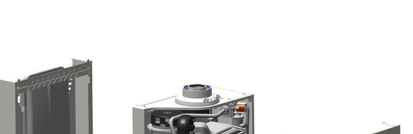
Contents

     1     Introduction ....................................................................................................................................4
     2     Rules & Regulations (Symbols) .....................................................................................................5
     3     Technical specifications ..................................................................................................................7
     4     Dimensions ...................................................................................................................................9
     5     Delivery package.......................................................................................................................... 10
     6     Boiler description..........................................................................................................................10
     7     Boiler photo components list ........................................................................................................ 11
     8     Mounting boiler frame .................................................................................................................. 12
           8.1     Wall frame ......................................................................................................................... 13
     9     Connecting boiler ......................................................................................................................... 14
           9.1     Central heating system ..................................................................................................... 14
           9.2     Expansion vessel ..............................................................................................................15
           9.3     Water quality ..................................................................................................................... 15
           9.4     Heating systems with plastic pipes ................................................................................... 17
           9.5     Gas connection in general ................................................................................................ 17
           9.5.1 Natural gas connection (NG) ............................................................................................ 17
           9.5.2 Propane gas connection (LPG).........................................................................................17
           9.5.3 House pressure regulator .................................................................................................18
           9.5.4 Dimensioning of the low pressure gas line ....................................................................... 18
           9.5.5 De-aerating the LPG tank ................................................................................................. 18
           9.6     Hot water supply ...............................................................................................................19
           9.7     Condensation drain pipe ................................................................................................... 19
           9.8     Flue gas exhaust system .................................................................................................. 23
           9.8.1 Flue terminal locations ...................................................................................................... 24
           9.8.2 Dimensioning of the flue gas and air intake duct ............................................................ 27
           9.9     Fitting the boiler onto the boiler frame ............................................................................. 29
     10    Electrical connection ....................................................................................................................31
           10.1 One controller, OpenTherm and BUS connection ............................................................. 32
           10.2 Room thermostat volt free connection ..............................................................................32
           10.3 ATAG Central Heating volt free timer connection..............................................................32
           10.4 ATAG Hot Water volt free timer connection ......................................................................32
           10.5 DHW sensor connection ................................................................................................... 32
           10.6 ATAG Outside sensor........................................................................................................ 32
           10.7 230V Control Block (230V live output) ..............................................................................32
           10.8 230V Control Block (SwL Switched live) ........................................................................... 32
           10.9 Electrical diagram .............................................................................................................33
     11    Filling system ............................................................................................................................... 34
           11.1 Hot water supply ...............................................................................................................34
     12    Boiler controls .............................................................................................................................. 35
           12.1 Controls and explanation of the functions .........................................................................36
     13    Commissioning the boiler ............................................................................................................. 37
           13.1 Settings ............................................................................................................................. 39
           13.2 Parameter chapter ............................................................................................................ 39
     14     Isolating the boiler .......................................................................................................................40
     15    Commissioning ............................................................................................................................. 41
           15.1 Checking the CO2 .............................................................................................................42
           15.2 Checking flue integrity.......................................................................................................45
           15.3 CO and combustion checks ............................................................................................. 46
     16    Routine servicing ..........................................................................................................................48
           16.1 Flow restrictor ...................................................................................................................52
           16.2 Component replacement................................................................................................... 52
           16.3 User's instructions ............................................................................................................. 52
           16.4 Warranty............................................................................................................................ 52
     17    Error codes and fault finding .......................................................................................................53

     Annex A         System water additives .....................................................................................................54
     Annex B         Declaration of conformity .................................................................................................. 55
     Annex C         Short parts list ...................................................................................................................56

         Work on the installation should only be carried out by qualified
         personnel with calibrated equipment and appropriate tools.

Installation & Servicing instructions ATAG iC-Range                                                                                                             3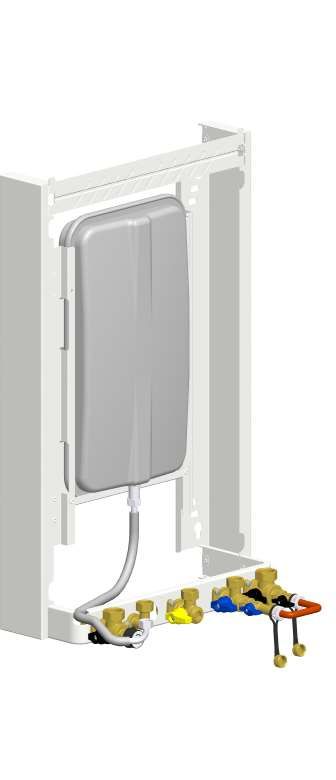
1   Introduction

        These instructions describe the functioning, installation, use and primary maintenance of ATAG central heating
        boilers for the United Kingdom.

        These instructions are intended for the use of Gas Safe registered installers in connection with the
        installation and putting into operation of ATAG boilers. It is advisable to read these instructions thoroughly,
        well in advance of installation. Separate instructions for use are supplied with the boiler for users of ATAG
        central heating boilers. ATAG is not liable for the consequences of mistakes or shortcomings which have
        found their way into the installation instructions or user’s manual. Further, ATAG reserves the right to alter its
        products without prior notification.

        When delivering the boiler, give the customer clear instructions concerning its use; present the
        customer with the user’s manual and warranty card.

        Each boiler is fitted with an identification plate. Consult the details on this plate to verify whether the boiler is
        compliant with its intended location, e.g.: gas type, power source and exhaust classification.

        On completion of the installation the installer or commissioning engineer must fill out and complete the
        Benchmark Commissioning Checklist found on page 59 of this manual and hand this to the customer
        for future record keeping. The Benchmark Service Record must also be completed by the service agent
        following each service call, and return to the customer.

4                                                                              Installation & Servicing instructions ATAG iC-Range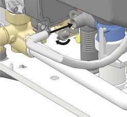
2      Rules & Regulations (Symbols)

       The following regulations apply to installation of ATAG central heating boilers:

       Legislation and Regulations.
       Gas Safety (Installation and Use). All gas appliances must by law, be installed by a competent person, eg.
       Members of Gas Safe Register and in accordance with the current Gas Safety Regulation. Failure to install
       appliance correctly could lead to prosecution.
       All Gas Safe registered installers carry a Gas Safe ID card and have a registration number. You can call Gas
       Safe Register directly on 0800 408 5577.

       In addition to the above regulations this appliance must be installed in compliance with the current IEE
       Regulations and Building Regulations. Regulations and bye laws of the Local Water Authority and the
       Current Health and Safety Regulation.

       The Benchmark Scheme
       Benchmark places responsibilities on both manufacturers and installers. The
       purpose is to ensure that customers are provided with the correct equipment
       for their needs, that it is installed, commissioned and serviced in accordance
       with the manufacturer’s instructions by competent persons and that it meets the
       requirements of the appropriate Building Regulations. The Benchmark Checklist can be used to demonstrate
       compliance with Building Regulations and should be provided to the customer for future reference.

       Installers are required to carry out installation, commissioning and servicing work in accordance with the
       Benchmark Code of Practice which is available from the Heating and Hotwater Industry Council who manage
       and promote the Scheme.
       Visit www.centralheating.co.uk for more information.

       The current Electricity at Work Regulation must be complied with and also be in accordance with the relevant
       and current editions of the British Standards.
       The ATAG iC boiler is a certified appliance and must not be modified or installed in any way contrary to
       this Installation Manual. Manufacturers instructions must not be taken, in any way, as overriding statutory
       obligations.
       The ATAG iC boiler is a central heating boiler with an integrated hot water function. The boiler must be
       connected according to these instructions and all installation norms in respect of the part of the boiler to be
       connected.

       The appliance is not to be used by children or persons with reduced physical, sensory or mental
       capabilities, or lack of experience and knowledge, unless they have been given supervision or
       instruction.

       Children being supervised not to play with the appliance.

       Observe the following rules of safety:
       - All work on the boiler must take place in a dry environment.
       - ATAG boilers may never be in operation without their housing, except in connection with maintenance or
         adjustments (see Chapter 15 and 16).
       - Never allow electrical or electronic components to come into contact with water.

       Carry out the following tasks in connection with maintenance, etc. to an already-installed boiler:
       - Shut down all programs
       - Close the gas isolation valve
       - Shut down the 230V power supply
       - Close the shut off valve of the boiler’s cold water supply
       See chapter 15 and 16 for further instructions.

Installation & Servicing instructions ATAG iC-Range                                                                      5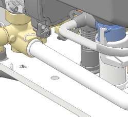
Take note of the following when maintenance or adjustments are needed:
    - The boiler must be able to function during these activities; for this reason, the boiler’s 230V power supply,
       gas pressure and water pressure must be maintained. Ensure that there is not a source of potential
       danger during these activities.

    Following maintenance or other activities; always check the installation of all parts through which
    gas flows (using leak detection spray).

    The following (safety) symbols may be encountered in these installation instructions and on the boiler
    (packaging):

    Boiler must be stored away from frost.

    Protect packaging and/or contents from damage as a result of insufficient care taken during
    transport.

    Protect the boiler from weather conditions during transport and storage whilst still in its packaging.

    If and how to clamp when using transport trucks with clamp equipment.

    If and how to transport when using a rolling jack.

    The whole packaging is made of recycled materials and can be recycled again.

    Transport and place the boiler in its packaging in this position.

    Do not to step on or stand on the package.

    An assembly or dismantling must be carried out.

    Pay extra attention in connection with a particular operation.

    Useful tip or advice

    Disposal of the product
    This product should be handed in at a designated collection point, e.g. by handing it in at a duly authorized
    reseller when purchasing a similar product, or at an authorized collection site for recycling products wich
    contains electrical and electronic equipment (EEE) and batteries and accumulators. Because of the
    potentially hazardous substances that usually accompany EEE, improper handling of this type of waste could
    have a possible impact on the environment and human health.
    Your cooperation in the proper disposal of this product will contribute to the effective usage of natural
    resources.
    For more information on recycling this product, please contact your city office, local waste disposal facilities,
    official service for chemical waste or landfill site.

6                                                                       Installation & Servicing instructions ATAG iC-Range
3 Technical specifications
Technical specifications Natural gas
ATAG iC-Series
Boiler type iC 24 iC 28 iC36 iC 40 iC Economiser Plus 27 iC Economiser Plus 35 iC Economiser Plus 39
Type heat exchanger iCon1 iCon1 iCon2 iCon2 iCon1 iCon2 iCon2
CE product identification number (PIN) 0063CQ3634
Country of destination UK
Qmin input min. CH & DHW (Hi) kW 4.5 4.5 6.2 6.2 4.5 6.2 6.2
Qn input nominal CH (Hi) kW 21.6 21.6 28.8 28.8 21.6 28.8 28.8
Qr adjusted input CH (Hi) kW 21.6 21.6 28.8 28.8 21.6 28.8 28.8
Qmin input min. CH & DHW (Hs) kW 5.0 5.0 6.9 6.9 5.0 6.9 6.9
Qn input nominal CH (Hs) kW 24.0 24.0 32.0 32.0 24.0 32.0 32.0
Qnw input nominal DHW (Hi) kW 24.0 27.3 35.4 37.9 28.3 36.3 37.9
Qnw input nominal DHW (Hs) kW 26.7 30.3 39.3 42.1 31.4 40.3 42.1
Pmin output min. CH (50/30°C) kW 5.0 5.0 6.9 6.9 5.0 6.9 6.9
Pn output nominal CH (50/30°C) kW 23.2 23.2 31.2 31.2 23.2 31.2 31.2
Pmin output min. CH (80/60°C) kW 4.4 4.4 6.1 6.1 4.4 6.1 6.1
Pn output nominal CH (80/60°C) kW 21.2 21.2 28.3 28.3 21.2 28.3 28.3
Pww output DHW kW 23.5 26.8 34.7 37.1 30.0 38.4 40.1
NOx class EN15502-1 6
O2 (full load) % 4.7
CO2 (full load) % 9.0
Appliance type B23, B33, C13, C33, C43, C53, C63, C83, C93
Flue gas temperature class T100
Max. flue resistance at Qnw/Qn Pa 130 153 191 143 151 140 148
Flue gas temperature CH (80/60°C full load) °C 59
Flue gas temperature CH (50/30°C full load) °C 34
Flue gas mass flow (full load DHW) g/s 10 11 14 15 11 14 15
Flue gas temperature CH (36/30°C low load) °C 30 30 30 30 30 30 30
Gas categories II2H3P
Gas pressure 2H / 3P mbar 20 / 37
Gas consumption max. G20 m3/hr 2.54 2.89 3.75 4.01 3.00 3.84 4.01
Current V/Hz ~ 230/50
Degree of protection acc. EN 60529 IPX4D (B22/B33 IPX0D)
Overrun time pump CH sec 60
Overrun time pump DHW sec 20
PMS water pressure CH min./max. bar 0.8 / 2.5
Flow temperature max. °C 85
Available pump height CH kPa 25 25 20 20 25 20 20
PMW water pressure DHW min./max. bar 0.5 / 8
DHW temperature setting (Tin=10°C) °C 60 60 60 60 60 60 60
Threshold DHW l/min 1.5 1.5 1.5 1.5 1.5 1.5 1.5
DHW flow (Tin=10°C, DT=35°C) l/min 10.1 11.5 14.9 16.2 12.6 16.1 17.0
DHW flow (Tin=10°C, DT=50°C) l/min 6.7 7.7 10.0 10.7 8.6 11.0 11.5
SAP Annual Efficiency NG % 89.7 89.7 89.7 89.7 89.7 89.7 89.7
Weight boiler + jig (empty) kg 41 41 44 44 43 46 46
Content DHW part l 0.3 0.3 0.3 0.3 0.6 0.6 0.6
Technical specifications Propane (3P)
ATAG iC-Series
Boiler type iC 24 iC 28 iC36 iC 40 iC Economiser Plus 27 iC Economiser Plus 35 iC Economiser Plus 39
Type heat exchanger iCon1 iCon1 iCon2 iCon2 iCon1 iCon2 iCon2
O2 (full load) % 5.1
CO2 (full load) % 10.3
Restriction diameter/marking mm 4.10/41 4.10/41 4.60/46 4.60/46 4.10/41 4.60/46 4.60/46
Pre pressure mbar see data plate LPG
Input CH (DHW) (Hi) kW 21.6 (23.9) 21.6 (27.3) 28.8 (35.4) 28.8 (37.9) 21.6 (28.4) 28.8 (36.4) 28.8 (38.3)
Gas consumption max. G31 kg/h 1.90 2.16 2.80 3.00 2.24 2.87 3.00
Gas consumption max. G31 m3/h 1.00 1.14 1.48 1.58 1.18 1.51 1.58
Modulation range CH (80/60°C) kW 8.3- 21.2 8.3- 21.2 19.1 - 28.3 19.1 - 28.3 8.3- 21.2 19.1 - 28.3 19.1 - 28.3
Modulation range CH (50/30°C) kW 9.0 - 23.2 9.0 - 23.2 20.8 - 31.2 20.8 - 31.2 9.0 - 23.2 20.8 - 31.2 20.8 - 31.2
Installation & Servicing instructions ATAG iC-Range 7
ErP specifications according to European Guideline 2010/30/EU
        Brand                                                                                                     ATAG
        Boiler type                                                    iC 24    iC 28    iC36        iC 40      iC Economiser Plus 27   iC   Economiser Plus   35   iC Economiser Plus 39
        Condensing boiler                                               yes      yes      yes         yes               yes                       yes                       yes
        Combination heater                                              yes      yes     yes          yes               yes                      yes                        yes
        Declared load profile DHW                                        XL       XL      XXL          XXL               XXL                      XXL                        XXL
        Seasonal space heating energy efficiency class CH                  A        A        A           A                 A                         A                         A
        Water heating energy efficiency class DHW                          A        A        A           A                 A                         A                         A
        Pn Power output                                     kW          21       21       28           28                21                       28                         28
        QHE Annual energy consumption                       GJ          69       69       104         115                69                       104                       115
        AEC Annual electricity consumption DHW              kWh         49       51       52          52                 57                       52                         52
        AFC Annual fuel consumption DHW                     GJ          17       17       21          21                20                        20                         20
    +   ηs Seasonal space heating energy efficiency CH        %           94       94       94          94                94                        94                         94
        ηWH Water heating energy efficiency DHW               %           85       84       90          90                94                        96                         96
        LWA Sound power level, indoors                      dB          46       46       48          48                46                        48                         48

        P4 nominal output (80/60°C)                         kW         21.2     21.2     28.3         28.3             21.2                      28.3                      28.3
        P1 30% of nominal output (36/30°C)                  kW          7.2     7.2       9.6         9.6              7.2                       9.6                        9.6
        η4 efficiency at nominal input (GCV)                  %          88.3     88.3     88.6         88.6             88.3                      88.6                      88.6
        η1 efficiency at 30% of the nominal input (GCV)       %           99.4     99.4     99.5       99.5               99.4                     99.5                       99.5
        elmax                                               kW         0.074    0.074    0.074       0.074             0.074                    0.074                      0.074
        elmin                                               kW         0.021    0.021    0.032       0.032             0.021                    0.032                      0.032
        PSB                                                 kW         0.004    0.004    0.004       0.004             0.004                    0.004                      0.004
        Pstby heat loss                                     kW         0.055    0.055    0.055       0.055             0.055                    0.055                      0.055
        Qelec Daily electricity consumption DHW             kWh        0.249    0.249    0.240       0.240            0.264                     0.238                     0.238
        Qfuel Daily fuel consumption DHW                    kWh        22.700   22.961   27.315      27.315           25.649                    25.122                    25.122
        Temperature Control                                                                       Weathercompensator (outside sensor)
        Class of temperature control                                     II       II       II          II                II                        II                        II
    +   Contribution of temperature control                 %            2        2        2           2                 2                         2                         2

        Package

    =   Seasonal space heating energy efficiency of package   %           96       96       96          96                96                        96                         96
        CH Package Energy Label                                          A        A        A           A                 A                         A                         A
        DHW Package Energy Label                                         A        A        A           A                 A                         A                         A

8                                                                                                             Installation & Servicing instructions ATAG iC-Range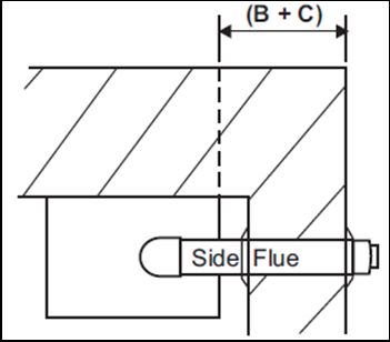
4          Dimensions

                             B
                         A
                             B

                                                                                     ATAG iC-Series
                                                      iC 24   iC 28   iC36   iC 40     iC Economiser Plus 27   iC   Economiser Plus   35   iC Economiser Plus 39
 Flue gas / Air intake           A/B      mm                                             60/100
 Gas connection                           mm                                               22
 CH Flow connection                       mm                                               22
 CH Return connection                     mm                                               22
 Condensate drain connection              mm                                              21.5
 Cold water connection                    mm                                               15
 DHW connection                           mm                                               15

Installation & Servicing instructions ATAG iC-Range                                                                                                                9
5 Delivery package
The delivery package of the boiler is composed as follows:
- Boiler frame;
- Boiler with cover;
- Automatic air vent (in boiler);
- Safety valve 3 bar (in boiler);
- Three way valve (in boiler);
- Automatic by-pass (in boiler);
- DHW flow restrictor (in boiler);
- Economiser (only economiser-versions)
- Expansion vessel 8 litre / 1 bar (in boiler frame);
- Isolation valves with drainpoint (CH 2x, 1x DHW cold)
- Gas isolating valve;
- Filling loop;
- Mains cold water filter;
- Fittings consisting of plugs and screws;
- Outside sensor;
- Drawing template;
- Installation instructions;
- User manual;
- Warranty Card.
The following components are not present in the boiler packaging as a standard and should be included in
the installation according to the requirements:
- Flue system;
- External controls.
6 Boiler description
The ATAG iC is a room sealed, condensing and modulating CH boiler equipped with an integrated hot water
supply.
The boiler is equipped with a compact stainless steel heat exchanger with smooth pipes. It is a well thought-
out principle using sustainable materials.
The boiler burns natural gas to supply heat (LPG conversion kits available). This heat is transferred in
the heat exchanger to the water in the CH installation. The rapid cooling off of the flue gases causes
condensation. This results in a very high efficiency. The condensate that is formed, has no negative impact
on the heat exchanger and it's operation, and is removed through the internal siphon. This feature requires a
condensate drain pipe connected to the drain of the building.
The boiler is equipped with an intelligent control system. The boiler anticipates on the heat demand of the
heating installation or hot water demand. This will cause the boiler to tune its capacity to the installation. This
means that the boiler will function longer and at a low level.
If an outside sensor is connected, the control system is able to function, depending on the weather. This
means that the control system measures the outside temperature and the flow water temperature. On the
basis of this information the control system calculates optimum flow water temperature required for the
installation.
The boiler has been tested according to valid CE standards and has a CE certificate and >88% Efficient
SEDBUK 2009.
Statement: No banned materials including asbestos, mercury, CFC's have or will not be included in
the product.
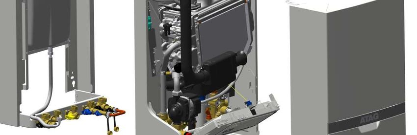
10 Installation & Servicing instructions ATAG iC-Range7 Boiler photo components list
13
14
24 5
6
3
16
1
2
T1 4
P1 10
T2 F1
18
11 15
T3
12 8
7 9
19
20 21 22 23 17
A W G K R C
ATAG iC Figure 7.a
1 Heat exchanger 9 Control panel 17 Safety valve
2 Ignition unit 10 Three-way valve 18 DHW Economiser
3 Fan unit 11 Circulation pump 19 Siphon
4 Air supply damper 12 Filling loop 20 Isolation valve flow CH
5 Gas valve 13 Flue gas exhaust 21 Isolation valve gas
6 Automatic de-aerator 14 Combustion air supply 22 Isolation valve cold water
7 DHW plate heat exchanger 15 Boiler data plate 23 Isolation valve return CH
8 Control unit 16 Expansion vessel 24 Flue non return valve
T1 Flow sensor G Gas pipe
T2 Return sensor A Flow pipe CH
T3 Hot water sensor R Return pipe CH
F1 DHW flow sensor C Condensation pipe
P1 Water pressure sensor K Cold water pipe
W Hot water pipe
Installation & Servicing instructions ATAG iC-Range 118 Mounting boiler frame
Install the boiler in a boiler room in accordance to the actual local regulations BS5440-2:2009.
The installation location of the boiler has to be, and remain, frost-free. The boiler casing is splash water tight
(IPX4D) and is suitable to be installed in e.g. a bathroom.
It is NOT necessary to have a purpose provided air vent in the room or internal space in which the boiler is
installed. Neither is it necessary to ventilate a cupboard or compartment in which the boiler is installed, due
to the extremely low surface temperature of the boiler casing during operation. Therefore the requirements of
BS5440:2 may be disregarded.
The boiler can be mounted practically to any wall with the wall frame and the enclosed fixing equipment. The
wall must be flat and of sufficient strength in order to be able to carry the boiler weight with its water content.
Above the boiler there must be at least 210 mm working space in order to be able to fit a horizontal
concentric flue system to the rear (See chapter 9.8 for more flue options). Make sure there is sufficient
service space around the boiler according figure 8.a. The location of the boiler can be determined by using
the template.
The wall frame allows the possibility to pre-fit the complete heating and DHW system before fitting the boiler.
Also the flue system can be prepared. Finally fitting of the flue system is done after fitting the boiler. See next
page for all options for connection the heating, DHW, condensate, flue and gas installation.
Before hanging the boiler to the boiler frame remove the front panel of the boiler first. The front panel is also
the air cabinet and is attached to the boiler case with 2 fasteners (A and B) (see figure 8.a).
Note that there is an earth cable (when present) to disconnect when removing the boiler front panel.
Free space for removing the connector is about 400 mm. Remember to connect this earth cable
(when present) when placing back the boiler front panel and take care the wire does not get stuck
between front panel and boiler. Always replace and turn the 2 screws tight in the fasteners A and B.
Service dimensions (in mm) Figure 8.a
See chapter 9.8 for further procedure to fit the boiler onto the boiler frame.
12 Installation & Servicing instructions ATAG iC-Range8.1 Wall frame
- Position the boiler frame against the wall using the template and a level.
- Use the level for horizontal positioning and checking the vertical position.
- Drill 4x ø10mm holes, 60mm deep
- Press the nylon wall plug (ø10x55mm) in the holes
- Mount the boiler frame to wall with the 4 coach screws (ø8x60mm) using a 13mm wrench
The boiler frame allows pipe work to be installed behind the boiler.
Note that there are free spaces on the left and right of the expansion vessel. Do not guide pipe work
in front of the expansion vessel. The pipe work must be installed at least 10mm inside the front of the
frame.
= free space for piping
ATAG i-Serie template and iC-Range boiler frame Figure 8.1.a
Installation & Servicing instructions ATAG iC-Range 139 Connecting boiler
The boiler has the following connection pipes;
- The central heating pipes.
The boiler is provided with isolation valves on the flow and return pipe to which the installation can be
connected by means of 22mm compression fittings;
- The gas pipe.
The boiler is provided with an isolation gas valve to which the gas line can be fitted with 22mm
compression fitting;
- The condensation drain pipe.
It consists of a 25mm flexible plastic pipe. The drain pipe can be connected to this by means of an open
connection;
- The flue gas exhaust system and air supply system.
It consists of a concentric connection 60/100 mm.
- Cold and hot water pipes.
The boiler is provided with a isolation valve on the cold water inlet. The DHW installation can be
connected by means of 15mm compression fittings.
See following chapters for detailed information regarding each connection.
It is advisable to clean all of the boiler’s connecting pipes and/or to power flush the installation
before connecting it to the boiler.
9.1 Central heating system
Connect the central heating system according to the current regulations.
The boiler pipes can be connected to the installation by means of 22mm compression fittings. For connecting
to thick-walled pipe (welded or fitted), adapters should be used.
The boiler has a self-adjusting and self-protecting control system for the load. This involves checking the
temperature difference between the flow and return water. Table 9.1.a shows the water displacement the
circulation pump can deliver for a particular installation resistance.
If the installation resistance is higher than the value stated, the control system will adjust the load until a
temperature difference between flow and return water is reached that is acceptable for the control system.
When the temperature difference still remains too high the boiler will switch itself off and wait until the high
temperature differential between the flow and return water has decreased again.
Pump type Grundfos UPM3 15-75
iC 24 iC 28 iC36 iC 40 iC Economiser Plus 27 iC Economiser Plus 35 iC Economiser Plus 39
Water flow rate l/min 15.2 15.2 20.3 20.3 15.2 20.3 20.3
l/h 912 912 1218 1218 912 1218 1218
Permissible installation resistance kPa 25 25 20 20 25 20 20
mbar 250 250 200 200 250 200 200
Installation resistance table 9.1.a
The control system will, if an unacceptable temperature difference is detected, repeatedly try to establish a
water flow. If this does not succeed, the boiler will block itself (code 154).
The boiler is NOT equipped with a built-in internal filter.
Advice: ATAG Heating Technology Ltd recommend the installation of an in-line filter installed into the
heating return as close to the boiler as possible. ATAG Heating Technology Ltd recommend the use
of the:
ATAG iGuard Magnetic filter 22mm (Plastic) FC000100, (Brass) FC000200, 28mm (Brass) FC000250.
14 Installation & Servicing instructions ATAG iC-RangeThe boiler is not suitable for installations that are equiped with “open” expansion tanks.
Additives in the installation water are only permitted in consultation with the country distributor. See
chapter 9.3 for detailed information.
9.2 Expansion vessel
The iC boilers are featured with a built-in expansion vessel with a capacity of 8 litres and a pre-pressure
charge 1 bar. If the expansion vessel size is insufficient for the CH system, an additional expansion must be
installed. The additional expansion vessel should, together with the built-in expansion vessel, be sized to the
water content of the installation. The pre-pressure charge depends on the height of the installation above the
installed expansion vessel. See Table 9.2.a.
The (additional) expansion vessel should be connected as closely as possible in the return pipe near
the boiler.
Installation height above the expansion vessel pre-charge pressure of the expansion vessel
5m 0.5 bar
10m 1.0 bar
15m 1.5 bar
table 9.2.a
The pressure relief valve outlet is combined with the condensate outlet (see figure 9.9.e on page 29).
9.3 Water quality
Fill the installation with mains cold water.
In most cases, a heating system can be filled with water according to national standards for water and
treatment of this water is not necessary.
In order to avoid problems with the CH-installations, the quality of the filling water has to meet the
specifications mentioned in table 9.3.a:
If the filling water does not meet the required specifications, you are advised to treat the water to such an
extent that it does meet the required specifications.
The warranty becomes invalid, if the installation is not being flushed and/or the quality of the filling
water does not meet the specifications recommended by ATAG Heating Technology Ltd. Always
contact ATAG Heating Technology Ltd in advance, if things are not clear or you wish to discuss any
deviations. Without approval, the warranty becomes invalid.
Installation:
- The use of groundwater, demi-water and distilled water is prohibited. (on the next page you will find an
explanation of these definitions)
- If the mains water quality meets the specifications mentioned in table 9.3.a, you can start flushing the
installation before installing the device.
- Whilst flushing, corrosion products (magnetite), fitting products, cutting oil and other undesirable products
have to be removed.
- Another possibility is to remove the pollution by installing a filter. The filter type has to fit the type and
grain size of the pollution. ATAG Heating Technology Ltd recommends filter usage.
- In this case, the whole piping system should be taken into consideration.
- The CH-installation has to be properly vented before using the system. For that purpose, we refer to the
commissioning chapter.
- If a regular water top up is required (>5% on an annual basis), then there is a structural problem and
an installer has to solve the problem. Regularly adding fresh water to the system also adds additional
calcium and oxygen implying that magnetite and calcium residues can continue. The result may be
blockages and/or leakages.
- The use of anti-freeze and other additives requires periodical quality checks of the filling water in
accordance with the period laid down by the additives supplier.
Installation & Servicing instructions ATAG iC-Range 15- Chemical additions are to be avoided and should only be used after ATAG Heating Technology Ltd has
approved their corresponding use.
- Should you wish to achieve the required water quality by using chemical additives, then this is your own
responsibility. The warranty on the product delivered by ATAG Heating Technology Ltd expires, if the
water quality does not meet ATAG Heating Technology's specifications or the chemical additives have not
been approved by ATAG Heating Technology Ltd.
- On installation and during additions or changes at a later stage, ATAG Heating Technology Ltd
recommends to keep a record of the type of water used, its quality at the time, and if applicable, which
additives and quantities were added.
Parameter Value
Water type Potable water
Softened water
pH 6.0-8.5
Conductivity (at 20°C in µS/cm) Max. 2500
Iron (ppm) Max. 0.2
Hardness (°dH / ppm):
Installation volume/capacity 1-12 °dH / 17-214 ppm
=20 l/kW
Oxygen No oxygen diffusion allowed during operation.
Max. 5% filling water addition annually
Corrosion inhibitors Refer to Additives Attachment
pH increasing or lowering agents Refer to Additives Attachment
Anti-freeze additives Refer to Additives Attachment
Other chemical additives Refer to Additives Attachment
Solid substances Not allowed
Residues of processing water not forming part of the Not allowed
drinking water
table 9.3.a
Water quality in DHW facility
Parameter Value
Water type Potable water
pH 7.0-9.5
Conductivity (at 20°C in µS/cm) Max. 2500
Chloride (ppm) Max. 150
Iron (ppm) Max. 0.2
Hardness (°dH / ppm): 1-12 °dH / 17-214 ppm
Number of bacterial colonies at 22°C (number/ml). pr Max. 100
EN ISO 6222
table 9.3.b
- When the amount of chloride is above the required specifications mentioned above in table 9.3.b, in case
of the use of a combi boiler will void the warranty for DHW parts of the boiler.
Water type definition:
Potable water: Tap water compliant with the European drinking water guideline:
98/83/EG dated 3 November 1998.
Softened water: Water with partly de-ionised calcium and magnesium.
Demi-water: Virtually completely demineralised water (very low conductivity)
Distilled water: Water no longer containing minerals.
16 Installation & Servicing instructions ATAG iC-Range9.4 Heating systems with plastic pipes
When connecting or using an underfloor heating system, designed with plastic pipes, or plastic pipes are
used elsewhere in the installation, one should ensure that the plastic pipes used comply with the DIN
4726/4729 standard. It is set out in this standard that the pipes may not have oxygen permeability higher
than 0.1 g/m³.d at 40°C. If the system does not comply with this DIN standard, the underfloor heating
component will have to be separated from the central heating appliance by means of a plate exchanger.
No recourse can be made to the terms of the warranty in the event of failure to observe the
regulations pertaining to plastic underfloor heating pipes.
9.5 Gas connection in general
The local gas supplier should be consulted, at the installation planning stage, in order to establish the
availability of an adequate supply of gas. An existing service pipe must NOT be used without prior
consultation with the local gas supplier.
ATAG supplies boilers suitable for natural gas only. Verify the identification plate on the boiler if the
boiler is suitable for the gas kind on site.
For use with propane gas, the LPG conversion kit has to be installed, see separate conversion
instructions.
Make sure that the gas pipe work does not contain dirt, particularly with new pipes.
The complete installation MUST be tested for gas tightness and purged as described in the above
code.
The boiler connection is provided with an isolation valve with 22mm compression fitting, into which the gas
line can be fitted.
9.5.1 Natural gas connection (NG)
The gas supply must comply to the current Gas Safety, Installation & Use Regulations, in accordance with
BS.6891.
The nominal inlet working gas pressure measured at the appliance should be 21 mbar +/- 2 mbar for Nat
gas (G20). Allowing for the acceptable pressure loss of 1 mbar across the installation pipework, it can
be assumed that a minimum permitted operating pressure of 18 mbar will be delivered to the inlet of the
appliance. (Reference BS 6400-1 Clause 6.2 Pressure Absorption). When tested at the gas valve, the
pressure drop from the meter to the gas valve must not be more than 4 mbar.
9.5.2 Propane gas connection (LPG)
For use with propane gas, the LPG conversion kit has to be installed, see separate conversion instructions.
The LPG installation must comply to the current Gas Safety, Installation & Use Regulations, in accordance
with BS:6891
Installing of a LPG installation should only be done by a registered LPG installer.
The tank must be provided with a high pressure regulator with a minimum capacity of 24 kg/h to reduce
the tank pressure from 5 to 1.5 bar. The 1.5 bar high pressure gas line should have a minimum diameter of
15mm. In the high pressure gas line a house pressure regulator must be installed. When tested at the gas
valve, the pressure drop from the pressure regulator to the gas valve must not be more than 3.8 mbar.
Installation & Servicing instructions ATAG iC-Range 179.5.3 House pressure regulator
Each gas appliance which is connected to the propane installation must be provided with its own
house pressure regulator. The house pressure regulator is a third party delivery.
The house pressure regulator must have a minimum capacity of 10 kg/h / 37 mbar and a CE certification.
ATAG advices to install the house pressure regulator as close as possible to the boiler. When placing the
regulator inside, a discharge drain of ø6mm must be installed. The discharge drain must be directed outdoor.
In case of a discharge the gasses will go outside.
If fitting the regulator outside the regulator should be protected against influences of the weather. The (de-)
aeration must be positioned downwards (see figure 9.5.3.a).
ATAG advices to install measure points on all gas line parts to have the possibility to check for pressure loss.
example propane installation figure 9.5.3.a
Pre-pressure must be adjusted to 37 mbar by means of the house pressure regulator. The maximum
permitted closing pressure may be 5 mbar higher than the maximum pre-pressure.
A too high closing pressure in the low pressure gas line can be caused by a high resistance or jam in this gas
line. When the closing pressure keeps increasing the valve in the regulator is not closing correctly. In this
case the regulator should be replaced.
9.5.4 Dimensioning of the low pressure gas line
The gas line from the house pressure regulator to the boiler must have the dimensions according the table
below.
Pump type Grundfos UPM3 15-75
iC 24 iC 28 iC36 iC 40 iC Economiser Plus 27 iC Economiser Plus 35 iC Economiser Plus 39
Diameter gas line m m m m m m m
ø15mm 3 - - - - - -
ø22mm 30 18 18 18 18 18 18
ø28mm - 30 30 30 30 30 30
Dimensioning low pressure gas line table 9.5.4.a
9.5.5 De-aerating the LPG tank
When placing a new or revised LPG tank the tank must always be de-aerated.
ATAG advices to inform the gas supplier that a central heating boiler is connected to the LPG tank. For the
boiler it is absolutely necessary that the tank is free of air. When not the boiler will give ignition problems and
will not function.
ATAG advices to measure the content of O2 . This value should be lower than 1.3%. Contact the gas
supplier in case of doubt.
18 Installation & Servicing instructions ATAG iC-Range9.6 Hot water supply
Connection of the drinking water installation should be done according to the Water Supply (Water Fittings)
Regulations and Scottish Water Byelaws.
The ATAG iC boiler is fitted with a stainless steel plate heat exchanger for producing domestic hot water. The
boiler does not have a hot water store and in case of a demand for hot water the boiler will heat the domestic
water flowing through the plate heat exchanger up to 60°C (adjustable) instantaneous.
The water mains installation must comply with the Water Supply (Water Fittings) Regulations and Scottish
Water Byelaws. See also chapter 9.3.
In regions with a water hardness value higher than 200ppm (2.67 mmol/l), calcium deposits should
be removed from the plate heat exchanger on a regular basis. If problems occur when using sanitary
water with a chlorine content higher than 150 mg/l, no recourse can be made to the terms of the
warranty.
In order to prevent calcification ATAG recommends applying a water softener.
ATAG recommends the use of for instance AlphaPhos for cleaning plates exchangers.
The hardness of the water is variable in the United Kingdom. The water company can provide exact
information about this.
The domestic water installation can be connected to the boiler by means of 15mm compression fittings.
If the mains is fitted with water meter, check valves or loose jumper stop cock, then a DHW expansion device
must be fitted.
The boiler is provided with a DHW flow restrictor. The flow restrictor ensures that a quantity of water supplied
has a guaranteed temperature of 60 °C (assuming a cold water temperature of 10°C). The amount of water
is virtually unaffected by the water pressure.
After installation, check the hot water flow rate with a fully opened hot water tap,
If required the flow restrictor can be removed. See chapter 16.1.
9.7 Condensation drain pipe
The ATAG condensing boiler has the >88% Efficient SEDBUK 2009 for high energy efficiency in heating and
domestic hot water. The ATAG wall hung gas fired condensing boiler contain a siphonic condensate trap to
collect and realease condensate. The amount of condensate formed is determind by the type of boiler and
the water temperature produced by the boiler.
Condensate pipework.
Use plastic pipework of an internal diameter no less then 19mm ID (typically 22mm OD).
Routing of the pipework,
The condensate pipework must fall at least 45mm per metre away from the boiler, taking the shortest
practicle route to the termination point.
Support the pipe at least every 50 cm for near horizontal sections and 1 metre for vertical sections.
Wherever possible, the condensate pipework should be routed internally to prevent freezing. In order to
minimise the risk of freezing during prolonged very cold spells, one of the following methods of terminating
condensate drainage pipe should be adopted.
Internal pipework
Wherever possible, the condensate drainage pipe should be terminated at a suitable internal foul water
discharge point such as (a) an internal soil and vent stack or (b) an internal kitchen or bathroom waste pipe,
washing machine waste pipe etc. A suitable permanent connection to the foul waste pipe should be used.
Figures 9.7.1, 9.7.2(a), 9.7.2(b) show appropriate connection methods.
The possibility of waste pipes freezing downstream of the connection point should be considered when
determining a suitable connection point - e.g. a slightly longer pipe run to an internal soil stack may be
preferable to a shorter run connecting into a kitchen waste pipe discharging directly through the wall to an
external drain.
Where “gravity discharge” to an internal termination is not physically possible (e.g. the discharge point is
above the appliance location, or access is obstructed by a doorway), or where very long internal pipe runs
would be required to reach a suitable discharge point, the following measures may be adopted.
Installation & Servicing instructions ATAG iC-Range 191 Boiler 1 Boiler
2 Visible air break 2 Visible air break
3 75mm trap 3 75mm trap
4 Soil and vent stack 4 Sink, basin, bath or shower
5 Invert 5 Open end of condensate drainage pipe direct into gully 25mm
6 450mm minimum up to three storeys min below grating but above water level; end cut at 45°
7 Minimum internal diameter 19mm (fall at least 45mm per meter) 6 Sink lip
7 Minimum internal diameter 19mm (fall at least 45mm per meter)
8 Pipe size transition
9 Minimum internal diameter 30mm
10 Water/weather proof insulation
Drain requirements Figure 9.7.1 Drain requirements Figure 9.7.2 (a)
1 Boiler 1 Condensate discharge from boiler
2 Visible air break 2 Visible air break
3 Visible air break at plug-hole 3 Condensate pump
4 75 mm sink, basin, bath or shower waste trap 4 Visible air break at plug hole
5 Sink, basin, bath or shower with integral overflow 5 Sink or basin with integrated overflow
6 Open end of condensate drainage pipe direct into gully 25mm 6 75mm sink waste trap
min below grating but above water level; end cut at 45°
7 Minimum internal diameter 19mm (fall at least 45mm per meter)
8 Pipe size transition
9 Minimum internal diameter 30mm
10 Water/weather proof insulation
Drain requirements Figure 9.7.2 (b) Drain requirements Figure 9.7.3
20 Installation & Servicing instructions ATAG iC-RangeUse of a condensate pump (to an internal termination):
Condensate can be removed using a proprietary condensate pump (third party delivery), of a specification
recommended by the pump manufacturer. Condensate pump suitable for combined pressure relief valve.
The pump outlet should discharge to a suitable internal foul water discharge point, such as (a) an internal soil
and vent stack or (b) an internal kitchen or bathroom waste pipe, washing machine waste pipe etc. Figure
9.7.3 shows a typical connection method.
A suitable permanent connection to the foul waste pipe should be used and the manufacturer’s detailed
installation instructions for the pump should be followed.
External pipework
The use of an externally-run condensate drainage pipe, terminating at a suitable foul water discharge point
or purpose-designed soakaway, may be also be considered; however if this termination method is chosen
then the following measures should be adopted
- The pipe should be run internally as far as possible before going externally and the pipe diameter should
be increased to a minimum of 30mm ID (typically 32mm OD) before it passes through the wall.
- The external run should be kept as short as possible, taking the most direct and “most vertical” route
possible to the discharge point, with no horizontal sections in which condensate might collect. Do not
exceed 3 metres outside the dwelling.
- The external pipe should be insulated using suitable waterproof and weatherproof insulation (“Class O”
pipe insulation is suitable for this purpose) .
- The use of fittings, elbows etc should be kept to a minimum and any internal “burrs” on cut pipework
should be removed so that the internal pipe section is as smooth as possible.
The customer/householder should be advised that even with the above measures this type of installation
could freeze, and that if this were to occur then boiler shutdown could result, requiring remedial action -
possibly involving a chargeable engineer call-out.
Where there are likely to be extremes of temperature or wind-chill, the use of a proprietary trace-heating
system for external condensate drainage pipework, incorporating an external frost thermostat, should
therefore be considered. If such a system is used then the installation instructions of the trace heating
manufacturer and any specific recommendations regarding pipe diameter, insulation, etc. should be followed.
All other relevant guidance on condensate drainage pipe installation should also be followed.
Other cold weather protection methods approved or endorsed by boiler manufacturers and/or service
organisations may be adopted if these are considered suitable by the parties involved.
If an external soil/vent stack is used as the external termination then the connection method shown in Figure
9.7.4 should be used, together with the measures on insulation etc. as described above and shown in the
diagram.
When a rain water downpipe is used as the termination (NB only permissible if this downpipe passes to
a combined foul and rainwater drainage system) an air break must be installed between the condensate
drainage pipe and the downpipe to avoid reverse flow of rainwater into the boiler should the downpipe itself
become flooded or frozen. Figure 9.7.5 shows a suitable connection method.
Where the condensate drainage pipe is terminated over an open foul drain or gully, the pipe should terminate
below the grating level, but above water level, in order to minimise “wind chill” at the open end. Pipe drainage
will be improved if the end is cut at 45° as opposed to a straight cut. The use of a drain cover (such as
those used to prevent blockage by leaves) may offer further protection from wind chill. Figure 9.7.6 shows a
suitable connection method.
Where the condensate drain pipe terminates in a purpose-designed soakaway (see BS 6798:2014 or boiler
installation manual for soakaway design requirements) any above-ground section of condensate drainage
pipe should be run and insulated as described above. Figure 9.7.7 shows a suitable connection method.
Unheated internal areas:
Internal condensate drainage pipes run in unheated areas such as lofts, basements and garages should be
treated as external pipe.
Draining of the condensation water to the external rain guttering is not permitted in view of the
danger of freezing.
Before putting the boiler into operation fill the siphon with 150 ml of water.
Installation & Servicing instructions ATAG iC-Range 211 Boiler 1 Condensate discharge pipe from boiler
2 Visible air break 2 Pipe size transition point
3 75mm trap 3 Water/weather proof insulation
4 Soil and vent stack 4 43mm 90° male/female bend
5 Invert 5 External rain water pipe into foul water
6 450mm minimum up to three storeys 6 External air break
7 Minimum internal diameter 19mm (fall at least 45mm per meter) 7 Air gap
8 Pipe size transition 8 68 mm ø PVCu strap-on fitting
9 Minimum internal diameter 30mm 9 Minimum internal diameter 19mm
10 Water/weather proof insulation 10 Minimum internal diameter 30mm
11 End cut at 45°
Drain requirements Figure 9.7.4 Drain requirements Figure 9.7.5
1 Boiler 1 Condensate discharge pipe from boiler
2 Visible air break 2 Ground (this section of the condensate drainage pipe may be
3 38mm minimum trap run either above or below ground level); End cut at 45°
4 External length of pipe 3m maximum 3 Diameter 100mm minimum plastic tube
5 Open end of condensate drainage pipe direct into gully 25mm 4 Bottom of tube sealed
min below grating but above water level; end cut at 45° 5 Limestone chippings
6 Minimum internal diameter 19mm (fall at least 45mm per meter) 6 Two rows of three 12mm holes at 25mm centres, 50mm from
7 Pipe size transition point bottom of tube and facing away from house
8 Minimum internal diameter 30mm 7 Hole depth 400mm minimum by 300mm diameter
9 Water/weather proof insulation 8 Minimum internal diameter 19mm (fall at least 45mm per meter)
9 Pipe size transition point
10 Minimum internal diameter 30mm
11 Water/weather proof insulation
Drain requirements Figure 9.7.6 Drain requirements Figure 9.7.7
22 Installation & Servicing instructions ATAG iC-Range9.8 Flue gas exhaust system
The flue gas exhaust system and air supply system consists of:
- Flue gas pipe;
- Air supply pipe;
- Roof or wall terminal.
The flue gas exhaust system and air supply system must comply with:
The flue gas outlet and air supply installation must comply with the current regulation requirements in
accordance with BS:5440 Part 1 and 2.
The ATAG iC boiler as described in this manual is NOT suitable for a combined flue system.
The appliance concentric connection diameter is 60/100 mm, to which the flue gas outlet and air supply
system can be fitted, with or without elbow pieces. The maximum permissible pipe length is set out in Table
9.8.2.a.
For further information about the available components of the flue gas and air supply system we recommend
you consult the Flue system literature. Combinations with other brands or systems are, without written
permission from ATAG Heating, not permitted.
The ATAG flue gas system is meant, and designed, solely for the use on ATAG central heating boilers
adjusted to Nat gas or LPG. For this purpose the CE Certificate has been supplemented under the Gastec
nr: 0063CQ3634 The maximum flue gas temperatures are below 70°C (full load 80/60°C).
The proper operation may be adversely influenced by changes of or adjustments to the correct set up.
Possible warranty claims will not be honoured if incorrect changes result in non compliance with the
installation manual or local rules and regulations.
Room sealed system
Boiler Class C
Permitted only
when the air
P/A intake and the flue gas
outlet are in the same
pressure area.
LEGEND:
P/A Polypropylen / Aluminium
P/A P/A P/A
Room sealed system Figure 9.8.a
Installation & Servicing instructions ATAG iC-Range 239.8.1 Flue terminal locations
The terminal should be located where dispersal of combustion products is not unimpeded and with due
regard for the damage or discolouration that might occur to parts of the building in the vicinity (see fig
9.8.1.c).
In certain weather conditions condensation may also accumulate on the outside of the air inlet pipe. Such
conditions must be considered and where necessary insulation of the inlet pipe may be required.
In cold and/or humid weather water vapour may condense on leaving the flue terminal. The effect of such
‘plumeing’ must be considered.
The terminal must not be located in a place where it is likely to cause a nuisance, where the terminal is less
than 2m (6.6ft) above a pavement or platform to which people have access (including) any balcony or flat
roof. The terminal must be protected by a guard of durable material.
Where a terminal is fitted below a window which is hinged at the top, and where the hinge axis is
horizontal, and the window opens outwards, the terminal shall be 1m below the bottom of the window
opening.
The flue must be terminated in a place not likely to cause a nuisance.
For horizontal flue terminal direct to the rear or side through the wall (only 1 bend
and 1 wall terminal) the terminal should be placed horizontal. The flue pipe inside
the terminal is fitted in a 3 degrees angle to ensure the condensation water can run
back to the boiler. See figure 9.8.1.a.
For longer horizontal sections, the outlet system should always be fitted on an
incline (52 mm/m = 3°) sloping down towards the boiler so that no condensation
water is able to accumulate in the outlet system. The chances of icicles forming on
the outlet is minimised by causing the condensation water to run back towards the
boiler. See figure 9.8.1.b.
Figure 9.8.1.a
Figure 9.8.1.b
24 Installation & Servicing instructions ATAG iC-RangeYou can also read