A City-Scale ITS-G5 Network for Next-Generation Intelligent Transportation Systems: Design Insights and Challenges
←
→
Page content transcription
If your browser does not render page correctly, please read the page content below
A City-Scale ITS-G5 Network for
                                             Next-Generation Intelligent Transportation
                                              Systems: Design Insights and Challenges

                                            Ioannis Mavromatis, Andrea Tassi, Robert J. Piechocki, and Andrew Nix

                                         Department of Electrical and Electronic Engineering, University of Bristol, UK
                                        Emails: {ioan.mavromatis, a.tassi, r.j.piechocki, andy.nix}@bristol.ac.uk
arXiv:1806.04951v2 [cs.NI] 6 Jul 2018

                                               Abstract. As we move towards autonomous vehicles, a reliable Vehicle-
                                               to-Everything (V2X) communication framework becomes of paramount
                                               importance. In this paper we present the development and the perfor-
                                               mance evaluation of a real-world vehicular networking testbed. Our test-
                                               bed, deployed in the heart of the City of Bristol, UK, is able to exchange
                                               sensor data in a V2X manner. We will describe the testbed architecture
                                               and its operational modes. Then, we will provide some insight pertaining
                                               the firmware operating on the network devices. The system performance
                                               has been evaluated under a series of large-scale field trials, which have
                                               proven how our solution represents a low-cost high-quality framework
                                               for V2X communications. Our system managed to achieve high packet
                                               delivery ratios under different scenarios (urban, rural, highway) and for
                                               different locations around the city. We have also identified the instability
                                               of the packet transmission rate while using single-core devices, and we
                                               present some future directions that will address that.

                                               Keywords: Connected and Autonomous Vehicles, CAVs, IEEE 802.11p/DSRC,
                                               V2X, Real-World Field Trials, VANET.

                                        1    Introduction
                                        The Automotive Industry is progressively commercialising several advanced fea-
                                        tures such as lane-keeping assistance, forward collision braking, etc. Even the
                                        most pessimistic market analysis envisage that fully autonomous vehicles will
                                        flood the global market by 2025 [22]. Autonomous vehicles are expected to
                                        be equipped with several sensors that will assist their autonomous function-
                                        alities [14]. However, the most critical enabler of the full autonomy will be
                                        the communication framework [9] among the vehicles, i.e. Vehicle-to-Vehicle
                                        (V2V), and between the vehicles and the infrastructure network, i.e. Vehicle-
                                        to-Infrastructure (V2I).
                                            The communication framework is essential as the information exchanged can
                                        increase the vehicle safety, provide new services, reduce traffic jams improving the
                                        fleet routing, etc. For these reasons, 75 MHz of the spectrum have been allocated
                                        in the 5.9 GHz band for Dedicated Short Range Communication (DSRC) to
                                        be used for the Cooperative Intelligent Transportation Systems (C-ITSs). The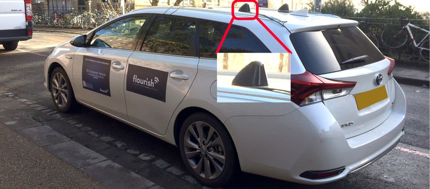
DSRC radio technology was standardized by IEEE in the 802.11p standard [5],
describing the PHY and the MAC layer of the framework, as well as in [7] and [6]
describing the networking services and the multi-channel operation respectively.
    Performance enhancement of DSRC communications is a hot research topic.
The development of a robust Vehicle-to-Everything (V2X) communication frame-
work, able to guarantee the exchange of information between the Connected and
Autonomous Vehicles (CAVs), remains a challenge. Most of the research activi-
ties on Vehicular Ad-Hoc Networks (VANETs) and the DSRC focus on computer
simulations and theoretical models (e.g. [21,12]). The importance of simulations,
as well as their limitations, were discussed in [15] showing that, in larger scale
scenarios, the existing simulation frameworks lack in accuracy and realism. To
that extent, we will focus our research on building and deploying a real-world
large-scale testbed for V2I and V2V communications that could offer:

 – Continuous availability for delay-critical applications.
 – Full-stack system implementation to support various vehicular applications.
 – Centralised coordination via a Software-Defined Networking (SDN)-like frame-
   work.
 – Open-source operating system for customisability and compatibility with
   Fog and Cloud Computing architectures [11].
 – Reduced cost for large-scale deployments.

Our experimental testbed is currently deployed in the City of Bristol, UK. Sim-
ilar activities can be found in the literature (e.g. [13,10,8]), however, only [8]
considered a V2V communication framework. The systems mentioned above
mainly rely on Commercial Off-the-Self (COTS) implementations and license-
based products. Our prototyped system relies on open-source firmware and low-
cost hardware components. Besides, to the best of our knowledge, none of the
existing works considered integration with the Fog Computing paradigm. Fi-
nally, throughout our three days of field trials, we logged the messages that we
generated and exchanged in a V2I and V2I fashion. Our dataset is freely avail-
able and can be downloaded from [1]. Later in this work, we will further explain
our experimental setup and the messages exchanged.
    This paper is organized as follows. In Sec. 2 we present our testbed archi-
tecture and describe our prototyped setup in terms of the hardware and the
software used. Sec. 3 describes the testbed deployed around the City of Bristol,
UK as well as the field trials that we conducted using this experimental setup.
This section also introduces the initial performance investigation of our system.
Based on the knowledge acquired from the aforementioned field trials, we later
identify the drawbacks that should be addressed in the future. Finally, in Sec. 4
we summarise our key findings, we comment on the knowledge acquired from
this real-world experimentation, and we introduce some ideas for future research.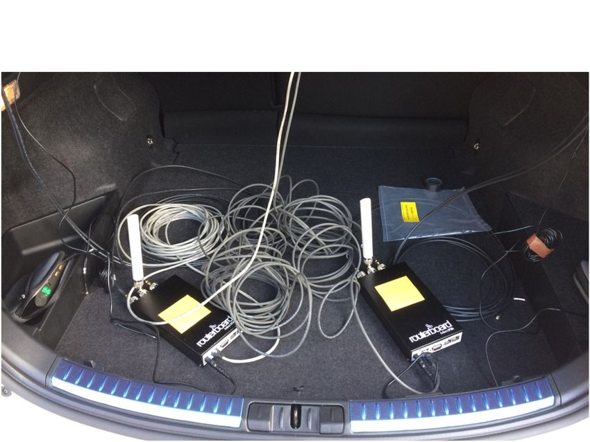
Internet/Cloud
                                    V2V
                                                               V2I
Logical Connection
Wireless Connection
                                                              V2V
 Wired Connection
   Fog Orchestrator               V2I
          DSRC RSU

                   Fog Area 1                      V2V
                                                                      Fog Area 2

      RSU Coverage region
                                                               Fog Area 3
      No Coverage region                     V2I

Fig. 1. A general overview of the considered system model. The C-ITS design frame-
work ensures V2X connectivity and a NFV architecture in the infrastructure domain.

2      Experimental Testbed Architecture

2.1     Description of the System Architecture

Our developed experimental VANET testbed consists of different devices and
entities. Each one will play a significant role in the operation of our system. An
ideal design paradigm can be found in Fig. 1. The different devices that will
form our system paradigm are the following:

 – Road Side Units (RSUs): Network infrastructure devices, mounted on sev-
   eral building, and connected to a centralised control plane to provide V2I
   connectivity.
 – On-Board Units (OBUs): Devices installed in the vehicles, able to exchange
   safety critical messages with the RSUs and other vehicles.
 – Fog Orchestrators (FOs): Devices that centrally manage the different clus-
   tered management areas, called Fog Areas, ideally with one-hop distance
   from the RSUs to reduce the end-to-end delay.

    As shown in Fig. 1 the RSUs and OBUs will be connected to each other
using IEEE 802.11p/DSRC links. In our system, vehicles can connect to another
vehicle (when driving at no coverage regions) or to RSUs (when within the
RSU coverage range). In our system paradigm, we assume that our infrastruc-
ture network is clustered in different management areas called Fog Areas. FOs
manage each Fog Area and share a wired connection with the different RSUs.
Being one-hop away from the RSUs, they can be used to process all the time-
critical information received or generated at the infrastructure side with reduced
end-to-end delay. Finally, our system will interact with a cloud-based city-wide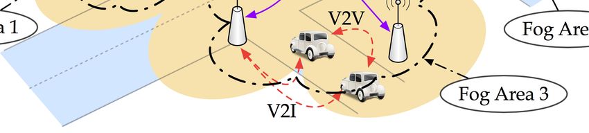
connection, interfacing with the different FOs. The cloud-based service will be
responsible for recording city-scale data, interconnecting the different FOs and
Fog Areas and pushing city-scale policies in the entire network. Some more de-
tails about this system architecture can be found in [16,20,17,18]. In the next
section, we will describe in greater detail the testbed components that we have
already designed and deployed around the City of Bristol. Compared to our
work in [15], in this work, we will focus more on the exchange of Cooperative
Awareness Messages (CAMs) on V2I and V2V links as well as the challenges
that we faced concerning the large-scale deployment and our solutions for them.
Our discussion on the current large-scale deployment will be followed by some
preliminary results from our experimental study. Finally, for our current work,
the idea of Fog Areas and the deployment of FOs was not considered. This will
be a task for our future research activities.
2.2 Description of the Experimental Setup
For our experimental validation, we prototyped an open-source IEEE 802.11p/DSRC
testbed (Fig. 2). Our devices, under ideal-like Line-of-Sight (LOS) conditions,
were able to achieve good performance and high Packet Delivery Rate (PDR)
for distances up to 700 m (as proven in [15]).
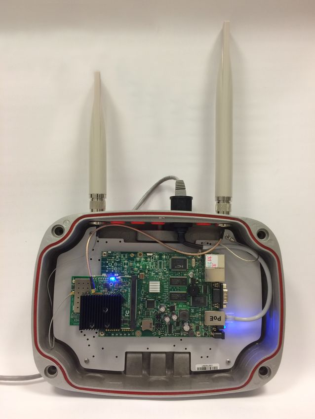
The devices were designed to be used as both RSUs and OBUs (Figs. 2a
and 2b). They were equipped with a Mikrotik RB433 single-board computer
(CPU 300 MHz, 64 MB RAM, 64 MB storage space, x3 Ethernets, x3 MiniPCI
slots) [4]. Also, two wireless IEEE 802.11a NICs were used for redundancy, one
regarded as High Power (HP) and the second one regarded as Low Power (LP).
The wireless interfaces of the RSUs and the OBUs in our system are accompanied
by different antennas as shown in Figs. 2a and 2c, one bolted on the RSUs and the
second magnetically attached to the roof of our vehicles. Our RSU devices were
powered up via Power-over-Ethernet (PoE), while a battery pack was used for
the OBUs to avoid the voltage spikes experienced when using a lighter inverter
within the vehicle. All the device and the key driver characteristics can be found
in Table 1.
OpenWRT1 , a low-latency Linux distribution, was used as the operating
system for both devices. Both drivers (Table 1) and the Linux kernel modules
were modified accordingly to enable IEEE 802.11p compatibility (Fig. 3). The
5.9 GHz band was added to the regulatory domain and the Outside the Context
of a BSS (OCB) mode was enabled in the MAC layer, to allow NICs to oper-
ate without being associated. The values for the contention windows and the
Modulation and Coding Rates (MCSs) were chosen to follow the regulation for
the ITS-G5 standard specification. Integration with a GPS dongle via a USB
interface was enabled. A beaconing interface was also developed that generates
IEEE 802.11p DSRC CAMs and broadcasts them in the network. More details
about the modifications can be found in [15].
1
OpenWRT Barrier Breaker Release no. 14.07 - https://openwrt.org/
High-gain Antenna
Low-gain Antenna
                                                              OBU Devices
                                            Battery Pack
                          Road-Side and
              High Power On-board Unit
Low Power     transceiver
transceiver

(a) IEEE 802.11p /
DSRC RSU units.                               (b) IEEE 802.11p / DSRC OBU units.

                                                    OBU Antenna

                              (c) OBU antenna mounted on the roof of the car.

Fig. 2. Our experimental setup. We prototyped both RSUs and OBUs units, equipped
them with different antennas and conducted our trials around the City of Bristol.

    The GPS coordinates, the speed, the heading and the timestamp of the GPS
are being encapsulated within the transmitted CAMs. A logging interface was
designed that logs all the packets generated, transmitted and received. An exam-
ple of the packets exchanged can be found in Fig. 4. At the TX side, the acquired
GPS coordinates are represented as GpsLongitude, GpsLatitude, being respec-
tively the longitude and latitude values. The InterLongitude and InterLatitude
values are the interpolated values based on the acquired GPS coordinates. The
SeqNum is the sequence number of the packet generated (starting at zero when
the device boots up). The GpsSpeed and InterSpeed are the acquired values from
the GPS dongle and the interpolated value respectively. Finally, the Timestamp
is the time that the packet is generated, given in Unix Epoch format. The rest
of the fields are used for debugging purposes only.
    At the RX side, the RxMAC is logged at first, which is the MAC address
of the device transmitted the packet. RxLongitude and RxLatitude are the GPS
coordinates encapsulated in the transmitted packet. Finally, the InterLongitude
LP-RSU                LP-OBU                   HP-RSU               HP-OBU
              Model             Mikrotik R52H [2]                              Mikrotik R5SHPn [3]
        TX Power                        25 dBm                                         29 dBm
    Antenna Gain               7 dBi                     5 dBi                9 dBi                5 dBi
     Linux Driver                         ath5k                                         ath9k
      Bandwidth                                                   10 MHz
        Frequency                      5.89 GHz                                        5.9 GHz
CWmin , CWmax                                                    [15, 1023]
               MCS                                               QPSK 1/2

               Table 1. Wireless Network Interface Controller Characteristics

                                Deadline I/O Scheduler
 Frame Generation                                            ieee80211_ops
                                                                              ath9k
                                            cfg80211_ops
                                                                              ath5k           Soft-MAC
                    nl80211
                                                                                              Hardware
                                   cfg80211              mac80211              …
Utilities - iw, …
                    Userspace                  Kernelspace                    Driver   Hardware

Fig. 3. Linux Kernel Modules modified to enable the IEEE 802.11p/DSRC capabilities
in our system.

and InterLatitude values represent the current longitude and latitude of the re-
ceiver, acquired from the GPS dongle and interpolated later. The remaining
values are similar to the transmitted packet. The above system is highly cus-
tomisable, and in the future, more features extracted from different sensors can
be encapsulated in the exchanged frames to introduce different vehicular appli-
cations and expand the cooperative awareness of a vehicle.

3     Field Trials and Preliminary Results

The testbed mentioned above was evaluated under a city-scale deployment dur-
ing three days of field trials. Throughout the entire evaluation process, we tested
various vehicular communication scenarios (both V2V and V2I) under various
conditions (urban, rural, highway). The idea behind these field trials was to
test the performance of our devices, identify the limitations of our system and
find ways to overcome them, and finally get a more in-depth understanding for
how a massive city-scale deployment should be approached in the future. In this
work, firstly we will investigate the Key Performance Indicators (KPIs) from the
perspective of the first car and the RSUs, while the second vehicle acts as an
interferer when being within coverage. Secondly, we will present a V2V scenario.
    Three RSUs were deployed at first at three locations around the City of
Bristol, UK (as shown in Fig 5a). Hydrogen-RSU was mounted at the height
Fig. 4. Example of the log file generated at the transmitter and the receiver side.

of around ˜8 m, on a curvy, narrow road very close to a blind T-junction. The
second one (Helium-RSU ) was installed on the wall of a building next to a
straight road with some foliage at the sides at ˜5 m. Finally, Lithium-RSU was
placed on the balcony of a tall building (at ˜25 m height), next to a wide road,
providing the most LOS coverage compared to the other RSUs. The different
locations and buildings were chosen to evaluate how the position of a RSU can
affect the performance of the network.
    Two vehicles (as in Fig. 2c), equipped with one OBU each, were driving
randomly around the city. The second OBU unit shown in Fig. 2b was there for
backup purposes only. All the devices in our system generated and transmitted a
CAM per NIC every 10 ms. Each CAM, encapsulating the information described
in Sec. 2.2, was logged at the transmitter and the receiver side. The log files
generated were used later to produce the results that will be described in the
next section.
    In the next section, we will present our preliminary results. We will focus our
performance investigation on some meaningful KPIs related to our research and
will try and comprehend the different advantages and drawbacks of our system
analysing our findings. Throughout the three days of field trials, we exchanged
˜50 million CAMs. Some of our results will use a subset of these exchanged
messages. Our entire dataset is available for download in [1]. To the best of our
knowledge is one the largest data repositories focused on V2X communications.

3.1   Preliminary Results

Firstly, we start with the V2I scenario. Fig. 5 presents the heatmap results for
the PDR from all CAMs transmitted from a RSU and received at the vehicle
side. The results present the PDR for the vehicle no. 1. Vehicle no. 2 acts as
an interferer, as mentioned before, when both vehicles are within the same RSU
coverage range. Finally, the red crosses, show the position of a vehicle when a
CAM broadcast was successfully received at the RSU side.
    Figs. 5a and 5b show the PDR results when both vehicles were driving within
the coverage regions of the RSUs. Figs. 5c and 5d show the results when only
vehicle no. 1 was within coverage. As described, the DSRC CAMs are being
broadcast from all NICs every 10 ms without having any coordination on the
channel usage. As shown, there is a significant PDR difference of 30% between
the different scenarios, for both the HP and LP transceivers. This is because,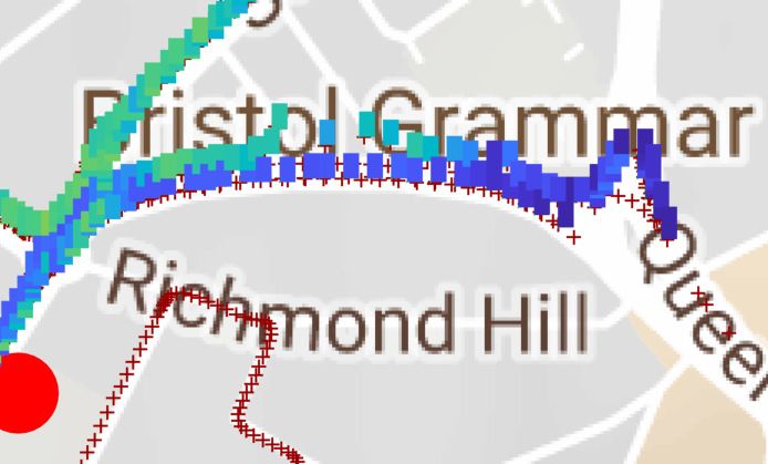
Helium-RSU

     Lithium-RSU

                                Hydrogen-RSU

(a) Both Vehicles within RSU coverage -        (b) Both Vehicles within RSU coverage -
HP transceiver.                                LP transceiver.

(c) Only Vehicle 1 within RSU coverage -       (d) Only Vehicle 1 within RSU coverage -
HP transceiver.                                LP transceiver.

       Fig. 5. Heatmap results for different V2I scenarios (HP and LP NICs).

the second vehicle, acting as an interferer, led to a big number of frame collisions
and longer MAC-layer contention intervals at the receiver side.
    The difference can be observed at the RSU side as well. As shown, the
heatmap data overlap with the red crosses in Figs 5c and 5d, while they do
not precisely match the heatmap in the first two figures. This means that when
the interfering vehicle was present, vehicle no. 1 was not always able to establish
a bidirectional communication link with the RSUs.
    In Fig. 6, we present the frequencies of the transmission interval between two
DSRC CAM. This is an example from Hydrogen-RSU for all CAMs transmitted
throughout one day of field trials. The remaining devices and days produced
similar results, therefore will not presented in this work. As shown, even though
the CAM transmission interval was set at 10 ms, our testbed generates frames
at a different rate. Most of the frames are generated and exchanged either every
12 ms or 14 ms. This was expected as our devices are built upon a single-core
CPU, which executes tasks with the same priority according to the Linux Dead-
line I/O Scheduler. To that extent, the CPU cannot fetch/push CAMs streams
towards the transceivers at a constant I/O rate. These inconsistencies should
be taken into account when designing vehicular applications with strict latency
requirements. Generating and processing the packets at a stronger Fog node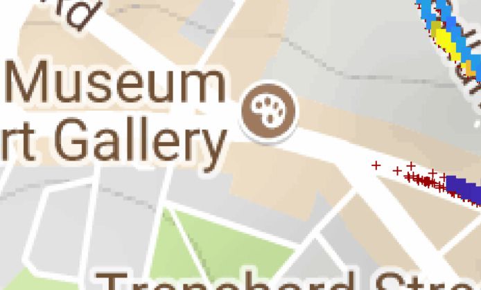
Fig. 6. Transmission Intervals between two DSRC CAMs.

         Fig. 7. Awareness Horizon for the V2V Scenario - HP transceiver.

computer, and using the transceivers as the medium to exchange the packets,
will significantly improve the consistency of the transmission rate.
    Finally, Fig. 7 presents the awareness horizon for the V2V scenario, i.e. the
Euclidean distance between the vehicles when a CAM is received. For this ex-
periment, two vehicles were driving at opposing directions on a highway section
of the road exchanging CAMs every time they were crossing paths. As shown
in Fig. 6 most packets are being transmitted every 12 ms or every 14 ms. Given
that the vehicles drive at a constant speed, we can estimate that a similar num-
ber of packets was exchanged at every distance interval. We observe that when
the vehicles are in close proximity, a bigger number of packets is being received
compared to longer distances. When the vehicles are more than 80 m apart, most
of the packets are never delivered. Similar performance can be observed in the
rural and urban trials conducted. From the above, we can observe that using the
previously described setup, we can achieve adequate V2V communications for
up to about 80 m. For sensor features exchange at longer distances, a multi-hop
communication using V2V or V2I links is necessary.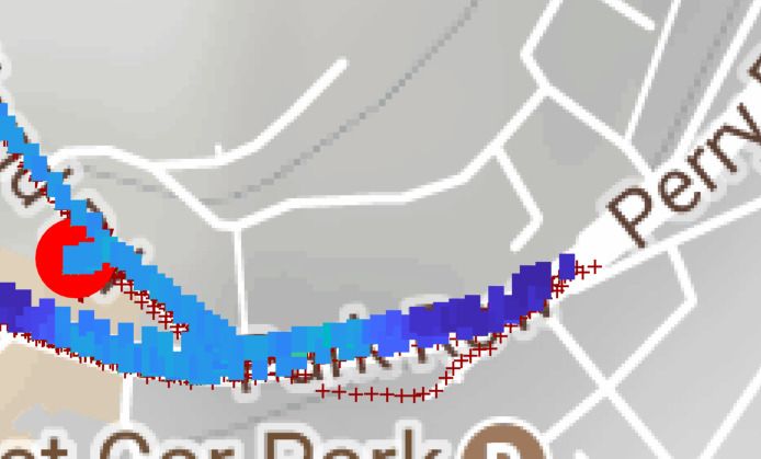
4   Conclusions and Future Work
In this work, we presented a city-scale ITS-G5 network for next-generation ITSs.
Our testbed can be used to test different networking protocols for CAVs. Utilising
COTS devices can be costly and risky as their performance may be inadequate.
Therefore, prototyping our testbed, we managed to reduce the deployment cost
and get an in-depth understanding of the requirements and limitations of real-
world large-scale deployments. The customisability and the open-source nature of
our testbed are of paramount importance as different parameters can be tweaked
to enhance the performance of the system and address any drawbacks.
    Conducting some initial field trials, we observed the behaviour of our deploy-
ment under different conditions and scenarios. Some critical observations can be
the inconsistency at the data generation, proving the necessity for a Fog comput-
ing implementation and the real-world performance evaluation that proves the
need for more sophisticated MAC-layer access schemes and a centralised control
plane. Our dataset of the exchanged CAMs can be downloaded from [1]. In the
future, we intend to expand the deployed locations of our testbed, to provide
almost-city-scale availability for vehicular applications. What is more, we will
integrate SDN-like and Fog computing capabilities with our system to enhance
its performance and scalability. Finally, a cybersecurity framework [19] will be
introduced on top of our design, to secure the V2V and V2I links for potential
malicious threats.

Acknowledgements
This work was partially supported by the University of Bristol and the Engineer-
ing and Physical Sciences Research Council (EPSRC) (grant EP/I028153/1). It
is also supported in part by the Innovate UK FLOURISH project under Grant
no. 102582.

References
 1. FLOURISH Car Trials - Dataset of three days of field trials. https://seis.
    bristol.ac.uk/~eerjp/v2xtrials/, accessed: 04-07-2018
 2. Mikrotik R52H Data Sheet, https://mikrotik.com/product/R52H
 3. Mikrotik R5SHPn Data Sheet, https://routerboard.com/R5SHPn
 4. Mikrotik RB433 Data Sheet, https://mikrotik.com/product/RB433
 5. IEEE Standard for Wireless LAN Medium Access Control (MAC) and
    Physical Layer (PHY) Specifications - Amendment 6: Wireless Ac-
    cess in Vehicular Environments. IEEE Std. 802.11p-2010 (Jul 2010).
    https://doi.org/10.1109/IEEESTD.2010.5514475
 6. IEEE Standard for Wireless Access in Vehicular Environments (WAVE)
    - Multi-Channel Operation. IEEE Std. 1609.4-2016 pp. 1–94 (Mar 2016).
    https://doi.org/10.1109/IEEESTD.2016.7435228
 7. IEEE Standard for Wireless Access in Vehicular Environments (WAVE)
    - Networking Services. IEEE Std. 1609.3-2016 pp. 1–160 (Apr 2016).
    https://doi.org/10.1109/IEEESTD.2016.7458115
8. Ameixieira, C., Cardote, A., Neves, F., Meireles, R., Sargento, S., Coelho, L.,
Afonso, J., Areias, B., Mota, E., Costa, R., Matos, R., Barros, J.: Harbornet: a
real-world testbed for vehicular networks. IEEE Communications Magazine 52(9),
108–114 (Sep 2014). https://doi.org/10.1109/MCOM.2014.6894460
9. Demestichas, P., Georgakopoulos, A., Tsagkaris, K., Kotrotsos, S.: Intelligent 5G
Networks: Managing 5G Wireless/Mobile Broadband. IEEE Veh. Technol. Mag.
10(3), 41–50 (Sep 2015). https://doi.org/10.1109/MVT.2015.2446419
10. Eriksson, J., Balakrishnan, H., Madden, S.: Cabernet: Vehicular Content Deliv-
ery Using WiFi. In: Proc. of the 14th ACM International Conference on Mobile
Computing and Networking. pp. 199–210. MobiCom ’08, ACM, New York, NY,
USA (2008). https://doi.org/10.1145/1409944.1409968, http://doi.acm.org/10.
1145/1409944.1409968
11. Fantacci, R., Tarchi, D., Tassi, A.: A Novel Routing Algorithm for
Mobile Pervasive Computing. In: Proc. of IEEE 2010 (Dec 2010).
https://doi.org/10.1109/GLOCOM.2010.5683765
12. Fazio, P., Rango, F.D., Sottile, C.: A Predictive Cross-Layered Interference
Management in a Multichannel MAC with Reactive Routing in VANET.
IEEE Transactions on Mobile Computing 15(8), 1850–1862 (Aug 2016).
https://doi.org/10.1109/TMC.2015.2465384
13. Hull, B., Bychkovsky, V., Zhang, Y., Chen, K., Goraczko, M., Miu, A.K., Shih, E.,
Balakrishnan, H., Madden, S.: CarTel: A Distributed Mobile Sensor Computing
System. In: Proc. of 4th ACM SenSys. Boulder, CO (Nov 2006)
14. Levinson, J., Askeland, J., Becker, J., Dolson, J., Held, D., Kammel, S., Kolter,
J.Z., Langer, D., Pink, O., Pratt, V., Sokolsky, M., Stanek, G., Stavens, D., Te-
ichman, A., Werling, M., Thrun, S.: Towards Fully Autonomous Driving: Sys-
tems and Algorithms. In: IEEE Intel. Veh. Symp. IV. pp. 163–168 (Jun 2011).
https://doi.org/10.1109/IVS.2011.5940562
15. Mavromatis, I., Tassi, A., Piechocki, R.J., Nix, A.: Agile Calibration Process of
Full-stack Simulation Frameworks for V2X Communications. In: Proc. of IEEE
VNC 2017. pp. 89–96 (Nov 2017). https://doi.org/10.1109/VNC.2017.8275604
16. Mavromatis, I., Tassi, A., Rigazzi, G., Piechocki, R.J., Nix, A.: Multi-Radio 5G
Architecture for Connected and Autonomous Vehicles: Application and Design
Insights. EAI Transactions on Industrial Networks and Intelligent Systems (Jan
2018). https://doi.org/10.4108/eai.20-3-2018.154368
17. Mavromatis, I., Tassi, A., Piechocki, R.J., Nix, A.: MmWave System for Future
ITS: A MAC-layer Approach for V2X Beam Steering. In: Proc. of IEEE VTC-Fall
2017 (Sep 2017). https://doi.org/10.1109/VTCFall.2017.8288267
18. Mavromatis, I., Tassi, A., Piechocki, R.J., Nix, A.: Efficient V2V Communication
Scheme for 5G MmWave Hyper-Connected CAVs. In: Proc. of IEEE ICC 2018
(May 2018)
19. Rigazzi, G., Tassi, A., Piechocki, R.J., Tryfonas, T., Nix, A.: Optimized Certificate
Revocation List Distribution for Secure V2X Communications. In: Proc. of IEEE
VTC-Fall 2017 (Sep 2017). https://doi.org/10.1109/VTCFall.2017.8288287
20. Tassi, A., Egan, M., Piechocki, R.J., Nix, A.: Modeling and Design
of Millimeter-Wave Networks for Highway Vehicular Communication. IEEE
Transactions on Vehicular Technology 66(12), 10676–10691 (Dec 2017).
https://doi.org/10.1109/TVT.2017.2734684
21. Tong, Z., Lu, H., Haenggi, M., Poellabauer, C.: A Stochastic Geometry Ap-
proach to the Modeling of DSRC for Vehicular Safety Communication. IEEE
Transactions on Intelligent Transportation Systems 17(5), 1448–1458 (May 2016).
https://doi.org/10.1109/TITS.2015.250793922. Walker, J.: The Self-Driving Car Timeline Predictions from
the Top 11 Global Automakers. https://www.techemergence.com/
self-driving-car-timeline-themselves-top-11-automakers/, Online; Ac-
cessed on: 27-03-2018You can also read