A Cost-Effective Pulse Oximeter Designed in Response to the COVID-19 Pandemic
←
→
Page content transcription
If your browser does not render page correctly, please read the page content below
A Cost-Effective Pulse
Oximeter Designed in
Response to the COVID-19
                                                                                           HARDWARE
Pandemic                                                                                   METAPAPER

BENJAMIN METCALFE
PEJMAN IRAVANI
JONATHAN GRAHAM-HARPER-CATER
RICHARD BOWMAN
JULIAN STIRLING
PETER WILSON
*Author affiliations can be found in the back matter of this article

ABSTRACT                                                                                   CORRESPONDING AUTHOR:
                                                                                           Peter Wilson
This paper introduces the design of a small and cost-effective optical pulse oximeter,
                                                                                           Department of Electronic
including a finger clip, sensor readout electronics, and associated firmware. The device   and Electrical Engineering,
is based on widely-available commercial optical sensors that are designed for the          University of Bath, GB
wearables market and measure the reflection of different wavelengths of light. This        p.r.wilson@bath.ac.uk
design was produced in response to a request from the Royal United Hospital in Bath
UK, in light of the severe shortage of clinical pulse oximeters during the 2020 COVID-19
pandemic. Products based on this design have not been submitted for medical device
                                                                                           KEYWORDS:
approval; the design documents here should be considered purely for research,              pulse oximetry; optical
educational and development purposes.                                                      measurement; medical
                                                                                           devices

                                                                                           TO CITE THIS ARTICLE:
                                                                                           Metcalfe, B, Iravani, P,
                                                                                           Graham-Harper-Cater, J,
                                                                                           Bowman, R, Stirling, J and
                                                                                           Wilson, P. 2021. A Cost-
                                                                                           Effective Pulse Oximeter
                                                                                           Designed in Response to the
                                                                                           COVID-19 Pandemic. Journal
                                                                                           of Open Hardware, 5(1): 1,
                                                                                           pp. 1–11. DOI: https://doi.
                                                                                           org/10.5334/joh.26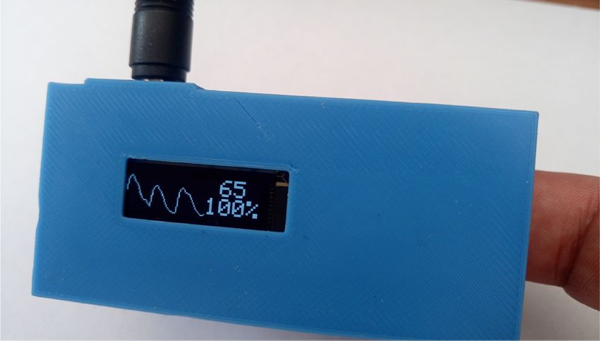
METADATA OVERVIEW                                                                                     Metcalfe et al.
                                                                                                      Journal of Open Hardware
                                                                                                                                 2

                                                                                                      DOI: 10.5334/joh.26
•   Main design files: https://gitlab.com/openoximeter/, in particular the Electronics, MAX3010x
    Breakout Board, Firmware, and Finger Clip repositories.

•   Target group: medical device developers, biomedical engineers

•   Skills required: Arduino – intermediate, electronics – intermediate, 3D printing – easy;

•   Replication: This was developed by a team working remotely and has been replicated
    by different members of the team, and has also been replicated by reviewers of the
    manuscript and colleagues at other institutions.

•   See section “Build Details” for more detail.

HARDWARE OVERVIEW
INTRODUCTION
The worldwide COVID-19 pandemic produced an unprecedented strain on the resources of
many healthcare systems. Within England that strain was felt most acutely within the Accident
and Emergency (A&E) wards that continue to deal with rapid triage and admissions of many
patients. A key component of triage has been the monitoring of a patient’s Saturated Percentage
of Oxygen (SpO2), particularly with reference to respiratory conditions. The SpO2 metric has been
heavily used in both the triage and the prognostication of patients with suspected COVID-19.
As the numbers of cases increased dramatically around the world the pressure on healthcare
providers at both the national and international level became almost unmanageable. The need
for point of care monitoring of SpO2 for large numbers of patients led directly to both a supply
shortage and a cost increase of commercial sensors.

A request was therefore made by the Royal United Hospital (RUH) in Bath, England, to the Faculty
of Engineering and Design at the University of Bath to design and manufacture indicative SpO2
sensors that might be used to triage patients upon arrival at the hospital. Thus, this paper
describes the design and implementation of such a device, which can be produced using a
3D-printer without the need for specialist electronics assembly tools and at a reasonable cost.

The NHS has recently produced guidance about the usage of pulse oximetry to detect early
deterioration of patients with COVID-19 [1]. This includes the usage of pulse oximeters at
home, potentially requiring larger numbers of devices to be available.

IMPLEMENTATION AND DESIGN
Pulse Oximetry
The pulse oximeter is a device for non-invasive, continuous measurement of oxygen saturation
within arterial blood. A pulse oximeter uses two separate technologies in order to achieve
this: photoplethymography where reproduction of the pulsatile component takes place, and
spectroscopy where absorption of light of specific wavelengths by tissues takes place. Pulse
oximeters use light-emitting diodes (LEDs) to emit two different wavelengths of light, usually
660nm (red) and 940nm (infrared) in order to compare the absorption specta of oxyhaemoglobin
(HbO2) and deoxyhaemoglobin (H Hb). Figure 1 shows the absorbtion spectra, in the range
red to infrared, of both H Hb and HbO2 [2, 3]. It can be seen that at 600nm deoxygenated
haemoglobin (H Hb) absorbs more light than oxygenated haemoglobin (HbO2), while at 940nm
the inverse is true. Pulse oximeters may operate in either a transmission or reflection mode,
whereby the absorption characteristics are measured by either the amount of light transmitted
through the tissue or the amount of light reflected back by the tissue.

The oximeter alternately switches between emitting and measuring light at the two different
wavelengths at a rate of about 400 Hz. Absorption of red and infrared light in the tissue of
the finger is not confined to arterial blood but will also occur within the nail, muscle, fat, and
venous blood. However, the absorption from these “off target” tissues is relatively constant (DC),
whereas absorption within the arterial blood is pulsatile (AC) in response to changes in blood
pressure during the cardiac cycle. Thus, the role of the oximeter processing system is to eliminate
the DC component and to measure the ratio of light absorption between the pulsatile (AC) red
and infrared components. The inset in Figure 2 illustrates graphically the AC and DC signals.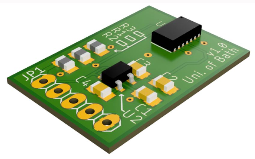
Metcalfe et al.               3
                                                                                                    Journal of Open Hardware
                        101                                                 Oxyhaemoglobin          DOI: 10.5334/joh.26
                                                                            Deoxyhaemoglobin
 Absorbtion (cm-1/mM)

                        100

                                                                                                    Figure 1 The absorption
                                                                                                    spectra for oxyhaemoglobin
                                                                                                    and deoxyhaemoglobin over
                          600   660         700         800        940       Wavelength (nm)        thee range 600 nm to 1000
                                                                                                    nm. Note that the y axis is
                                Red                              Infrared
                                                                                                    logarithmic.

                                                                                      AC660
                                                        Signal

                        100

                         85                                                           DC660

                                                                 Time
     %SpO2

                                                                                                    Figure 2 Typical calibration
                         16
                                                                                                    curve relating the R ratio
                                             R = AC660/DC660                                        the SpO2, note that for R = 1
                                                 AC940/DC940                                        SpO2 = 85%. Inset: example
                                                                                                    received signal for a 660 nm
                                                                                                    wavelength demonstrating
                                                                                                    the pulsatile AC component
                                      1.0              2.0       3.0            3.5                 and the DC component caused
                                                                                                    by absorption in other tissues
                                                          R
                                                                                                    such as the nail and bone.

Mathematically this ratio, R is defined as:

                                                       AC660 / DC660
                                                  R=                 (1)
                                                       AC940 / DC940

An empirical calibration curve (based on data measured using simultaneous blood gas analysis)
is then used to convert the R ratio to an SpO2 value. Figure 2 shows a typical calibration curve,
note that for R = 1 SpO2 = 85% [2, 3]. The final reading is usually a time average of commonly
10 to 20 seconds. Simultaneously, a peak detection algorithm can measure the time between
each successive peak in either of the AC components in order to measure the heart rate. Errors
in the reading are common, and can stem from movement artefacts, ambient light, occlusion
of the pulsatile component by clamping force, nail polish, and any number of physiological
conditions such as hypertension or vasoconstriction. Despite the numerous sources of error,
pulse oximetry remains an invaluable, and generally reliable, measure of saturated oxygen
content.

System Architecture
The system is designed to measure both heart rate and saturated oxygen content using
dual-wavelength photoplethysmography. The optical sensors are from the MAXIM range of
integrated circuits (MAX30100, 30101, or 30102) [4, 5, 6] and include all the required drive
and sense electronics. Data is transferred from the optical sensor to an Arduino Nano, which
computes a time averaged heart rate and SpO2 for display on an OLED screen based on the SSD
1306 OLED driver.

An architectural plan of the system is shown in Figure 3.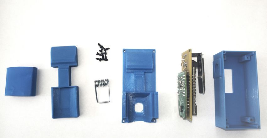
Metcalfe et al.            4
                                                                                                     Journal of Open Hardware
                                                                                                     DOI: 10.5334/joh.26

                                                                                                     Figure 3 Electronics
                                                                                                     architecture.

Design Methodology
Given the unique circumstances of the COVID-19 pandemic, and the lockdown restrictions
placed on the design team, it is useful to describe the design environment and design process.
The team members were all working at separate locations (at home) with varying levels of
capability to undertake manufacture and testing of the devices. Some of the team had access to
3D printers, some to solder stations for electronics assembly and some had access to software
design tools for printed circuit board design, software development and 3D CAD modelling.

One of the main challenges was to coordinate the efforts of the team members and to enable
both independent manufacture and test of the devices. At the time of writing it should be
noted that the team members have yet to all meet in person, and therefore it is remarkable
that a batch of completed monitors have already been delivered to the RUH.

Initial development was performed using breakout boards and breadboards. The MAX3010x
breakout boards were available in limited quantities, and were sufficient to build approximately
20 devices without the need for custom PCBs. Once the team expanded to include 3D printing
and device design expertise a fully custom PCB and finger clip were designed.

The team made extensive use of open source or freely available design tools wherever possible.
Eagle was used for PCB design, Inventor, FreeCAD and OpenSCAD were used for CAD design,
with the final designs being implemented in FreeCAD and OpenSCAD using scripts to enable
easy customisation of the design modules.

The decision to use the Arduino platform was based on the concept of simplicity. The Arduino
nano has a small footprint, contains on board power management, and hardware I2C interfaces
required for communication with display and sensor. While it would have been eminently
possible to develop boards using the ATMega328P microprocessor used on the Arduino boards,
the cost and time constraints made this an unattractive option for this project.

The team worked using online repositories to share information and manage the design data,
first using Microsoft Teams and then migrating to the gitlab online repository system. Microsoft
teams was used for conference calls, design discussions and engagement with clinical experts
or engineering specialists where required. Three distinct sites were set up with the capability to
3D print devices and assemble electronics to enable validation of the manufacture process and
independent assembly and testing.

Finally, trial devices were delivered to a contact in the RUH for testing and results shared back
electronically to the team for further analysis and development.

It is also important to stress the urgency that was placed on the project. The RUH were
predicting that their intrinsic capacity for monitoring SpO2 would be overwhelmed within 14–21
days of the project starting.

Electronics
The electronics consisted of three main components, an Arduino Nano microprocessor, a
MAX3010x pulse oximeter breakout board, and an SSD1306 based display. The electronic
components were connected as shown in Figure 3. An external power source was provided by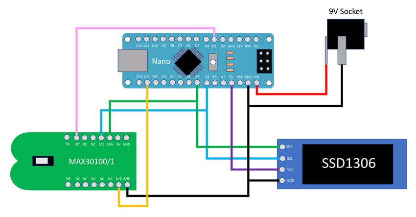
a PP3 9V battery chosen due to high power density and low cost. A simple PCB interposer was        Metcalfe et al.               5
                                                                                                   Journal of Open Hardware
implemented to connect the three main components and to reduce the assembly time to a              DOI: 10.5334/joh.26
few minutes.

Various options for powering the device were considered including integrating a small battery,
such as a coin cell, AA, AAA or pp3 9V battery, or using an external power source. One of
the disadvantages of a fully integrated battery was that in a clinical setting there would be
the need for frequent replacement of the battery. This would therefore require a procedure
of repeated disassembly, cleaning, and reassembly prior to redeployment with a patient. The
decision was taken therefore to use an external power source. The external power source could
be either a battery or DC supply from an external power supply. This also had the potential
advantage of being able to be powered perpetually using a small mains powered charger in a
hospital setting, or using an off the shelf, readily available battery holder. Both options were
designed to plug into the pulse oximeter hardware using a standard 9V plug, making it an easy
and rapid battery replacement (with no need for removal of battery cover perhaps requiring
specialist tools such as a screwdriver) or switching between a AC mains supplied charger and
external battery pack of the patient was required to be moved.

Initially the design was implemented using a commercially available MAX3010x pulse
oximeter breakout board, however, unfortunately, a global shortage of MAX3010x breakout
boards meant that it was necessary to design an alternative that could be manufactured if
required. This board, shown in Figure 4, was designed to utilise the same header and pin layout
as the commercial breakout boards. Multiple suppliers were contacted and found to have large
stock levels of the base parts. This design, combined with the teams readily available board
assembly facilities, was therefore deemed reasonable mitigation in event of commercial board
shortage.

                                                                                                   Figure 4 MAX3010x breakout
                                                                                                   board, developed as a drop-
                                                                                                   in replacement in case of
                                                                                                   commercial breakout board
                                                                                                   supply shortage.

The PCB design of the interposer, the MAX3010x breakout board, and the assembly sequence
are given in the electronics repository contained in the following link:

https://gitlab.com/openoximeter/Electronics

Firmware
The firmware runs directly on the Arduino Nano and consists of four main components: Top-
level main file, MAX3010x library, SSD1306 library, and a beat detection and processing library.

The flow diagram for the top-level main file is shown in Figure 5. This file handles the overall
operation of the pulse oximeter, utilising separate hardware libraries and operation specific
classes and functions where appropriate. This modular approach ensured that the design
team were able to easily reuse elements of the firmware if any hardware elements changed
due to supply issues. This code built upon the work by the tinyPulsePPG project [7] and the
Arduino-MAX30100 project [8] combining and enhancing best practices and techniques found
in each.
Metcalfe et al. 6
Read Available Update Display Journal of Open Hardware
Flash Display
Raw Values (every 50ms) DOI: 10.5334/joh.26
Start Yes
No Figure 5 Flow diagram for
Finger SPO2 <
Present? Threshold? the top-level Arduino loop.
No
It should be noted that the
Yes display update time of 50
ms delay is non-blocking,
meaning that the code could
DC & Moving Calculate Apply Rolling
Beat Detection continue without freezing on
Average Filters BPM & SPO2 Average
this element.
Most existing oximeter projects utilised hardware specific libraries for their sensors. This was not
suitable for this application as supply chains were unreliable, making part sourcing challenging.
It was therefore decided that a generic MAX3010x library should be developed, supporting any
of the MAX3010x family of oximeter sensors. Development of a system for dynamic detection
of the sensors model was not a practical use of time or on-board memory, so a single define
statement was utilised at the top of the library header file to ensure that correct memory
mapping was achieved with minimal redundant compiled code. Future iterations of this work
could explore dynamic chip detection, allowing removal of this define statement and making
this generic library fully plug-and-play.
The official Adafruit SSD1306 library [9] was found to be both too large and too slow for
this application, causing a violation of the oximeter sensor’s relatively high minimum read
frequency requirements. As a result the light-weight and reduced SSD1306 library used in the
tinyPulsePPG project was adapted to provide the desired functionality. This new library proved
significantly faster and smaller than the Adafruit library, resulting in a significantly more stable
SpO2 reading.
An advanced beat detection class was developed, combining the light-weight moving average
and DC filters of the tinyPulsePPG project with the reliable and parametrised beat detector
state machine logic of the Arduino-MAX30100 project. This hybrid code was found to produce
a more accurate and stable measure of both the heart-rate and SPO2 values, while the
parametrisation allowed rapid calibration and tuning of the detection logic against commercial
devices.
The firmware was designed to boot into an operational mode (shown in Figure 6) without any
input from the user, ensuring that it was fast and practical to use in a hospital environment. If
the patients SPO2 levels were detected to have dropped below 95%, the firmware flashes the
screen at 2 Hz to draw the attention of medical staff. The patient would then be fitted with a
commercial and medically approved pulse oximeter to confirm their SPO2 levels. The firmware
developed for this project is available from:
https://gitlab.com/openoximeter/arduinocode
Figure 6 Example of the finger
clip display when operational.Finger Clip Metcalfe et al. 7
Journal of Open Hardware
The finger clip was constructed using conventional 3D printing in such a way that the electronics DOI: 10.5334/joh.26
described in the Electronics section above could be easily integrated. Each of the individual
finger clip elements (apart from the metal spring and screws) were designed for rapid printing,
with an allowance for the variety of finger sizes across different patients.
The 3D printed parts were designed to be printed using standard PLA or ABS plastic, with
standard settings on a commercially available 3D printer. The clip was tested with a number of
different printers including an Ultimaker 2+ and the RepRap-based [10] Prusa i3 Mk3S.
The clip was split into three main components to be 3D printed: Top Finger Clip – to apply
pressure to the finger, Base Plate – to hold the clip and have a window for the sensor, and a
box for the electronics. The printed components use approximately 25 g of PLA filament and
take fewer than 4 hours to print. Figure 7 illustrates each component and the overall assembly.
Self-tapping
screws Electronics
Top clip Bottom clip Box
Heat shrink
(optional) Spring
Figure 7 a) Finger clip
components prior to Assembly.
b) An exploded render of the
assembly. c) A render of the
assembled finger clip.
During the design process, various options for the implementation were reviewed including
using an external box for all the electronics and power apart from the sensor itself. While
this has some advantages, as it decreases the weight on the finger, it adds complexity to the
electronic assembly by requiring customised cabling and robust connectors. However, as the
finger clip and electronic assembly is sufficiently light (∼~55 g) this was not deemed necessary.
The finger clip was designed with a curved surface for the finger and the curvature designed
to accommodate a number of different finger sizes. The top part of the clip was designed such
that a piece of soft 3/4" tubing (such as heat shrink tubing) can be used to provide cushioned
support for smaller fingers. The test piece was designed for an adult finger size, however one
of the advantages of the modular design is that this single piece of the design could easily be
replaced to a different size such as children or small adults.
The base plate was designed with a holder for the spring clip, the base of the plate curves
smoothly down to a window for for the sensor. The filleted window has approximately 2.5 mm
clearance from the sensor on all sides, and the top of the sensor sits approximately 0.5 mm
above the base of the clip. This allows the pad of the finger to protrude slightly through the
window maintaining a firm, but comfortably supported, contact with the sensor. An indent on
the underside of the base was designed to fit the electronic surface mount components so that
the base and oximeter PCB maintain a flush fitting. This indent is not cantilevered and prints
well in PLA if the layer height is 0.2 mm or below, though may require support if printed in ABS.The electronics box was designed with internal pillars to locate the electronics assembly at the Metcalfe et al. 8
Journal of Open Hardware
correct height for the sensor to fit into the base plate window and for the display to fit correctly DOI: 10.5334/joh.26
in the display window. A side hole was placed to allow the external power source to be plugged
in using a barrel type 2.5 mm connector.
One key aspect of the system is ease of cleaning, although for large scale production the
compatibility of the printed components with standard hospital cleaning procedures would
need to be considered.
Prior Art
There have been several Open Source projects that have developed pulse oximeters based on
a similar architecture and with related goals to the work presented in this manuscript. They are
all based on the Arduino micro-processor but differ in the optical sensor used and in the overall
functionality. The GliaX/mechloud Oximeter [11, 12] uses a simple photodiode circuit with
two different light sources to perform the measurement, and an Adafruit SSD1306 display to
communicate the resulting measurements in text form. The xcoder123 Oximeter [13, 14] uses
a MAX30100 integrated sensor but does not include a visual display (data is communicated via
serial). Neither of these projects have seen any updates in the past 4 years.
More recently an Open Source Pulse Oximeter for COVID-19 was reported [15]. This is based on
the MAX30102 integrated sensor and uses an OLED screen for displaying data. This design also
included a finger-clip and was focussed on the COVID-19 pandemic. When compared to the
prior art, the work presented in this manuscript has a number of specific advantages.
• The pulsatile waveform is displayed on the screen in real time, which provides a good
visual indicator of the measurement reliability.
• The alarm feature alerts clinicians to a dangerous drop in the SpO2 level.
• The software libraries developed support the entire range of integrated MAX devices,
enabling deployment even with hardware shortages.
Testing and Feedback
Assembled devices were tested by both members of the design team and by clinicians at
the RUH. Fundamentally, calibration and validation of pulse oximeters over a wide range of
SpO2 values remains a challenging task. The best reference values are typically obtained via
an arterial blood gas analysis, but these are spot samples and simultaneous comparison to
measurements taken from a peripheral pulse oximeter is not trivial. Ideally an oximeter would
be calibrated across a wide range of SpO2 values, but this is also problematic. It is possible to
use environmental chambers to lower the SpO2 in a healthy person, but values much below
80% begin to lead to mental impairment and those below 75% to loss of consciousness [2].
Thus it becomes both technically and ethically problematic to obtain reference measurements
at lower levels of saturation.
In this project a simple set of comparative tests were performed against a number of commercial
pulse oximeters, mainly within the clinical environment. The design described in this paper
performed strongly in terms of heart rate estimation but consistently under-estimated the
SpO2 when reference values were below 98%. These correspond to the ranges that are hard to
obtain in a healthy person without an environmental chamber. Formal calibration is beyond the
scope of this work, but this work has highlighted the need for a phantom or other model that
can be used for the development and calibration of pulse oximeters.
General feedback from the clinicians was positive, the devices were tolerated well by patients
and proved to be both reliable and easy to clean. The main request for improvement was that
the oximeters be remotely linked, so that low SpO2 alarms could be observed centrally. This
could be readily integrated in future designs.
Future work
As presented here, the system represents a working pulse oximeter, capable of displaying
and recording SpO2 and Heart Rate. It is not certified for clinical use, and we expect that the
tolerances on critical components, particularly the optical sensor, will be looser than thoseon components supplied under contract to medical device manufacturers. However, as an Metcalfe et al. 9
Journal of Open Hardware
indicative point of care device for rapid triage it is fit for purpose. Future work is therefore to DOI: 10.5334/joh.26
develop robust calibration methods to characterise the sensor (in particular the wavelengths
of the LEDs) and realistic but easy to use “phantom” fingers that enable repeatable testing of
devices. Networking devices via Bluetooth to mobile phone applications is also of interest as
basic statistical analysis could be performed including the capability of uploading information
on-line for further clinical analysis.
CONCLUSION
This paper introduces the design of an open source and low cost pulse oximeter that can
be easily assembled with minimal tooling. It uses widely available components to provide
indicative measurements of SpO2 and Heart Rate that have been used for triage purposes
during the COVID-19 crisis. The design is not certified for use as a medical device, but is instead
a robust and flexible platform for the future development of sensors based on the MAX3010x
suite of optical sensors. The software libraries developed have been optimised for size and
speed, and have been adapted so that any of the MAX3010x sensors can be used with no code
changes.
QUALITY CONTROL
This design is not a certified medical device, and should not be used for monitoring of patients
in a clinical setting.
Characterising the wavelength of the LEDs and their relative intensity is important; we plan to
create hardware and software to facilitate this in the future.
It is important that the clip is sufficiently tight to stay attached to the patient’s finger for the
duration of monitoring, but not so tight as to affect the circulation. This can be approximately
tested by attaching it to a finger for 30 minutes and noting any discomfort or unusual readings.
The design is based on clothes pegs purchased from a supermarket in the UK, but has parametric
hole locations to allow adjustment of the clip tension by changing the angle through which the
spring is stretched.
APPLICATION
This sensor is intended to monitor the saturated oxygen content in a patient’s bloodstream,
and their heart rate. The design is not suitable for clinical applications and should be considered
an educational design, shared to provide a functional project that can be further developed by
the community.
BUILD DETAILS
AVAILABILITY OF MATERIALS AND METHODS
We have selected components for ease of availability – the MAX3010x optical sensor is stocked
by most major electronics suppliers, and other electronic parts are widely available. 3D printing
is used for all mechanical parts, except screws and the spring, which is taken from a clothes
peg.
EASE OF BUILD
Mechanical assembly should take less than one hour for someone familiar with basic assembly
tasks. Assembling the breakout board requires surface mount soldering. Alternatively, a
motherboard was developed to support the interfacing of existing MAX3010x breakout boards
with an Arduino nano and display. This motherboard requires only through-hole soldering
and uses the Arduino board to reduce the number of components required during assembly.
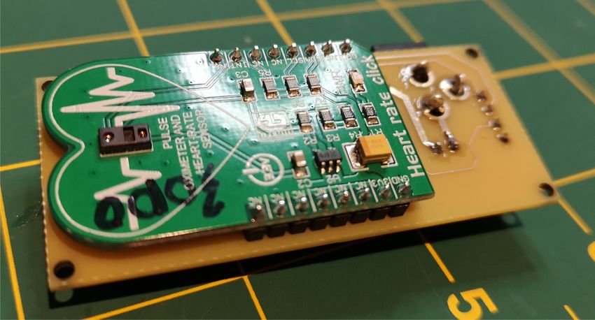
Figure 8 depicts this motherboard with the sensor breakout board fitted. Whichever hardware
option is selected, firmware can be uploaded using the Arduino IDE.Metcalfe et al. 10
Journal of Open Hardware
DOI: 10.5334/joh.26
Figure 8 A motherboard was
developed to allow connection
of existing MAX3010x
breakout boards with an
Arduino Nano and display. This
board utilises through-hole
assembly to make the build
process possible with minimal
equipment requirements. The
Arduino and display fit to the
OPERATING SOFTWARE rear side of the system.
The monitor is self-contained, and displays the readings on a small screen. Firmware resides in
the “Arduino Code” repository.
DEPENDENCIES
There are no dependencies.
HARDWARE DOCUMENTATION AND FILES LOCATION
Archive for hardware documentation, and editable design files
Name OpenOximeter Organisation on GitLab
Electronics https://gitlab.com/openoximeter/Electronics
Sensor breakout board https://gitlab.com/openoximeter/max3010x-breakout-board
Finger clip and enclosure https://gitlab.com/openoximeter/springfingerclip
Motherboard assembly instructions https://openoximeter.gitlab.io/Electronics/
License CERN Open Hardware License v2, Strongly Reciprocal (CERN-OHL-S)
Publisher University of Bath
Date Published 24/4/2020
SOFTWARE CODE REPOSITORY
Name OpenOximeter Organisation on GitLab
Arduino code https://gitlab.com/openoximeter/arduinocode
License GNU GPL v3
Publisher University of Bath
Date Published 24/4/2020
DATA AVAILABILITY STATEMENT
Data, code, and hardware designs referenced in this manuscript are available from our repositories.
FUNDING INFORMATION
We would like to acknowledge financial support from EPSRC (EP/P029426/1, EP/R013969/1),
the University of Bath Alumni Fund, the Faculty of Engineering and Design at the University of
Bath, and the Royal Society (URF\R1\180153).
COMPETING INTERESTS
The authors have no competing interests to declare.AUTHOR CONTRIBUTIONS Metcalfe et al.
Journal of Open Hardware
11
DOI: 10.5334/joh.26
All authors contributed to discussions and writing of the manuscript.
AUTHOR AFFILIATIONS
Benjamin Metcalfe orcid.org/0000-0003-4279-8930
Department of Electronic and Electrical Engineering, University of Bath, GB
Pejman Iravani orcid.org/0000-0002-4965-0341
Department of Mechanical Engineering, University of Bath, GB
Jonathan Graham-Harper-Cater orcid.org/0000-0001-9628-4789
Department of Electronic and Electrical Engineering, University of Bath, GB
Richard Bowman orcid.org/0000-0002-1531-8199
Department of Physics, University of Bath, GB
Julian Stirling orcid.org/0000-0002-8270-9237
Department of Physics, University of Bath, GB
Peter Wilson orcid.org/0000-0002-3611-0602
Department of Electronic and Electrical Engineering, University of Bath, GB
REFERENCES
1. NHS, “Pulse oximetry to detect early deterioration of patients with covid-19 in primary and
community care settings,” June 2020.
2. M. Tooley, and P. Magee, The Physics, Clinical Measurement and Equipment of Anaesthetic Practice for
the FRCA. Oxford University Press, second ed., 2011.
3. E. D. Chan, M. M. Chan, and M. M. Chan, “Pulse oximetry: understanding its basic principles facilitates
appreciation of its limitations,” Respiratory medicine, vol. 107, no. 6, pp. 789–799, 2013. DOI: https://
doi.org/10.1016/j.rmed.2013.02.004
4. Maxim Integrated, “Max30100 datasheet,” 2014.
5 Maxim Integrated, “Max30101 datasheet,” 2018.
6. Maxim Integrated, “Max30102 datasheet,” 2018.
7. Jeffmer and killercode, “Tinypulse ppg github repository.” Available at https://github.com/jeffmer/
tinyPulsePPG, commit #3d767a9, 2020.
8. oxullo, njh, per1234 and nicolaskirchho, “Arduino max30100 integrated oximeter and heart rate TO CITE THIS ARTICLE:
sensor library github repository.” Available at https://github.com/oxullo/Arduino-MAX30100, commit Metcalfe, B, Iravani, P,
#5754dfe, 2018. Graham-Harper-Cater, J,
9 adafruit, andydoro, ladyada, PaintYourDragon, tdicola, fingolfin, plocher, siddacious, docalintent, Bowman, R, Stirling, J and
norpchen, makermelissa, wecassidy, mzero, microbuilder, mariobajo, hoffmannjan, fphammerle, Wilson, P. 2021. A Cost-
facchinm, dherrada, ausi, PaulStoffregen, KurtE, BillyDonahue, BenBergman and 470mr0f1, “Adafruit Effective Pulse Oximeter
Designed in Response to the
ssd1306 arduino library github repository.” Available at https://github.com/adafruit/Adafruit_
COVID-19 Pandemic. Journal
SSD1306, commit #66cba54, 2020.
of Open Hardware, 5(1): 1,
10. R. Jones, P. Haufe, E. Sells, P. Iravani, V. Olliver, C. Palmer, and A. Bowyer, “Reprap the replicating
pp. 1–11. DOI: https://doi.
rapid prototyper,” Robotica, vol. 29, no. 1, pp. 177–191, 2011. DOI: https://doi.org/10.1017/ org/10.5334/joh.26
S026357471000069X
11. Justin McLeod, Atomic Dee, and Tarek Loubani, “Gliax oximeter github repository.” Available at
Published: 21 January 2021
https://github.com/GliaX/oximeter, commit #df2c1f9, 2020.
12. Justin McLeod, “mechloud oximeter github repository.” Available at https://github.com/mechloud/
oximeter, commit #6ebb230, 2020. COPYRIGHT:
13. xcoder123, “xcoder123 max30100 github repository.” Available at https://github.com/xcoder123/ © 2021 The Author(s). This is an
MAX30100, commit #7cb11c5, 2020. open-access article distributed
14. Raivis Strogonovs, “Implementing pulse oximeter using max30100.” Available at https://morf.lv/ under the terms of the Creative
Commons Attribution 4.0
implementing-pulse-oximeter-using-max30100, 2020.
International License (CC-BY
15. Arduino having11 Guy, “Open source pulse oximeter for covid-19.” Available at https://www.
4.0), which permits unrestricted
hackster.io/gatoninja236/open-source-pulse-oximeter-for-covid-19-4764c5, 2020.
use, distribution, and
reproduction in any medium,
provided the original author
and source are credited. See
http://creativecommons.org/
licenses/by/4.0/.
Journal of Open Hardware is
a peer-reviewed open access
journal published by Ubiquity
Press.You can also read