A Hooked-Collar for Bridge Piers Protection: Flow Fields and Scour - MDPI
←
→
Page content transcription
If your browser does not render page correctly, please read the page content below
water
Article
A Hooked-Collar for Bridge Piers Protection:
Flow Fields and Scour
Su-Chin Chen 1 ID , Samkele Tfwala 2,∗        ID
                                                   , Tsung-Yuan Wu 3 , Hsun-Chuan Chan 4
and Hsien-Ter Chou 5
 1   Innovation and Development Centre of Sustainable Agriculture (IDCSA), Department of Soil and Water
     Conservation, National Chung Hsing University, Taichung City 402, Taiwan; scchen@nchu.edu.tw
 2   Department of Soil and Water Conservation, National Chung Hsing University, Taichung City 402, Taiwan
 3   Geotechnical Engineering Office, Public Works Department, Taipei City 110, Taiwan; alan702@gmail.com
 4   Department of Soil and Water Conservation, National Chung Hsing University, Taichung City 402, Taiwan;
     hcchan@nchu.edu.tw
 5   Department Civil Engineering, National Central University, Taoyuan City 320, Taiwan; htchou@ncu.edu.tw
 *   Correspondence: samkelet@email.nchu.edu.tw; Tel.: +886-4-22840238 (ext. 11)

 Received: 30 July 2018; Accepted: 12 September 2018; Published: 14 September 2018

 Abstract: A new type of collar, the hooked-collar, was studied through experiments and numerical
 methods. Tests were conducted using a hooked collar of a width of 1.25b and a height of 0.25b,
 where b is the bridge-pier width. The hooked-collar efficiency was evaluated by testing different
 hooked-collar placements within the bridge-pier, which were compared to the bridge-pier without
 any collar. A double hooked-collar configuration, one placed at the bed level and the other buried
 0.25b, was the most efficient at reducing the scour hole. In other cases, a hooked-collar positioned
 0.25b above the bed slightly reduced the scour hole and had similar scour patterns when compared
 to the pier without the hooked-collar. The flow fields along the vertical symmetrical plane in the
 experiments are also presented. Laboratory experiments and numerical tests show that maximal
 downflow is highly reduced along with a corresponding decrease in horseshoe vortex strength for
 the experiments with the hooked-collar, compared to cases without the hooked-collar. The flow fields
 reveal that the maximum turbulent kinetic energy decreases with the installation of the hooked-collar.

 Keywords: bridge; collar; hooked-collar; pier; scour

1. Introduction
     Local scour around a hydraulic structure such as a bridge pier or abutment is caused by
the enhanced transport capacity of sediment around a structure and by the formation of vortices.
Excessive local scouring compromises the stability of these structures and has been attributed to be
the main cause of bridge pier failure [1,2]; hence, reducing the maximum local scour depth at bridge
piers has been a topic of safe design. The flow field at a pier is coupled with a complex horseshoe
vortex system initiated from the downflow upstream of the pier, which is thought to be the major
impelling process behind the growth of the scour depth, and wake vortices downstream of the pier [3,4].
These vortices create scour holes around the pier when the shear stress on the stream bed becomes
greater than the critical shear stress. Because of the nature of the flow field, two methods are commonly
used to reduce scour depth. The first consists of increasing stream bed resistance to withstand erosion.
This is done by placing armoring devices at the bed level, such as riprap (could be a non-movable,
coarse and non-cohesive material) and bed sills [5–7], which provides a physical barrier to resist the
erosive power of the flow. Four mechanisms are included in riprap failure: shear failure due to stones
not being able to withstand the hydrodynamic forces by the flow; winnowing failure due to scouring
of the underlying soils; edge failure by erosion at the borderline of the riprap; and live bed failure [7,8].

Water 2018, 10, 1251; doi:10.3390/w10091251                                      www.mdpi.com/journal/water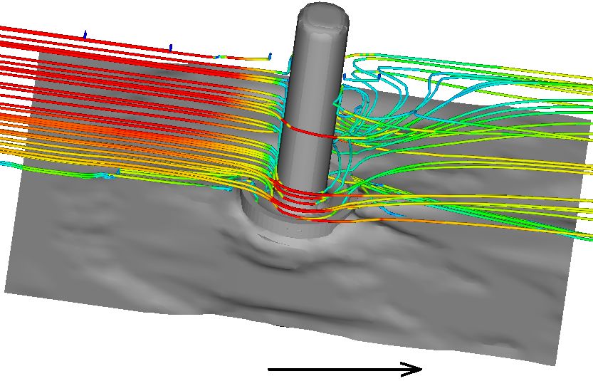
Water 2018, 10, 1251                                                                                               2 of 12

     Most previous studies have focused on designing the size, layer thickness and extent of the
riprap layer [7–9]. Critical velocity often dictates the size. In a combined setup of riprap and collar by
Mashahir et al. [10], scour volumes were reduced by up to 57%. Besides, Hamidifar et al. [6] applied
bed sills to reduce scour depth, and in their investigations, they reduced upstream and downstream
scour by 23% and 47%, respectively. Attaching a collar to the pier reduces the downflow and,
subsequently, the formation of the horseshoe vortex. The collar changes the flow pattern around
the pier by deflecting the downflow and decreasing the horseshoe vortex. Several research works
have reported the effectiveness of collars in reducing the local scour depth around piers [11–16].
Singh et al. [14] concluded that the efficacy of a collar in preventing scour is a function of its width
and its elevation relative to the bed surface. They found that a collar width of 2b wide placed at
−0.1b, where b is the pier width, resulted in a maximum reduction in scour depth for circular piers.
Zarrati et al. [15] showed that a collar three-times the pier diameter is effective at reducing scour depth
for rectangular piers. Previous studies have shown that collar performance is dependent on its size
and its location with respect to the stream bed. In evaluating trapezoidal collars, Khosravinia et al. [17]
demonstrated better collar performance with increasing width. Scour depth decreased by up to 37%.
However, installing a large collar may be a challenge in practical engineering. Earlier investigations
by [10,18] found collars with widths greater than 3b impractical.
     Considering the economics and ease of construction, reducing collar width is essential. This study
proposes a new type of collar, the hooked-collar, with reduced width when compared to previous
works [13,15]. Figure 1 shows schematic flow features around piers fitted with a collar and a
hooked-collar. The collar reduces the strength of the horseshoe vortex by deflecting the downflow
further from the pier. The hooked-collar attaches to a thin ring outside the collar, deflecting the
downflow in an upward direction, resulting in a weak downflow by which the pier may benefit.
The study further provides guidance to the choice of collar location with respect to the pier and
channel bed following earlier investigations by [18].
     Finally, to better understand the hydraulics and the effects of using the proposed hooked-collar,
numerical models are essential in addition to physical tests or experiments. Henceforth, the study
further validated laboratory experiments using a 3D numerical model, FLOW-3D.

                               (a)                                                    (b)

      Figure 1. Flow features around piers: (a) pier fitted with a collar; and (b) pier fitted with a hooked-collar.

2. Experimental Setup and Procedure
    Experiments were carried out in an 8 m-long, 0.3 m-wide and 0.6 m-deep glass-sided re-circulating
flume (Figure 2). A head tank located at the upstream of the main channel acted as a reservoir for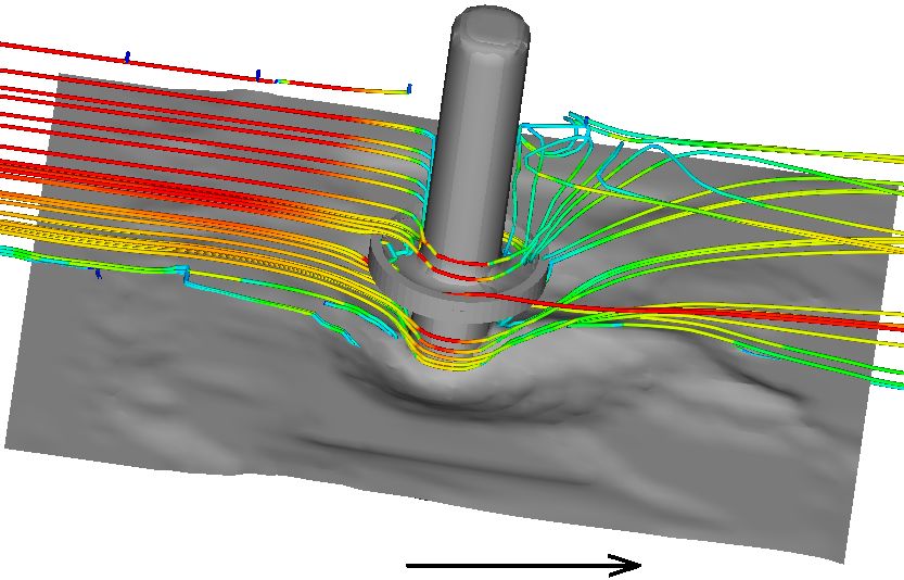
Water 2018, 10, 1251                                                                                     3 of 12

controlling flow discharge into the main channel. An electromagnetic valve controlled the flow
discharge in the flume such that it was fixed at 0.011 m3 s−1 . At the entrance of the main channel,
a trumpet-shaped inlet and a honeycomb smoothly guided the inflow to guarantee uniform flow
distribution, and at the outlet, a tailwater gate regulated and maintained flow depth.

                                                      (a)

                                                      (b)

      Figure 2. The flume system used for the experiments: (a) side view and (b) schematic diagram
      of the bridge pier and coordinate system. 1. Head tank. 2. Flow straightener. 3. Control panel.
      4. Acoustic Doppler Velocimeter (ADV). 5. Pier. 6. Sediment bed. 7. Main channel. 8. Tailwater gate.
      9. Re-circulating tank. 10. Pump. 11. Re-circulating pipe.

      Figure 2 shows a definition sketch of the working section. A circular cylinder of diameter b = 4 cm
was embedded at 5 m downstream of the flow straightener (see Figure 2a). Bridge piers were simulated
from Polyvinyl Chloride (PVC), while hooked collars of a 3 mm thickness were made from Perspex.
Observations made by Alabi [11] that collars whose thicknesses were less than 5 mm had no adverse
impacts on scour depth development guided the selection of the hooked collar thickness. The flume
channel was covered by a 10-cm thin layer of well-sorted sand having a median grain size of 0.69 mm
with geometric standard deviation σg = (d84 /d16 )0.5 < 1.20. Bridge pier diameter (b) was selected
to negate the effect of lateral walls on the scour pattern around the circular cylinder [19], yielding a
ratio of H = 5b, where H is the flow depth, a ratio not deviating much in practice. Additionally,
following the work of [2], we eliminated the effects of grain size on scour depth by the following
condition: b/d50 > 25. A hooked collar with a width (w) of 1.25b and a height (h) of 0.25b was used in
the experiments. Experiments were run under a clear water scour regime for 0.011 m3 s−1 of discharge
with a 0.20-m flow depth; depth was selected such that it was greater than 3.5 times the diameter of the
pier, thus eliminating its effect on the scour rate [19]. To avoid undesirable scour of the bed before the
tests, the flume was initially filled with water until the required flow depth was reached. Discharge
was gradually increased to the required depth. To enforce the clear water condition, the average
approaching flow was set to 0.9 of the critical velocity, which was calculated from the Shields’ diagram.
Scour depths were measured by a point gauge, to an accuracy of ±0.5 mm. An equilibrium state of
scour was attained when the scour depth did not change by more than 1 mm over a period of 6 h.
Two series of experiments were conducted: one with the collar and the other without. Hooked-collars
were placed at two bed levels, 0.25b above the bed and at the bed level. Earlier experiments by [18]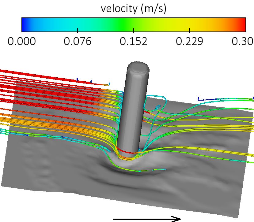
Water 2018, 10, 1251 4 of 12
guided the placement of the hooked-collars at the bridge piers. Experimental runs lasted more than
60 h when an equilibrium state of scour was reached. At this state, velocity samples were taken and
scour profiles recorded. A down-looking Acoustic Doppler Velocimeter (ADV), developed by SonTek,
was used for velocity measurements. Measurements were conducted along the vertical symmetrical
plane. At each measurement line, velocities were taken over the entire flow depth at heights separated
by 0.5∼1.0 cm. Flow velocity data at each position were recorded with a frequency of 25 Hz for 5 min.
These data were used to compute statistical properties, including time averaged velocities, Reynolds
stresses and turbulent kinetic energy (k).
3. Numerical Simulations
3.1. Model Setup
The increase in computational power has soared the application of numerical methods to
investigate scour in hydraulic structures. Burkow and Griebel [20] applied NaSt3D (Institute for
Numerical Simulation, Bonn, Germany) to simulate sediment transport and scouring at a rectangular
obstacle. A Computational Fluid Dynamics (CFD) model was modified by Xiong et al. [21] based on
Eulerian two-phase flow theory for bridge scour simulations. Török et al. [22] applied the 3D Reynolds
averaged Navier Stokes Equation (RANS) with the κ-ε model to account for turbulence. In modeling
local scour, Cheng et al. [23] developed an approximate methodology to account for the influence
of coherent structures on pier scour RANS simulations. Besides the RANS model, more advanced
models, demanding even much higher computational resources, have been used. Kirkil et al. [24]
applied a Detached Eddy Simulation (DES) to study turbulence at a circular pier having a scour hole.
In this study, we use FLOW-3D, a state of the art commercial software developed by Flow Science
(Santa Fe, NM, USA), to solve the RANS equations with the Renormalized Group (RNG) turbulent
closure, on a structured mesh. Since the grain size used in this study was between 200 and 2000 µm
[22], bed load sediment transport was computed by the van Rijn equation. The critical Shields number
was computed from the Shields curve using the Soulsby-Whitehouse equation [25].
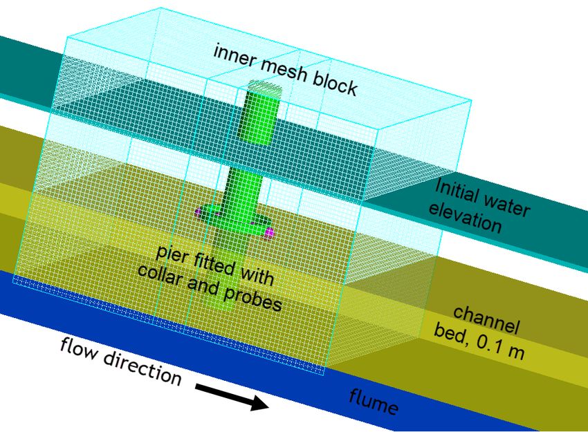
FLOW-3D contains a very simple, faster, yet powerful meshing capability through the Fractional
Area/Volume Obstacle Representation (FAVOR). This method offers an accurate way of representing
complex features (Figure 3) in the computational domain without the need of a fitted grid. It applies a
collection of distinct algorithms to enhance numerical stability, compute interfacial areas, advection and
stress along solid boundaries [25]. The computational mesh applied in this study contained 1.3 million
cells in 3 mesh blocks (outer, intermediate and inner) having uniform edge lengths of 0.01, 0.008 and
0.005 m, respectively. The outer block was located at cells farther from the pier, while the dense inner
block had piers and hooked collars installed (inner block shown in Figure 3). A compromise had to
be made between a very fine mesh and computational costs. A finer mesh could accurately capture
the hooked collar; moreover, the simulation time would have significantly increased; hence, we opted
not to use it. Additionally, Bayon et al. [26] when evaluating the performance of FLOW-3D and
Open-FOAM observed that FLOW-3D appeared less dependent on mesh size so long as the geometry
was well favorized. Maximum aspect and adjacent cell ratios determined the cell size distribution
within the blocks. These were respectively 1.02 and 1.03, which were well within the recommended
limits of 3 and 1.2 [25].
Dimensions of the computational domain, pier and parameters of the simulations corresponded
to the experimental setup as outlined in Section 2. At the inlet boundary, flow was fixed at a constant
discharge of 0.011 m3 s−1 following the laboratory setup, while at the outlet, a pressure boundary
condition was fixed with a fluid elevation of 0.2 m. To ensure correct discharge at the inlet boundary,
the computational domain was extended by −0.5 m in the upstream direction. No slip boundary
conditions were specified at the bottom and in lateral walls corresponding to sidewalls, which assigned
zero tangential velocity at the solid surfaces. The free surface, z max, was treated as stagnation pressure
and zero fraction fluid. The maximum turbulent mixing length and time step were dynamically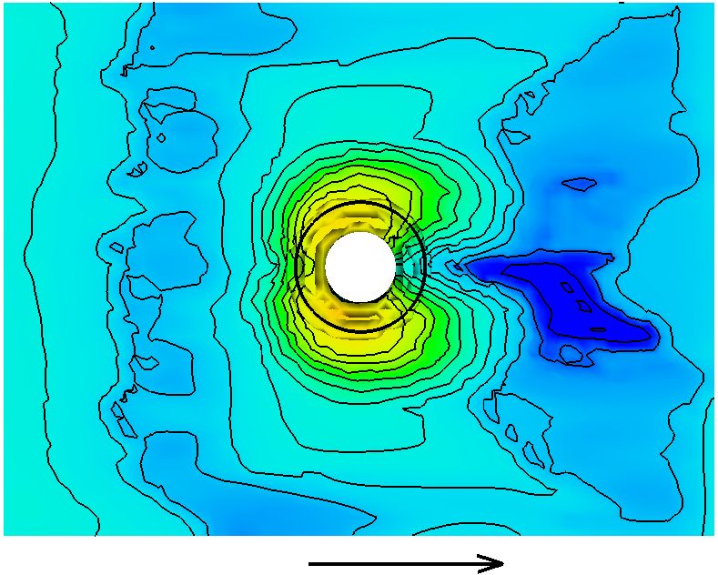
Water 2018, 10, 1251                                                                                        5 of 12

computed by the FLOW-3D code. To initialize the FLOW-3D model, a constant water depth of 0.3 m
was set in the computational domain, which allowed stability and faster convergence times.

                                     (a)                                         (b)

      Figure 3. An example of (a) a bridge pier and the hooked-collar installation, as well as the inner mesh
      block and (b) favorized image showing the hooked-collar geometry.

3.2. Model Validation
     The laboratory experiment in Section 2 was used to validate the model. Figure 4 shows the
comparison of maximum time-dependent scour depth observed in the laboratory and that of simulation.
Numerical results agree well with experimental data, despite FLOW-3D slightly overestimating the
scour depth beyond the 25 s of simulation for the no collar and the hooked-collar placed at 0.25b above
the bed. Moreover, it underestimated the maximum time-dependent scour depth of the hooked-collar
placed at the bed level (Figure 4).

                       Figure 4. Scour development for the different hooked-collar configurations.

4. Experimental Results

4.1. Hooked-Collar on Scour
     Figure 4 depicts observed scour patterns around a pier without a hooked-collar and piers fitted
with hooked-collars at different locations. The scour process of the single pier was consistent with
those reported by several studies [14,27–29]. Initially, the downflow dug a hole directly in front of
the pier (Supplementary Information, Figure S1). A horseshoe vortex removed the sediment from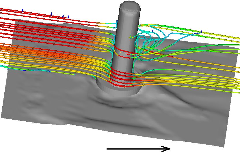
Water 2018, 10, 1251                                                                                       6 of 12

around the base of the pier, resulting in the development of a scour hole. As the scour depth increased,
the strength of the horseshoe vortex reduced, leading to a lower sediment transport rate from the base
region. An equilibrium state was eventually established when the transport rate from the base region
is equal to the transport rate into the region. In addition to scour around the pier, sediment deposition
occurred immediately downstream of the pier. The scour processes of the pier with a hooked-collar
differed from that without a hooked-collar. For the pier with a hooked-collar placed at 0.25b above the
bed, two grooves first developed downstream of the pier and moved upstream along the rim of the
pier (Supplementary Information, Figure S2). The scour hole later formed along the upstream face of
the pier. As these depressions joined each other at the downstream edge of the pier, the scour process
returned to the action of the horseshoe vortex, similar to the case of a single pier. For the piers with a
hooked-collar placed at the bed level (Supplementary Information, Figure S3), the scour hole was first
observed in a region ±90 of the pier. Two grooves gradually developed at the downstream rim of the
collar and extended downstream. No scour was observed at the immediate upstream of the pier.
     The pier without a hooked-collar resulted in maximum scour depth (Figure 5). The hooked-collar
positioned 0.25b above the bed reduced the scour hole by 24%, compared with the pier without a
hooked-collar. Installing the hooked-collar at the bed greatly improved collar performance, and no
scour was observed at the front and sides of the pier. The deepest scour hole was at the collar edge,
with a depth similar to the maximum scour depth in the experiment of a hooked-collar placed at 0.25b
above the bed. This finding is similar to observations by Kumar et al. [13]. Their study used a collar of
diameter 4.0b, which is much larger than that of the hooked-collar and which may not be practical
in practice. To reduce construction cost, using a hooked-collar may achieve similar performance to a
collar with a large width.

                       (a)                              (b)                                (c)

      Figure 5. Observed scour pattern around the piers: (a) bridge pier without the hooked-collar; (b) pier
      with the hooked-collar positioned 0.25b above bed; and (c) pier with the hooked-collar positioned at
      bed level.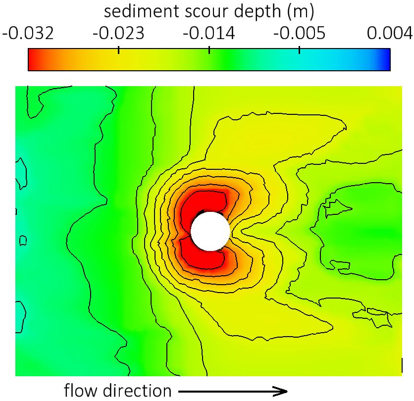
Water 2018, 10, 1251                                                                                         7 of 12

4.2. Numerical Results
      FLOW-3D was employed to simulate local scour around five configurations of a hooked-collar,
including three validation cases; no collar, single hooked-collar at 0.25b and a single hooked-collar at
the bed level (Figure 4). In all the configurations, an attempt was made to ensure similar properties
as the counterparts used in laboratory investigations. In addition, parameters used for validation in
FLOW-3D were used to simulate other collar configurations. In each computation, the simulation
lasted two days in an i7 7700k, 4.2 GHz, 4 cores, 8 logical processors and 64 GB of installed memory.
It is well documented that the horseshoe vortex is one of the key processes by which scour around
piers develops [11,23,30]. The Q criterion method, which defines a vortex as a connected fluid region of
the positive invariant of velocity gradient tensor (∇u) [31], was used. In the formulation, the vorticity
magnitude (Ω) prevailed over the magnitude of the strain rate (S). This method signifies that the
pressure in the vortex region was lower than the neighboring pressure.

                                                 1
                                           Q=      (kΩk2 − kSk2 ) > 0                                            (1)
                                                 2
     Identified vortices are shown in Figure 6. Mounting the hooked-collar at 0.25b showed a similar
vortex system to the no collar condition. Vortices were seen inside the scour holes in front of the cylinder
(Figure 6a,b). The hooked-collar in Figure 6b weakened the vortex; moreover, the coherent structure
was reactivated below the collar, a condition attributed to the scour pattern similarity. Conversely,
these structures were blocked by the presence of hooked-collars at the bed level, thus minimizing the
scour hole depth (Figure 6c,d).

                             (a)                                                  (b)

                              (c)                                                 (d)

      Figure 6. Visualization of vortices: (a) no hooked-collar; (b) single hooked-collar at 0.25b; (c) single
      hooked-collar at bed level; and (d) double collar at the bed and buried 0.25b.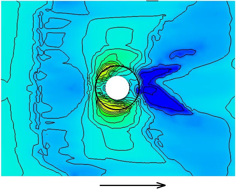
Water 2018, 10, 1251                                                                                            8 of 12

     Computed streamlines are shown in Figure 7. Downflow in front of the cylinders is visible and its
interception also shown where collars are placed at the bed surface. In front of the pier with no collar
and a pier fitted with a hooked-collar placed 0.25b above the bed, a single near-bed velocity stagnation
was observed, and this was caused by the horseshoe vertex illustrated in Figure 6 and incoming
flow. On the contrary, velocity stagnation in piers fitted with collars occurred within the collar, thus
preventing any scour in front of the pier. Interception of the intense downflow in front of the pier was
clearly demonstrated by the streamlines.

                              (a)                                                    (b)

                              (c)                                                    (d)

      Figure 7. Visualization of streamlines: (a) no hooked-collar; (b) single hooked-collar at 0.25b; (c) single
      hooked-collar at bed level; and (d) double collar at the bed and buried −0.25b.

    Figure 8 shows bed elevation contours. By observing the scour patterns, the scour shape
around the bridge-pier with or without a hooked-collar were similar (Figure 5). Scour patterns
were similar under no hooked-collar and collar attached at 0.25b above the bed level (Figure 8a,b).
Likewise, similar patterns were observed when the collar was placed at the bed level (Figure 8c,d).
Maximum scour was on the sides in the latter configuration, while in the former, scour was almost
around the pier. In all cases, the scouring patterns were almost symmetrical along the center of the
channel in the x direction with the exception of deposition downstream of the pier. The model in all
simulated cases underestimated deposition. In addition, deposition occurred farther from the pier
without a hooked-collar, differing from observed patterns, as is shown in Figure 5.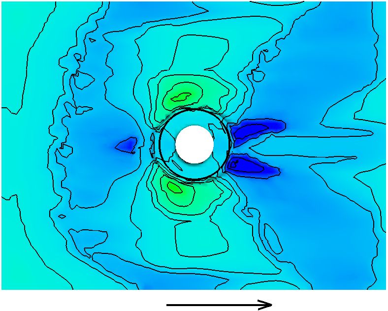
Water 2018, 10, 1251                                                                                       9 of 12

                             (a)                                                 (b)

                             (c)                                                 (d)

      Figure 8. Contours of scour depth: (a) no hooked-collar; (b) single hooked-collar at 0.25b; (c) single
      hooked-collar at bed level; and (d) double collar at the bed and buried −0.25b.

      Figure 4 shows scour development (dimensionless scour, ds /b) at the maximum scour region in
the simulated tests. The results of FLOW-3D at every 10 s was used to produce this figure. As illustrated
in Figure 8, the maximum scour occurred in mainly two regions; at the front of pier in the case of the no
collar pier, while it was on the sides when a hooked-collar was attached. At the early stage, the scour
rate was largest when there was no collar attached followed by a single collar attached at 0.25b. In both
cases, the rate increased quickly and reduced before reaching an equilibrium ds /b of 0.83 and 0.63 at
about 100-s and 160-s simulation time, respectively for the no collar and a single hooked-collar at
0.25b. Contrary to these configurations, when a hooked-collar was attached at the bed level or in a
double collar condition, the scour rate was gradually increased, followed by a brief sharp increase,
after which an equilibrium state was attained. Overall, the final scour depth was lowest when double
collars were applied (a decrease of 50% from the pier without collar), one at the bed level and another
installed at −0.25b from the bed. Moreover, in practice, a single collar may be enough considering the
insignificant difference between a single and a double collar-fitted pier. Additionally, in real rivers,
the live-bed scour condition exists where sediment load approaching the pier may be added in to the
scour hole [32]. This suggests that the sharp increase in scour development seen in Figure 4 may be
even less significant in a field setup.
Water 2018, 10, 1251 10 of 12
5. Conclusions
In this study, a hooked-collar that aims to reduce traditional collars is presented.
Laboratory experiments and numerical methods were applied to evaluate the performance of the
hooked-collar. To find its optimum placement at the bridge pier, 0.25b vertical adjustment was
implemented. A hooked-collar placed at 0.25b under the channel bed reduced the maximum scour
depth by 24%. With a single hooked-collar placed at the bed level, the final scour depth was reduced
42%, while a double collar, at the bed and 0.25b above the channel bed had the largest scour rate
reduction of 50%. During the initial scouring stages, the scouring rate increase was rapid with this
configuration, a similar pattern observed under the cylinder without any collar attached. Bed scouring
simulated by FLOW-3D was slightly above measured scour depths; moreover, the model captured
well the maximum time-dependent scour depth, as this was similar to observed flume experiments.
6. Patents
A United States Patent Number US7823240B2, entitled Hooked-Collar for Piers and Bridge
Including the Same, resulted from this work.
Supplementary Materials: The following are available online at http://www.mdpi.com/2073-4441/10/9/1251/s1.
Author Contributions: Hooked collar design and patent, S.-C.C. Numerical simulation and writing,
S.T. Laboratory experiments, T.-Y.W. Data verification H.-C.C. and H.-T.C.
Funding: This research was funded by the Ministry of Education under the Higher Education Sprout Project.
Acknowledgments: The authors are thankful to the anonymous reviewers of this work, and special thanks are
given to Den-Yi Wang and Shiao-Chia Yen.
Conflicts of Interest: The authors declare no conflict of interest.
Abbreviations
The following abbreviations are used in this manuscript:
b pier diameter
w hooked collar width
h hooked collar height
ds scour depth
d50 medium grain diameter
d84 grain size for which 84% of the bed is finer
d16 grain size for which 16% of the bed is finer
H flow depth
k turbulent kinetic energy
0
u time averaged streamwise velocity u
0
ν time averaged transverse velocity ν
0
w time averaged vertical velocity w
σg geometric standard deviation
g gravity acceleration (m s−2 )
Ω vorticity magnitude
S strain-rate magnitude
References
1. Lee, C.H.; Xu, C.; Huang, Z. A three-phase flow simulation of local scour caused by a submerged wall jet
with a water-air interface. Adv. Water Resour. 2017. [CrossRef]
2. Melville, B.W.; Coleman, S.E. Bridge Scour; Water Resources Publications, LLC: Highlands Ranch, CO,
USA, 2000.
3. Das, S.; Das, R.; Mazumdar, A. Circulation characteristics of horseshoe vortex in scour region around circular
piers. Water Sci. Eng. 2013, 6, 59–77. [CrossRef]Water 2018, 10, 1251 11 of 12
4. Mete, K.; George, C. An investigation of the flow and scour mechanisms around isolated spur dikes in a
shallow open channel: 1. Conditions corresponding to the initiation of the erosion and deposition process.
Water Resour. Res. 2008, 44. [CrossRef]
5. Froehlich, D.C. Protecting bridge piers with loose rock riprap. J. Appl. Water Eng. Res. 2013, 1, 39–57.
[CrossRef]
6. Hamidifar, H.; Omid, M.H.; Nasrabadi, M. Reduction of scour using a combination of riprap and bed sill.
Proc. Inst. Civ. Eng.-Water Manag. 2017, 1–7. [CrossRef]
7. Lauchlan, C.S.; Melville, B.W. Riprap protection at bridge piers. J. Hydraul. Eng. 2001, 127, 412–418.
[CrossRef]
8. Chiew, Y.M.; Lim, F.H. Failure behavior of riprap layer at bridge piers under live-bed conditions.
J. Hydraul. Eng. 2000, 126, 43–55. [CrossRef]
9. Yoon, T.H.; Yoon, S.B.; Yoon, K.S. Design of Riprap for Scour Protection around Bridge Piers. In Proceedings
of the 26th IAHR Congress, London, UK, 11–15 September 1995.
10. Mashahir, M.B.; Zarrati, A.R.; Mokallaf, E. Application of riprap and collar to prevent scouring around
rectangular bridge piers. J. Hydraul. Eng. 2010, 136, 183–187. [CrossRef]
11. Alabi, P.D. Time Development of Local Scour at a Bridge Pier Fitted with a Collar. Ph.D. Thesis, University of
Saskatchewan, Saskatoon, SK, Canada, 2006.
12. Chiew, Y. Scour protection at bridge piers. J. Hydraul. Eng. 1992, 118, 1260–1269. [CrossRef]
13. Kumar, V.; Raju, K.G.R.; Vittal, N. Reduction of local scour around bridge piers using slots and collars.
J. Hydraul. Eng. 1999, 125, 1302–1305. [CrossRef]
14. Singh, C.P.; Setia, B.; Verma, D.V.S. Collar-sleeve combination as a scour protection device around a circular
pier. In Proceedings of the 29th IAHR Congress, Beijing, China, 16–21 September 2001.
15. Zarrati, A.R.; Gholami, H.; Mashahir, M.B. Application of collar to control scouring around rectangular
bridge piers. J. Hydraul. Res. 2004, 42, 97–103. [CrossRef]
16. Zarrati, A.R.; Nazariha, M.; Mashahir, M.B. Reduction of local scour in the vicinity of bridge pier groups
using collars and riprap. J. Hydraul. Eng. 2006, 132, 154–162. [CrossRef]
17. Khosravinia, P.; Malekpour, A.; Hosseinzadehdalir, A.; Farsadizadeh, D. Effect of trapezoidal collars as a
scour countermeasure around wing-wall abutments. Water Sci. Eng. 2018, 11, 53–60. [CrossRef]
18. Chen, S.C.; Wang, D.; Chou, H.; Yen, S. The Efficacy of hooked-collar on reducing bridge pier scour. J. Taiwan
Water Conserv. 2007, 55, 26–37.
19. Chiew, Y.M.; Melville, B.W. Local scour around bridge piers. J. Hydraul. Res. 1987, 25, 15–26. [CrossRef]
20. Burkow, M.; Griebel, M. A full three dimensional numerical simulation of the sediment transport and the
scouring at a rectangular obstacle. Comput. Fluids 2016, 125, 1–10. [CrossRef]
21. Xiong, W.; Tang, P.; Kong, B.; Cai, C. Reliable bridge scour simulation using Eulerian two-phase flow theory.
J. Comput. Civ. Eng. 2016, 30, 04016009. [CrossRef]
22. Török, G.; Baranya, S.; Rüther, N. 3D CFD modeling of local scouring, bed armoring and sediment deposition.
Water 2017, 9, 56. [CrossRef]
23. Cheng, Z.; Koken, M.; Constantinescu, G. Approximate methodology to account for effects of coherent
structures on sediment entrainment in RANS simulations with a movable bed and applications to pier scour.
Adv. Water Resour. 2017. [CrossRef]
24. Kirkil, G.; Constantinescu, G.; Ettema, R. Detached eddy simulation investigation of turbulence at a circular
pier with scour hole. J. Hydraul. Eng. 2009, 135, 888–901. [CrossRef]
25. Flow Science. Flow-3D User Manual: v10.1; Flow Science, Inc.: Santa Fe, NM, USA, 2012.
26. Bayon, A.; Valero, D.; García-Bartual, R.; Vallés-Morán, F.J.; López-Jiménez, P.A. Performance assessment
of OpenFOAM and FLOW-3D in the numerical modeling of a low Reynolds number hydraulic jump.
Environ. Model. Softw. 2016, 80, 322–335. [CrossRef]
27. Muzzammil, M.; Alama, J.; Danish, M. Scour prediction at bridge piers in cohesive bed using gene expression
programming. Aquat. Procedia 2015, 4, 789–796. [CrossRef]
28. Nouri Imamzadehei, A.; Heidarpour, M.; Nouri Imamzadehei, M.; Ghorbani, B.; Haghiabi, A. Control of the
local scouring around the cylindrical bridge pier using armed soil by geotextile. Int. J. Geosynth. Ground Eng.
2016, 2, 5. [CrossRef]
29. Zarrati, A.R.; Chamani, M.R.; Shafaie, A.; Latifi, M. Scour countermeasures for cylindrical piers using riprap
and combination of collar and riprap. Int. J. Sediment Res. 2010, 25, 313–322. [CrossRef]Water 2018, 10, 1251 12 of 12
30. Baykal, C.; Sumer, B.M.; Fuhrman, D.R.; Jacobsen, N.G.; Fredsøe, J. Numerical simulation of scour and
backfilling processes around a circular pile in waves. Coast. Eng. 2017, 122, 87–107. [CrossRef]
31. Kolář, V. Vortex identification: New requirements and limitations. Int. J. Heat Fluid Flow 2007, 28, 638–652.
[CrossRef]
32. Dey, S. Time-variation of scour in the vicinity of circular piers. Proc. Inst. Civ. Eng. Water Marit. Energy 1999,
136, 67–75. [CrossRef]
© 2018 by the authors. Licensee MDPI, Basel, Switzerland. This article is an open access
article distributed under the terms and conditions of the Creative Commons Attribution
(CC BY) license (http://creativecommons.org/licenses/by/4.0/).You can also read