A JEE-based Architecture for Distributed Multi-Domain Resource Accounting
←
→
Page content transcription
If your browser does not render page correctly, please read the page content below
2010 Sixth IEEE International Conference on e–Science Workshops

                 A JEE-based Architecture for Distributed
                   Multi-Domain Resource Accounting
                                          Michael Brenner, Jan Wiebelitz and Matthew Smith
                                                  Gottfried Wilhelm Leibniz Universität
                                                   Distributed Systems Security Group
                                                Research Center L3S, Hannover, Germany
                                             {brenner,wiebelitz,smith}@dcsec.uni-hannover.de

    Abstract—Many different accounting systems currently exist            it is even more desirable to eventually speak a common lan-
 for the European Grids and for other distributed systems in              guage, which makes the exchange of accounting information
 general. Even though they often share equivalent technical               feasible. It also allows building a multi-domain accounting
 approaches, concerning accounting metrics and batch-system
 log access, there are lots of different data formats, accounting-        network in which each domain controls its own information
 database layouts, communication- and implementation details              and propagates data to a higher administrative level, in a form
 that hinder a consistent and comprehensive accounting of dis-            that considers both, technical and legal issues.
 tributed resources. An eventual technical convergency is even               Most existing accounting systems are sort of an evolutionary
 more required, as the National Grid Initiatives move forward             product that started with the requirement to only consider local
 to constitute a European Grid that comprises the national
 infrastructures. We present EEGAS, a Java Enterprise based               clusters and batch systems. As a consequence, representative
 grid accounting system, that addresses the current problems. Our         systems like the Distributed Grid Accounting System (DGAS)
 system makes use of standard building blocks, where possible,            do provide a hierarchical infrastructure option [1] but use
 to achieve high scalability and application server console-based         proprietary data exchange formats and proprietary relational
 configurability. It serves as an integration point for existing          database layouts [2] [3]. The Accounting Processor for Event
 accounting systems and uses the OGF-UR data format, which we
 use to generate a Java domain model and a database schema. We            Logs (APEL) makes use of a messaging system with unified
 also present sensor components for CPU and storage accounting,           data formats, but is a single domain system, which only allows
 resource capacity discovery, as well as different message- and           one central authority [4].
 service-based transport components that support a fault-tolerant            To face the challenges of the converging European Grids we
 operation of a distributed accounting network that features              propose our accounting system EEGAS, that bases on the well
 different administrative domains rather than a single centralized
 accounting authority.                                                    defined Java Enterprise Architecture and the OGF-UR record
    Index Terms—EEGAS, Distributed Resource Accounting, Ca-               format. We have designed a distributed accounting architecture
 pacity Discovery, Java EE, OGF-UR                                        that satisfies the identified requirements. Originally intended as
                                                                          an infrastructure extension to DGAS, EEGAS has evolved to-
                        I. I NTRODUCTION                                  wards a comprising accounting solution with enhancements to-
                                                                          wards distributed resource discovery and support-functionality
    The current landscape of distributed resource accounting              for meta-scheduling.
 is fairly spacious. When examining the different existing                   The paper structure is as follows: in Section II we discuss
 accounting systems, we find many similarities concerning the             the Java Enterprise Architecture and the platform components
 technical approaches. Often the data about resource usage is             that we will use to construct our application architecture. We
 gained by accessing the log files of the underlying resource-            briefly describe the function of each required part of the Java
 systems. This information is then interpreted and correlated             ecosystem and how it fits in the big picture. Section III defines
 to meet the requirements of the different accounting metrics             our accounting system’s elements and how they map on the
 for CPU, storage or license usage. In contrast to the common             Java architecture components. We discuss the data format, the
 conceptual aspects, we face large differences in the imple-              transport mechanism, sensor technology and other functions,
 mentations. The most important problem is, that there is no              as a foundation for the following sections. The distribution
 unified data format; a fact that makes interoperability between          model of our accounting system is presented in Section IV.
 different systems extremely tedious and even avoids it in most           We will show, how different requirements to the data-flow
 cases. As a direct consequence, we lack a common data format             and physical component distribution can be satisfied using
 to exchange accounting data. The Usage Record Format that                our system’s elements. We describe sample configurations for
 has been defined by the Usage Record Working Group of the                common accounting scenarios with different domain models
 Open Grid Forum has still not been widely accepted since the             and sketch how distributed resource capacities can be tracked
 latest version.                                                          within these domains or by a central authority.
    Being at the beginning of the transition phase from the                  Section V gives a resource discovery scenario and briefly
 European EGEE project to the European Grid Initiative EGI,               describes the required steps to integrate the functionality into

978-0-7695-4295-9/10 $26.00 © 2010 IEEE                              31
DOI 10.1109/eScienceW.2010.15
a meta-scheduler. The web delivery function (tier 1) is a combination of a
Implementation details are discussed in Section VI. We pro- web server and a container for special java objects (servlets),
vide information on special issues when using the accounting that handle web traffic and generate web pages for client-side
components and the underlying frameworks. display. This sort of connection also applies to web-service
Related work and The conclusion is provided in Section connections that use servlet driven machine-generated inputs
VII. and machine-readable outputs. A servlet is a simple java object
that has to implement a set of methods that allow the servlet
II. T HE JAVA E NTERPRISE A RCHITECTURE container or web container to pass http requests and to receive
The Java Enterprise Edition (JEE) is a specification of http responses from it for delivery to the client. The JBoss
an architecture and software platform that handles complex, application server is shipped with the Apache Tomcat web
transactional, component-based Java systems. This usually, but container, which comprises the Apache Coyote web server and
not necessarily comprises a web-based front-end and often the Apache Catalina servlet engine.
a database backend. There are several free and commercial JEE specifies a couple of methods to allow mid-tier com-
implementations of the JEE specification and almost any ponents to interact with backend-systems. One framework is
existing framework or component in the Java ecosystem can the Java Messaging Service (JMS) that defines interfaces to
be connected to a JEE application, which reduces individual a message-oriented middleware. This is a system that handles
programming effort. This section gives a brief introduction to typical messaging patterns and modes. It is responsible for the
JEE and the typical components and frameworks as depicted reliable delivery of messages from a message producer to a
in Figure 1. message consumer. The consumer and one or more producers
communicate by exchanging messages over a message queue
Application
that can sort and deliver messages according to different
Server properties like priority or order, which can be configured.
For our implementation, we apply the Apache ActiveMQ as
Web-Container Bean-Container
a messaging provider that implements the JMS specification.
Web-Service
Client
Axis EJB JEE defines a way to store application data and to save the
state of an application by persisting the objects that represent
the application. This requires an application to use enterprise
Message
JMS JPA JCA Data
beans that implement methods for a transparent database
Client
access. The Enterprise Java Beans (EJB)-specification claims
the functionality of object-relational mapping, which is re-
quired to manage a relational database using the corresponding
Fig. 1. Basic JEE-based Architecture java domain model. The system, that we describe here, uses
JBoss Hibernate, which is a reference-implementation of the
The application server is the main entity of any JEE installa- EJB3-specification and the Java Persistence API (JPA), that
tion. It serves as a central piece of a puzzle, to which different uses advanced Java-technologies like runtime class-reflection,
loose pieces are connected and form the infrastructure that’s dynamic SQL generation and annotations.
required for a particular application or set of applications. It For access to other systems, JEE defines a set of inter-
essentially is a runtime environment or container for Java faces in the Java Connector Architecture (JCA). Connectors
components, that obey the JEE specification (often called typically provide access to databases or other resources like
enterprise beans), and a number of interfaces that connect mainframes or transaction monitors, but also to messaging, like
the JEE components to each other, to external components mentioned before. The core function is to handle connections
or systems and that provide typical services to components. and transactions that are used to communicate with a remote
The application server handles the life-cycles of the objects entity. For this purpose the resource adapter implements three
that belong to a component and it is also responsible for system contracts that specify the behavior of connections (1),
the management of transactions and object persistence. A transactions (2) and security (3) of the connected resource. In
distributed web application is often divided into three tiers, our accounting system, we use the JCA-spec to integrate a
which are basically software layers that combine groups of MySQL database system into the JEE-environment. For this
actions required for a certain state of an application. In this purpose we provide a specific MySQL connector-library that
sense, the enterprise bean container which is the core of the matches the connector architecture on the server’s end and
application server, is the perfect middle of this architecture applies to the Java Database Connection specification (JDBC)
(the mid-tier), because it handles the actual business logic of on the other side.
an application but also provides a server-side client tier (the The JCA is designed to decouple i.e. the database system
web delivery function) and a rear end that connects to possibly from other components running in the application container,
different backend systems (the data tier). The mentioned rear like the persistence mechanism, and to use an abstraction
end can also point to the front, when it is configured to handle that can be easily configured over the application server’s
certain client message types. administration console. The application server can also take
32care of a connection pool which optimizes the network access and multiplier, as well as a content-based routing element.
to a resource. To achieve this, the resource adapters register To operate the relayer, a proper configuration has to be
their connections and resources to the application server and its provided, that defines the inbound message queue and one or
naming service. The applications discover required resources more outgoing queues. A sample configuration for a basic,
by querying the JNDI (Java Naming and Directory Interface), unconditional forward operation is given in Listing 1.
that implements access to the naming service.
III. ACCOUNTING S YSTEM C OMPONENTS inBroker = t c p : / / s r c b r o k e r . com : 6 1 6 1 6 ;
queue / c l i e n t Q u e u e
This chapter defines our accounting system’s elements and o u t B r o k e r = t c p : / / d s t b r o k e r . com : 6 1 6 1 6 ;
how they map on the Java architecture components. We give queue / dgasInbound
a detailed description of the system’s parts, like the data Listing 1. Relay Configuration
format, the transport mechanism, sensor technology and other
functions, as a foundation for the following chapters. The configuration parameters for each end of the
communication channel contains the host address (broker
A. Transport Framework url) and the queue name on that particular broker. On
The transport framework is one of the core features of relay startup, a connection to both ends of the channel is
our accounting system. By offering both, a web-service inter- established. ActiveMQ offers a failover feature that has
face and message-based communication, we support a multi- two advantages: we can force an automatic reconnect in
channel strategy to access the accounting data repository. The case an established channel gets disconnected, and we may
web-service interface is a way to support lightweight clients or provide a number of broker-URLs that build a failover group
clients that come as embedded components in existing service- of distributed brokers. The basic failover-configuration for
infrastructures. However, the focus of our transport-framework unconditional forwarding is shown in Listing 2.
is on the messaging system.
inBroker = failover :(
Webservice Frontend t c p : / / s r c b r o k e r . com : 6 1 6 1 6 ) ;
One channel to submit or to access accounting data is queue / c l i e n t Q u e u e
the web-service interface. Using this interface is very easy, outBroker = f a i l o v e r : (
t c p : / / d s t b r o k e r . com : 6 1 6 1 6 ,
since the appropriate stubs and data model components can be t c p : / / d s t b r o k e r 2 . com : 6 1 6 1 6 ) ;
automatically generated from the provided WSDL-definition. queue / dgasInbound
This channel can be used for embedded service-based compo-
nents as well as for the dedicated sensor components. So, the Listing 2. Failover Relay Configuration
decision, which channel should be used in a given scenario, To configure the relay as a message multiplier, we just add
is up to the system architect. outQueueNames and outBrokerUrls for every destination broker
or every group of failover brokers.
Message Bus Components
The central transport mechanism in our architecture is a Content-based Message Routing
message bus (in other terms a store-and-forward network An important function of the relay component is the ability
federation), which consists of a number of distributed to perform a content-based routing. This feature allows to
message queues in a broker network. It is implemented on decide, which next receiver is appropriate for a particular
top of the Apache ActiveMQ messaging middleware and message, according to the contents or message headers.
handles all internal traffic on the servers and relay nodes. Content-based routing is only available for the unencrypted
Additionally to the Axis-based web-service gateway, remote parts of a message that are readable by the relayer. For
clients and relays can also send messages to the bus directly, routing operation, we have to define a selection condition for
using a message protocol. This approach unifies the data flow each conditional destination. A selector is formulated as a
and allows easy support of a multi-channel strategy, which regular expression that is applied on the message content and
decouples the business logic from the data input channel. / or the message header. A routing condition with a message
Furthermore, we provide message relay components that can header selector and a message content selector is depicted in
be deployed on every site as network-concentrators and to Listing 3.
order message transport and to support failover features. The
outBroker =
message relay component is the most important element to t c p : / / d s t b r o k e r 1 . com : 6 1 6 1 6 ;
queue / dgasInbound ;
build a hierarchical or networked accounting infrastructure. header (
jmsConsumerIdentifier=broker1 | broker2 )
It requires a dedicated ActiveMQ installation, which is used outBroker =
t c p : / / d s t b r o k e r 2 . com : 6 1 6 1 6 ;
to collect, order and forward messages, according to the queue / dgasInbound ;
content (
local relay policy. The relayer also provides content-based gcwn[0−90−9]\. u n i−h a n n o v e r \. de )
message routing functions that are required to build a flexible
infrastructure. The relayer acts as both, as a message repeater Listing 3. Route Condition
33The presented mechanisms, which are contained within C. Accounting Authority
the relay- and routing-component, support the construction of
complex and flexible, distributed infrastructures. To complete Located in the technical center of an accounting domain is
the bus component overview, we describe the addressing the message core. Essentially this is a message queue with a
schema for the messages. connected message handler that receives accounting messages
for its own domain, but can also be used to obtain data that
Message Addressing Schema has to be preprocessed before being forwarded to a higher
To allow indirect addressing of components that can only level accounting authority. The result of preprocessing may
be reached over relay hops, we have to define an addressing be some sort of aggregate record that’s supposed to conceal
schema, that contains at least two receiver identities. The the composition of a distributed job or just to condense the
schema, that we use here refers to Web-Service Addressing information, while delivering the metric-dependent figures,
(WS-A). The first identity is that of the ultimate receiver. like summarized CPU-time or memory usage. The message
This is the accounting authority, which is responsible for a core is an integral part of the accounting authority component.
particular accounting record. The other identity is the next We have implemented the accounting core by means of the
receiver in the sense of a relay hop. Thus, the next receiver JEE message-driven enterprise-bean concept for the following
changes during the travel to the ultimate receiver on every reasons. First, the integration into a complex infrastructure is
visited relay, according to the relay’s routing policy. The simplified, because it’s possible to deploy a message-driven
receiver information is implemented using JMS properties, that bean into the bean-container. Second, the bean can use all the
are appended to the messages. However, all infrastructure com- abstractions of resources that the container provides. Third, to
ponents may or may not evaluate the addressing information face load issues, we are able to deploy a number of uniform
and are allowed to override that information to comply with message-beans that help scaling the application performance.
a local forwarding policy. An accounting domain is defined by its central account-
B. Sensors ing authority (AA). This is the responsible entity for the
accounting- and capacity-data of all connected sites. To deploy
Sensors are deployed on the distributed resources to record
an AA, the installation of the application server along with a
usage data. The sensors in our architecture feature a modular
message broker is required. The AA grants full data access to
design with a sensor core and two plug-ins, one on each side.
the domain administrator and administrative processes, thus
The resource-side plug-in gathers the required information
allowing data processing as required by local accounting-
on the resource, according to the various accounting metrics.
or economic policies. The AA installation also features the
The bus-side module handles the transport and can be
functions to preprocess data in order to meet the requirements
web-service- or message-driven. Each tuple of a reportable
of a higher-ranking authority and to provide information on
measure and a transport-model requires a appropriate plug-in
available capacities in real-time. The processing model, that’s
configuration for the sensor. A sample configuration for a
implemented by the authority component, consists of three
Torque CPU accounting via the message system is shown in
stages. Stage one is the preprocessing stage, where data
Listing 4.
manipulation and aggregation can be configured. The second
stage is the redirector, which decides, if a message has to be
a d a p t e r C l a s s = de . d g a s . e e . s e n s o r s . t o r q u e . Log re-routed after preprocessing and therefore is delivered back
p a r s e r C l a s s = de . d g a s . e e . s e n s o r s . t o r q u e . P a r s e r
c o n n e c t o r C l a s s = de . d g a s . e e . s e n s o r s . c o n n e c t o r . Mq to the message bus, where the routing and forwarding policies
are applied again. If the message proceeds to the third stage,
Listing 4. Sensor Configuration then it is stored by the local database persistence mechanism.
The adapter class defines the method to access the ac- The structure is shown in Figure 2.
counting information. In the sample case this is the Torque
log file which can be easily accessed with a file reader. The
Accounting Core
parser class is the module that implements the handling of
a specific content structure. In particular, the parser plug-in
has to produce a valid OGF record from the batch-system
specific accounting record. To achieve this, it makes use of the Stage 1 Stage 2 Stage 3
Java data-mapping framework, that we have implemented and preproc. redirect persist Database
that is described in section III-E. The connector class points
to the communication handler module. The sample shows
the selection of the message-based communication handler.
Message Bus
In order to report real-time resource allocation figures to the
authority, the sensor is operated in early record release mode
which reports the resources that are assigned a particular job in
a pending record, only containing the job start time. Resources Fig. 2. Accounting Core Architecture
with a pending job end time are considered occupied.
34D. Database and Hibernation
Sensor Relay Router AA RDBMS
EEGAS uses a relational database model which is a rep-
resentation of the OGF-UR draft definition. The automatic
generation is achieved using the XML-Beans framework which OGF XML OGF XML OGF XML DML
is also in charge of translating between the XML data streams
and the java object model. The physical access to the relational Java CM Java CM
database is encapsulated in the Hibernate-framework, which is
providing OR-mapping and implements the Java Persistence
API. The database connection is represented by a JDBC- Fig. 3. Data Formats and Flow
datasource and handled by the application server’s connection
pool.
If the AA has to process the record before persisting it, it
E. OGF Message Format transforms it from XML to the Java object model and back to
The Open Grid Forum has defined the record format to XML before passing it to the database handler or the message
support sharing of distributed resources, where sites must be handler. The situation on a router, that has to read and write
able to exchange basic accounting and usage data in a common addressing information of a record, is similar.
format. The OGF UR Format Recommendation focuses on the The direct mapping from XML to DML results in a series
representation of resource consumption data. The record for- of SQL commands that are generated from an SQL template
mat is intended to be specific enough to facilitate information and the extracted strings from the XML record. This method
sharing among grid sites, yet general enough that the usage avoids the instantiation of a fully featured Java object-tree
data can be used for a variety of purposes: traditional usage to represent the XML-record and yields a smaller runtime
accounting, charging, service usage monitoring, performance memory-footprint.
tuning, etc. The format recommendation outlines the basic We have run a series of tests with large numbers of mes-
building blocks of the accounting record, and how to properly sages, to figure out, what’s the impact of our data-transition-
represent it. Regarding the participating assets, the format model on the overall messaging performance. The results are
definition bases on a couple of assumptions. The fundamental displayed in section VI.
grid component is a resource and the fundamental consumer is
a grid job. These jobs may be interactive or batch-driven and IV. C OMPONENT D ISTRIBUTION M ODELS
the usage recording is either detailed or in an aggregated form. The described components give us the opportunity to model
The basic record consists of a number of base properties that different distribution scenarios. Especially the deployment of
represent most basic job accounting activities. Additionally message-based components allows a flexible infrastructure that
there are differentiated properties that can hold the figures helps minimizing the effects of network failures. A subtle
for metrics that occur more than once in one single record. layout of message relayers can also improve the performance
To be able to model grid- and site-specific additions to the of the entire network of accounting components, and it thus
accounting record, the UR-schema defines extensions. Sites helps to deal with load issues, as we will show in this
that exchange extended records must agree on a joint extension section. Furthermore the structure of our components enables
model [6]. the definition of different accounting domains that reflect the
EEGAS features a flat Java object model as a representation actual responsibility for the collected accounting data and the
of the OGF-UR schema and a relational database model for relationship between the participating resource providers and
persistence. These models have been automatically generated the administrative entities.
from the OGF-UR XML-schema. The transformation into The main transport mechanism for messages in the ac-
the Java model is carried out by the XMLBeans framework. counting system is the message bus. We implement it by
All processing on the accounting data is performed in the deploying a server instance of Apache ActiveMQ on every
resulting Java object model. The wire format is the OGF site that participates in routing and relaying. The resulting
XML-representation and this format is used in most cases distributed message handling is a appropriate vehicle that
from the sensor component to the backend database handler. can handle large message loads while complying with formal
So all components communicate via XML which makes it routing policies, that can be adjusted locally on every site,
easier to integrate third-party components into our data flow, according to technical and legal requirements. Legal issues
as long as they understand and produce the OGF format. The may arise when accounting data is indirectly submitted to the
format transitions in a typical accounting workflow are shown accounting authority, using third-party relays in the network.
in Figure 3. However, all message transfers in our accounting infrastructure
The translation between the XML format and the database are encrypted utilizing the cryptographic capabilities of the
data manipulation language (DML) is not object-driven. This underlying transport technology. In case of the web-service
means, that in cases where no preprocessing is required, the binding that’s the WS-Security specification, the message-
database handler takes the XML record directly from the channel uses the provided network connector security model,
accounting authority and maps it on the database schema. which is a configuration-item in ActiveMQ.
35The basic component distribution is the classic client-server this scenario, we still keep the client-to-relay communication
pattern, which deploys one central server, to which all the inside our own network-domain where we can control and
clients connect and submit their data. The resulting single maintain the connectivity. The site-centric relay acts as some
domain, depicted in Figure 4 doesn’t require relaying or sort of network concentrator, which routes the traffic over a
routing, from an architectural point of view. Nevertheless, we dedicated connection factory with one single point of admin-
can improve data safety and performance by applying the relay istration.
patterns that we discuss in next few paragraphs.
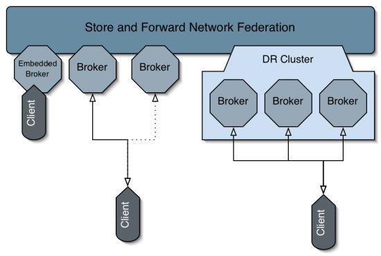
Store-and-forward Network Federation
By interconnecting the relay components in different do-
mains, we construct a single overlay bus structure. In com-
Sensor Sensor Sensor
bination with the message addressing schema, all connected
components are able to reach every participating component
directly or via one or a number of relays. We provide different
Web-service Messaging
possible topologies for the connection of relays to the message
Client Client bus, as sketched in Figure 5 and [9].
Resource Resource
DGAS-EE
Accounting Authority
Fig. 4. Single Domain Case
A. Client-side Message Relay
One serious problem in a client-server based communication
environment is the exception handling on the client side. A
simple client that only wants to transmit uniform data records, Fig. 5. Broker Topologies [9]
has to be aware of a couple of difficulties that occur in case of
a non-reachable server system. There are numerous strategies
for a client-side incident response, but after a few retries and C. Multi-Domain Deployment
persisting data on a local storage, a client-component has The deployment of the accounting system in a distributed
to report the failure to the higher application layers, to take multi-domain environment is the key feature of our concept.
further action. The use of the messaging system simplifies this By applying the described components, we can model arbitrary
situation, because we can completely delegate the message component topologies. Figure 6 shows a possible case of
handling to a self-contained subsystem with a decent failover- multi-domain distribution.
functionality and database-driven persistence. The fact, that
the message broker and the client can be deployed on the
same physical system minimizes the danger of network failures
between client and broker. As a consequence, the client doesn’t
have to store the records locally for later transmission and it
Resource Resource Resource Resource
doesn’t have to schedule the retries for the connection. The
client-side relay approach suffers from the drawback, that we
have to install a message broker, but on the other hand the Accounting Authority Accounting Authority
client’s exception handling can be kept simple. The client-
side relay model enables us to tap infrastructures, where only
a few sensors with high data-rates are operated, or where the
sensor resides in a network segment that provides only limited Accounting Authority
reliability.
B. Site-centric Message Relay Fig. 6. Multi Domain Case
In cases, where a number of accounting sensors are de-
ployed, the client-side relay approach might cause a con- The convergence of the European Grids requires a hierarchi-
siderable overall-footprint. To achieve a more lightweight cal model of accounting authorities. Every participating Euro-
component distribution, we propose the site-relay model. In pean country runs its own National Grid Initiative (NGI) with
36an appropriate facility to support accounting. The accounting Performance Test
of the European Grid Initiative (EGI) is the (vertically) higher-
We have run a series of tests with large numbers of
ranked authority that collects and correlates accounting data
messages, to figure out, what’s the impact of our data-format
from the underlying national initiatives. In addition to such
transition-model between the components (see Figure 3) on
a scenario, we are able to define a number of horizontally
the overall messaging performance. The component setup for
arranged domains that only operate on a limited range of
our test is displayed in Figure 7.
the accounting information. This would be useful to design a
component distribution with separation-of-concerns, where an
authority is responsible for selected excerpts of the accounting Test Host
data.
The multi-domain deployment is different from the site- Accounting
Sensor Relay
centric relay-model, because in the case of a simple relay, we Authority RDBMS
do not deploy an entire accounting authority. Every domain
in the multi-domain model has its own authority and a true
responsibility for accounting data in the overall accounting- Message Bus
workflow.
V. R ESOURCE D ISCOVERY
In order to discover a resource for a particular job, the Fig. 7. Test Setup
client or the meta-scheduler, respectively, issues an accounting
record to the domain authority. This record is an estimated The following list gives an overview on the software- and
sample for the resulting job accounting record and contains hardware-setup:
the requirements for the job, but has no Job-ID. The case of • 2x Intel Xeon 5150 @2.66GHz, 6GB RAM
the demo record in Listing 5, would be a request for a 32 CPU • JBoss 5.1.0GA
hardware. To make the request record more specific, additional • Apache ActiveMQ 5.2.0
elements may be provided, like a duration and a start-time • MySQL 5.1.6
proposal. If the runtime is unknown in advance, the duration
element should be omitted. The accounting authority then We have chosen to install the entire setup on one physical
returns the qualifiers of the computing elements that match the host to be able to measure the application performance without
hardware requirements and that provide sufficient capacities. the possible influences of the network. The message pro-
Accounting data of past jobs in similar configurations may be ducer is the sensor component that generates CPU-accounting
helpful for a runtime estimation [12], but in contrast to this records like the pending record sample in Listing 5.
proposal which focuses on capacity planning and management,
recent job submission data. However, even a rough estimation
82125.mach . o r g . s i t e . e x t
helps scheduling the jobs better.
j d o e
VI. I MPLEMENTATION
0
Transparency and the integration of standard components is 1060991
the fundamental requirement in the development of EEGAS.
32
We have minimized individual programming, and even when
g13563
underlying frameworks and subsystems, to make easy config-
uration possible. As an example, the configuration of the relay lomax . n a s . n a s a . gov
component is fairly transparent. The sample configuration in lomax
2010−05−12T11 : 1 4 : 5 1 . 6 5 1 + 0 2 : 0 0 < / S t a r t T i m e>
Listing 2 contains the URI’s of the target message brokers.
The parameter handling allows, that any valid broker URI- m0 . 2 0 a −7.0b0 . 0 v
format, that is known to ActiveMQ, can be provided here.
This includes failover and clustering capabilities, as well as Listing 5. Sample Record
transport options.
The prototype implementation of the accounting authority One test run consists of a series of 100.000 records that
uses an automatically generated software layer that transforms are passed to the message bus. The message bus features two
the XML-records into DML-statements. This mechanism re- message queues that are connected by the relay component
places the JPA-driven persistence in this early stage of the de- in forwarder mode, so this part is simple. We need two
velopment. The software of the prototype can be downloaded configurations for the accounting authority to illustrate both
at http://www.rrzn.uni-hannover.de/d-grid accounting.html. cases of operation:
37Setup Messages Time (sec) Records per sec an accounting workflow. We have implemented a Java model
A 100.000 2018 49,55 and a database schema that comprises the entire OGF usage
B 100.000 2165 46,19
record format. Our system is a good integration point for any
TABLE I accounting system that produces OGF records and can be used
P ERFORMANCE F IGURES to implement capacity discovery as a foundation for meta-
scheduling. We have performed a number of tests and have
compared the resulting figures to the required throughput of an
existing accounting authority in the D-Grid. The performance
• the AA performs direct persistence of the received ac- of the EEGAS prototype is sufficient to handle a multiple of
counting records (setup A) the current load of a typical accounting authority.
• the AA translates the XML record into the Java object In order to be able to provide a production-level soft-
representation, replaces a value and passes the resulting ware system, we will develop sensor components for new
XML record to the database (setup B) accounting metrics like software licenses or licensed data. We
These two test cases produce the figures in Table VI. The will integrate other accounting systems by providing mapping
performance tests indicate a average performance of 48 records between different record formats and the OGF format. The
per second. performance of the software modules has to be improved to
As we can also see, the construction of the Java object meet the requirements of a distributed, flexible and scalable
model and the serialization into XML text after the manip- accounting environment. To provide fine grained access to
ulation reduce the performance on the accounting authority the recorded accounting data, we will develop interfaces to
by approximately 7% in the case of a record, as simple as different visualization components, like HLRmon for DGAS
the used sample. Larger records will cause higher load on [11].
the application server for the conversion between the data
ACKNOWLEDGMENT
representations. Figure 8 outlines the number of records that
have been collected by the accounting authority DGAS2 of Parts of this work are funded by the BMBF, the German
the current DGAS 3.4 installation at the Leibniz Universität Federal Ministry of Education and Research (PT-DLR grant
Hannover in the first seven months of 2010. Compared to 01IG07014).
a theoretic throughput of our system of approximately 4M R EFERENCES
records a day, this performance seems feasible.
[1] A.Guarise, S.Bagnasco, R.Brunetti, A.Cristofori, S.Dal Pra, E. Fattibene,
P.Veronesi, L.Gaido, G.Misurelli, G.Patania, P.Solagna, Implementing a
national grid accounting infrastructure with DGAS, EGEE’09, September
2009, Barcelona, Spain.
[2] R.M.Piro, M.Pace, A.Ghiselli, A.Guarise, E.Luppi, G.Patania,
L.Tomassetti, A.Werbrouck Tracing resource usage over Heterogeneous
grid platforms: A prototype RUS interface for DGAS, E-Science 2007,
December 10-13 2007, Bangalore, India.
[3] A. Guarise Accounting - toward national grid infrastructures, HPDC
workshop on Monitoring, Logging and Accounting, (MLA) in production
Grids, 2009, Munich, Germany.
[4] R. Byrom et. al., APEL: An implementation of Grid accounting using
R-GMA, UK e-Science All Hands Conference, Nottingham, September
2005.
[5] M. Jiang, C. Del Cano Novales, G. Mathieu et al., APEL: A CPU
Accounting Infrastructure for Grids, ISGC2010, March 2010, Taipei,
Fig. 8. D-Grid Records on DGAS2 Jan-2010 to Jul 2010 Taiwan
[6] R. Mach, R. Lepro-Metz, S. Jackson, Usage Record - Format Recommen-
The EEGAS system is currently being tested under realistic dation, The Global Grid Forum, 2003.
[7] S. Crouch, D. Fellows, X. Chen, Experiences of Using Usage Record
conditions in a parallel accounting infrastructure at the Leibniz (UR) version 1.0, The Open Grid Forum, 2009.
Universität Hannover and the Universität Dortmund. Hannover [8] The JBoss Community, JBoss AS Community Edition
uses the basic client distribution model (direct messaging) http://www.jboss.org.
[9] The Apache Software Foundation, Apache ActiveMQ
to account the records of the local grid cluster, whereas http://activemq.apache.org/topologies.html.
Dortmund have installed the site-relay model. In the test [10] B. Coghlan, A. W. Cooke, A. Datta et al., R-GMA: A GRID INFOR-
phase, EEGAS has processed the regular accounting records MATION AND MONITORING SYSTEM, WP3, UK e-Science all hands
conference, Sheffield, September 2002
transmitted from both sites. [11] S. Dal Pra, E. Fattibene, G. Misurelli et al., HLRmon: a Role-based
Grid Accounting Report Web Tool, CHEP’07, September 2007, Victoria,
VII. C ONCLUSION AND F UTURE W ORK Canada
[12] R.M. Piro, A. Guarise, G. Patania and A. Werbrouck, Using historical
This paper presents a distributed architecture based on Java- accounting information to predict the resource usage of grid jobs, Elsevier
Enterprise components and message-driven communication. Science Publishers B. V. 2009, Future Gener. Comput. Syst. Journal
We have successfully implemented a prototype that can be Vol.25 No.5, DOI http://dx.doi.org/10.1016/j.future.2008.11.003
used as a foundation to build an accounting network of
arbitrary complexity, which reflects different responsibilities in
38You can also read