A Novel Exploration into Gust Resistant Operation of MAVs / UAVs Through Transformation
←
→
Page content transcription
If your browser does not render page correctly, please read the page content below
GRW_MAV06_Conference, 2006

A Novel Exploration into Gust Resistant Operation of
     MAVs / UAVs Through Transformation

     Vikramjit Singh, Logan Warren, Nathan Putnam,                  Phillip Becker, Adam Danielson,
     Brandon Walther, Babar Koraishy, Kristin Wood                  Dan Jensen, Andy Szmerekovsky
         Department of Mechanical Engineering                     Department of Engineering Mechanics
           The University of Texas at Austin                        US Air Force Academy, Colorado

Abstract
The Gust Resistant Wing (GRW) research is a collaborative project between the University of Texas in
Austin (UT Austin), the US Air Force Academy (USAFA) and the Air Force Research Labs Munitions
Branch in Eglin FL. The project focuses primarily on modifications to the wings of a Micro Air Vehicle
(MAV) system in order to reduce the MAV’s susceptibility to wind gusts. Background research and initial
design work were accomplished during the summer of 2006 and a full design effort including cadets at
USAFA and graduate students at UT Austin began in Sept of 2006. The design phase involved the
implementation of a new Transformational Design Methodology and has resulted in a number of concepts
for GRWs. These concepts have been tested in wind tunnel environments as well as in actual flight. Some
of the concepts show the potential to improve resistance to gusts by over 50% compared to standard wing
configurations. As the work on this research / design has been carried out for only a few months, this paper
and technology demonstration represents initial results on gust resistant operation of MAVs and is truly a
“work in progress”.

1. Introduction:                                          close to un-usable. In addition, the gusts may
     Significant research is being done in the            also cause deviations in the flight path of the
field of Unmanned Vehicles for air, sea and               MAV that may create collisions with trees,
ground operations. The application of these               buildings or other objects. This need drives the
unmanned vehicles range from search and rescue            requirement of the MAVs to be stable during
to surveillance and enemy targeting. The diverse          flight and isolate itself from environmental
mission profiles of unmanned vehicles are a               vagaries such as wind gusts to carry out its
result of constant research and innovation in this        mission without interference. Research has been
field. Unmanned Aerial Vehicles (UAVs) are                done in the area of flight stability and control
typically used in surveillance applications,              caused by gusts [1, 2, 3]. There exist some
although they can be equipped for offensive and           innovative concepts of “morphing wing” [4] and
defensive operation as required by the mission.           “free wing” [5] that claim to help stabilize the
The success of UAVs has lead to the                       flight disturbances experienced by an MAV /
development of Micro Unmanned Aerial                      UAV. The University of Texas at Austin (UT
Vehicles (MAVs) which are being extensively               Austin) and the US Air Force Academy
deployed in urban or inaccessible areas for               (USAFA) have recently begun an endeavor to
surveillance purposes. The interest in use of             design and test new Gust Resistant Wing (GRW)
MAVs is growing because of the dangerous                  concepts. Designs that are somewhat invariant
tasks it accomplishes without endangering                 to wind gusts are important especially for small
human life.                                               remotely piloted aircrafts as these small aircrafts
                                                          can have significant changes in all 6 degrees of
1.1 Understanding the Problem:                            freedom due to relatively small changes in wind
    The video quality captured by these aerial            magnitude and direction. The Air Force Research
vehicles is vital for the success of any                  Labs Munitions branch (AFRL/MN) has
surveillance mission. The effect of wind gusts on         indicated a particular interest in designs that
the video quality can be very significant; in             mitigate the effects of gusts on Micro Air
many cases rendering the video information                Vehicles (MAVs).

                                                     1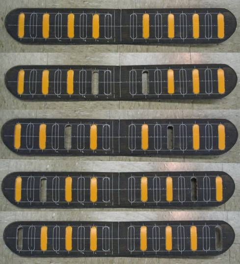
GRW_MAV06_Conference, 2006

                                                     Engineering Parameter Correlation

                                                                                    Benchmarking

                       Figure 1. House of Quality for Gust Resistant Wing Problem

2. Design Methodology:                                   process by providing a comprehensive list of
      This section discusses the design methods          engineering parameters and their coupled effects
adopted for the gust resistant wing problem. The         on other engineering parameters and each
first step in the process was generating a House         customer need.
of Quality to determine the important customer
needs and engineering parameters (specifications         2.2 Transformation Design Methodology:
or requirements) quantifying these needs. This                During the summer of 2006, the research
was followed by implementation of a                      team implemented a new design methodology
Transformational        Design     Methodology,          specifically developed to facilitate the creation of
previously developed under an AFRL grant,                systems with the ability to transform from one
which will be described later.                           state to another in order to facilitate new
                                                         functionality [1]. In this case the first state
2.1 House of Quality:                                    would be the normal flight configuration of the
    The customer needs for this problem were             MAV and the second state would be one that has
gathered from AFRL, special operations troops            enhanced ability to mitigate gusts. This
and research on current developments in the field        methodology incorporates many of the design
of UAVs and MAVs. Engineering parameters                 tools in the state-of-the-art product design
were generated as a result of background                 processes [7], but also includes significant new
research done in aerodynamics of these aircraft.         features. As seen from Figure 3, the method
Figure 1 shows the house of quality relating             incorporates a list of different missions/
needs to engineering parameters. The team                scenarios in which the systems must function.
compiled a list of 35 engineering parameters             Customer needs related to each mission are
(specifications or requirements) that quantify the       gathered and are then combined to form a
important      customer      needs      gathered.        comprehensive customer needs list. Customer
Benchmarking was done with the TACMAV,                   needs were gathered and analyzed through
AV RQ-11 Raven Hawk, AV Black Widow, and                 officials at AFRL and special operations troops.
LM Desert Hawk. This tool helped the team in             The most critical overarching customer need was
decision making through the course of the design         mitigating gust effects on video quality.

                                                     2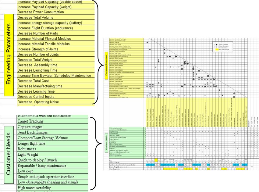
GRW_MAV06_Conference, 2006

                                      X                                 =

                  Figure 2. Transformation Methodology Software Input and Calculation

  Figure 3. Software Result Listing Importance of Capabilities in Each Mission and Across All Missions

Overall 6 degrees of freedom control of the             how many capabilities and needs were listed.
MAV was a distant second broad need. It was             Through a series of matrix math, a Mission vs.
stated that GRW technologies should be                  Mission matrix and Capabilities vs. Capabilities
implement able on the TACMAV (current MAV               matrix is produced in an Excel spreadsheet. This
used by the Special Operations forces) but              information tells the engineer what capabilities
should be applicable to other MAVs as well.             are most important to each individual mission
Capabilities, high order solutions which are not        and all the missions combined. The three
form specific, are then listed that cater to each       highest scoring capabilities (Fig. 3) were counter
customer need. The software creates a matrix for        gust thrusters, changeable camber, and wing
Customer Needs vs. Mission and Capabilities vs.         damping through increased dihedral. The
Customer Needs which are given importance               Transformational Design Methodology software
rating on a scale of 1 ~ 5; 1 being not important       used in conjunction with Transformation Design
and 5 being highly important. The number of             Principle and Facilitators [6, 8] produced a wide
cells that need a subjective input from the             variety of potential concepts for gust resistance.
engineer can be as high as 1700, depending on           A subset of these concepts can be seen in Figure

                                                    3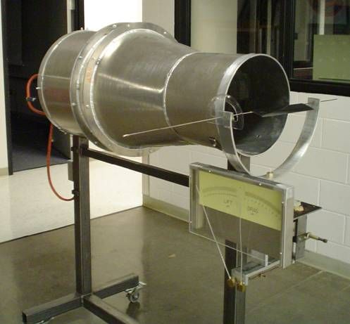
GRW_MAV06_Conference, 2006
4. Three of these concepts were determined to in 1920s [10]. With flaps incorporated into the
be of primary interest in this first iteration of trailing edge of aircraft and the slotted wing
GRW development. The three chosen concepts design in the leading edge, aircraft were able to
include a) Ports in the wings, b) Elastically generate lift and laminar flows on the wing at a
hinged spoilers and c) Variable dihedral angels steep angle of attack (AoA). This also allowed
between the fuselage and wings. for shorter landing and take off while not stalling
at a high AoA for aircrafts flying at high speeds.
Trap Door Wing Some aircraft, like the A-4 Skyhawk and Helio
o Air brake (hole in wing)
Currior have passive leading edge slats. The
Window Blind Wing
o Opens up wings to let gust through ports described in the concept have a function of
Hang Glider reducing lift rather than increasing it and have a
o Changes planform area low speed application. Figure 5 shows a concept
Flying Thruster of the ported wing. The ports shown mitigate
Piezoelectric Wings/Actuators
o Change wing shape
gusts that produce a large change in lift, where
Anhedral the gust is usually a change in vertical air
Dihedral velocity, resulting in a change in angle of attack
Ferromagnetic Veins in Wings (AoA) of the wing (vector sum of the gust from
o Flexible wings
beneath the wing and the relative wind
o Magnetic repulsion gets stronger
“Batwing” encountered by the wing). Ports can act
Coupled wings somewhat as spoilers to create separated flow on
o Springs attached the wing, thus reducing lift.
Active camber
o Wing spires
Counter thrusters Servos Trap Door
o Connect to control inputs to sense
desired movement
Hairy wing
o Electric response polymers
o Variable surface roughness
Tail wing adds to planform area
Figure 4. Subset of Concepts Developed For
GRW
2.3 Concepts for Gust Resistant Wing:
The following sections will detail the Figure 5. Ported Wing Concept
developments and preliminary results of “Ported
Wing Concept”. In addition, the other two 2.3.2. Elastically hinged spoilers:
concepts (“Elastically Hinged Spoilers” and In this concept 3-5 separate segments of the
“Variable Dihedral”) will be briefly described as trailing edge spoiler are located along the length
well. As the goal of the initial stage of the GRW of the wing (Fig. 6). The segmented spoilers are
project is to build a working prototype for the approximately ¼ of the chord in width. This is
MAV competition held at Eglin, Florida in implemented on a very thin carbon fiber wing
October, this initial concept selection process (see the section on airfoil selection below). The
included preference for concepts that were purpose is the same as the “ported wing”
determined to be implement able in a relatively concept, to dump the additional life that a
short time frame. Carbon fiber has been used to vertical gust creates. This method takes
manufacture concept wings and fuselage based advantage of the increase in hinge moment on a
on the needs of strength, stiffness and weight. plain flap with an increase in angle of attack (or
a vertical gust), and also the (small) increase in
2.3.1. Ported Wing Concept: dynamic pressure increasing the hinge moment,
The Ported Wing concept employs the deflecting the flap, and reducing the lift. In this
design of wings with open sections (holes) in the concept the flaps should not deflect as speed
airfoil. These ports are present to reduce the changes at 1g, as the load and therefore the hinge
unwanted lift experienced by the wing due to moment is relatively constant versus speed at 1
wind gusts. This concept differs from slotted g. This is facilitated by an elastic hinge tab
wing [9, 10] on the effect of its application. mounted at the hinge point of the flap. The lift
Slotted wings were first created and introduced dumping characteristics of this concept are
4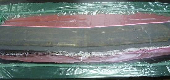
GRW_MAV06_Conference, 2006

facilitated by two factors. First, when the                 3.3).    Actual flight tests involved various
dynamic pressure on the lower edge of the airfoil           iterations and modifications resulting from wind
becomes great enough to overcome the force of               tunnel test data.
the elastic hinge tab, the flap rotates which in
effect “removes” that section of the airfoil
depleting its lift generation. In addition, a small
amount of the vertical gust can “pass through” in
the slot location, mitigating the increase in lift in
the same manner that the ports employ. This
concept draws similarities to a concept that
incorporated segmented control surfaces on the
trailing edge of its wings [11] created at the
University of Florida.

                                                            Figure 7. Two Pronged Experimentation Method

                                                            3.1 Thin Airfoil Lift Analysis, Similitude &
                                                            Testing:
                                                                 One of the first implementation tasks for the
                                                            GRW project was selection of an airfoil. As is
                                                            described below, two different airfoils have been
                                                            used. The foam core foil used for the ported
                                                            wing concept is described in the following
  Figure 6. Elastically Hinged Spoiler Concept              sections. For the thin airfoil used to test the
                                                            elastically hinged spoilers and the variable
2.3.3. Variable dihedral angels between the                 dihedral, the Goettingen 417A was chosen. The
fuselage and wings:                                         Goettingen 417A is known for being a superior
     This concept is being implemented in                   low speed (low Reynolds number) airfoil for
conjunction with the “ported wing” concept and              very small thicknesses. This is the airfoil
“elastically hinged spoiler” concept. As a                  currently being used on the TACMAV which is
dihedral wing has a tendency to increase stability          used by the Air Force Special Forces. Lift
in many situations, the addition of small dihedral          characteristics for this airfoil are readily
angles should increase the stability and therefore          available on the web. Figure 8 is a depiction of
the effectiveness of the above two concepts.                the airfoil shape.
Here the root of the wing can either be flexible
about the longitudinal axis or can be allowed to
be preset for different fixed dihedral angels.
This should help alleviate change in load factor
due to gusts both in the positive and negative
direction. We are in the process of verifying this
hypothesis.

3. Experimental Approach:
     The experimentation was basically a two
pronged approach (Fig. 7) which consisted of: a)
analytical modeling and wind tunnel and b)
actual flight tests of the planes. The wind tunnel                 Figure 8. Goettingen 417A Airfoil
testing consists of two variations, 1) preliminary
testing a scaled version of the thin airfoil (see the            Using simple vector analysis we were able
airfoil description in sections 3.1 and 3.2)                to determine the change in the angle of attack
extensive testing of a full chord, but reduced              that the airfoil would experience for any given
length section of the wing (see sections 3.2 and

                                                        5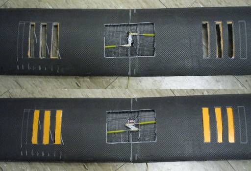
GRW_MAV06_Conference, 2006
gust. This change in angle of attack directly
correlates to a change in lift generated by the
wing. Using the published lift characteristic
data, it was possible to determine this change in
lift. Using the equation:
1
L V 2 C O S Eq. 1
2
we were able to determine how much lift would
be generated both in steady flight and when the
aircraft experiences a gust. This difference in lift
is the amount of lift we need to compensate for,
in optimum gust resistant conditions.
In order to test whether the different
modifications are actually capable of dumping
the required lift, the airfoil is tested in an open
test section wind tunnel. The recorded lift and
drag data is used to determine the ideal Figure 9. Similitude Calculations to Keep Re &
modification solution for the airfoil. Because the Aspect Ratio Consistency
wind tunnel will not allow an airfoil of greater
than 12in., it was necessary to construct smaller Basic testing of the elastically hinged
wings that were fit to scale. In order for these spoilers in the wind tunnel has provided
smaller wings to provide an accurate model of sufficient confidence to continue the pursuit of
actual wing performance it is necessary to this concept. In a 3-spoiler wing, engagement of
maintain Reynolds number (Re) and wing aspect the middle spoiler resulted in approximately 30%
ratio (length/chord) similitude. Reynolds reduction in lift at approximately 100 AoA.
number is a parameter which describes the Engagement of the other spoilers continued the
airflow over a wing. It follows the equation: lift dumping trend. In addition, the elastic hinge,
while not optimized yet, shows promise in being
VC able to maintain the airfoil profile for straight
Re= Eq. 2
and level flight while engaging when significant
vertical gusts occur. Figure 10 shows the open
where is the air’s density, C is the chord
wind tunnel testing facility where the scaled
length, V is velocity, and is the viscosity. versions of the elastically engaged spoilers and
Because the state of the air flowing over the the variable dihedral are being tested. Figure 11
airfoil is one of the most important factors in below shows the hinged region with the full
how much lift the wing generates, it is necessary spoiler engaged as it is set for wind tunnel
to make sure the Reynolds number is the same in testing.
each condition. Since Reynolds number is a
function of both the wing’s cord length and air
velocity, we needed to manipulate the conditions
of our test to match the differing cord lengths
and corresponding velocities so that the scaled
wing and the full size wing experience the same
flight conditions. As can be seen in the screen
capture of the Excel sheet (Fig. 9), if the scaled
wing has a length reduced from 21 inches to 12
inches (this is the max size for the wind tunnel)
then the chord is reduced from 2.375 to 1.357
inches. With this new reduced chord, the scaled
velocity must be increased from 33 ft/sec to 57.8
ft/sec.
Figure 10. Wind Tunnel Used for Testing Scaled
Versions of the Spoiler & Dihedral Concepts
6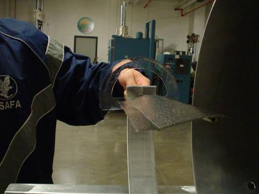
GRW_MAV06_Conference, 2006

                                                          closer to real flight conditions. This is a
                                                          limitation of the wind tunnel experiment detailed
                                                          in this section. Computational Fluid Dynamics
                                                          software FlowWorks was used to generate lift
                                                          and drag data and compute the coefficient of lift
                                                          CL for the airfoil used in the wind tunnel and
                                                          validated the data from the wind tunnel testing.
                                                          Five different orientations were tested:
                                                          rectangular ports at the leading edge of the wing,
                                                          rectangular ports at the trailing edge of the wing,
                                                          rectangular ports along the chord of the wing,
                                                          triangular ports with the base on the leading edge
                                                          of the wing, and triangular ports with the base on
 Figure 11. Scaled Wind Tunnel Tests with Full
                                                          the trailing edge of the wing, (shown in Figures
              Spoiler Engagement
                                                          12(a) through Figure 12(e)). The hypothesis of
                                                          the experiment was threefold - the ports along
     The testing process for the variable dihedral
                                                          the leading edge would decrease the lift more
has just begun. We have created a fixture that
                                                          than those at the trailing edge; drag would
will allow for attachment of wings at variable
                                                          decrease with the addition of holes or ports in the
dihedral angels from 0 deg. ~ 10 deg. Although
                                                          wing; and turbulence would significantly
the justification for pursuit of this concept is
                                                          increase due to air flow disruption by the ports.
purely theoretical at this point, we maintain
                                                          The results of these configurations were to be
sufficient    confidence    to    continue     the
                                                          compared to the same 10in. section of wing
development of the MAV system for flight
                                                          without any holes
testing.
                                                          3.2.1 Experimental Set-Up and Procedure:
3.2 Wind Tunnel Testing and CFD for the
                                                          The wing test sections were constructed from
Ported Wing Concept
                                                          OEM J-3 Cub wings manufactured by ParkZone
     The purpose of the experiment was to
                                                          which closely resemble the specifications of a
determine the effect on the lift and drag forces of
                                                          standard NACA 8305-95 airfoil with a chord
a wing with various cut-out sections or ports
                                                          length of 5.6 inches. Each test section had a
within the wing. The wing used a full-scale
                                                          span of 10in. (full ½ span of the actual wing is
chord, so the experiment and result obtained are
                                                          about twice this). All of the various ports had the
valid for a 2 dimensional analysis [12]. An actual
                                                          same area – 3.8in.2 (approximately 7% of the
scaled down model would however have
                                                          total wing area). Two ports, symmetric to the
captured the effect of trailing vortices created by
                                                          center of the wing, were cut with a scalpel
the wing and results obtained would have been

                                           Wind

    Figure 12(a). Rectangles Along Leading Edge             Figure 12(b). Rectangles Along Trailing Edge

 Figure 12(c). Rectangles Along
             Chord                     Figure 12(d). Triangle Base Along    Figure 12(e). Triangle Base Along
                                                 Leading Edge                         Trailing Edge
               Figure 12. Different Configurations of Ports Cut Out for Wind Tunnel Testing

                                                      7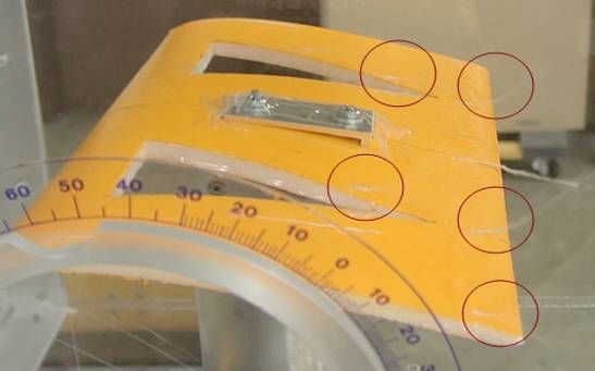
GRW_MAV06_Conference, 2006

(removing 14% of the total wing area). In order          for such drastic difference is most likely due to
to smooth the surface of the cut, clear adhesive         the turbulent flow caused by the ports. Figure 14
tape was placed on the inner faces of the holes.         shows the full wing section at an angle of attack
Short lengths of white cotton twine were also            of 10 degrees. The white twine indicates that the
affixed with adhesive tape along various                 flow is reasonably laminar. On the other hand,
locations of the wings to visualize the air flow         Figure 15(a) shows the wing section with
along the wings.                                         rectangular ports on the leading edge also at a 10
     The tests were conducted in a 12in. x 12in.         degree angle of attack. The white twine is
wind tunnel. The wings were mounted to a force           moving erratically; hence, the flow is more
balance that contained two independent load              turbulent than in the pervious case. The fitful
cells to measure lift and drag forces. Modeled           flow pattern is difficult to photograph; therefore
after anticipated flight characteristics of a            red circles have been drawn around the twine to
modified ParkZone J-3 Cub, all of the trials were        emphasize the location of the twine lengths.
performed at a wind speed of 32mph. The force                 The orientation with rectangular ports along
balance interfaced with a servo motor that               the trailing edge of the wing demonstrated lift
allowed on-the-fly transitions for the angle of          and drag trends most similar to the full wing.
attack. Thus, measurements of lift and drag were         Referring to Figure 13a), the lift trend closely
obtained for angles of attack ranging from 0 to          mimics the full wing, while the lift values are
25 degrees (in increments of 2.5 degrees) for            significantly lower. At an angle of attack of 10
each wing section. Photographs were taken at 0,          degrees, which is approximately the level flight
10, and 25 degrees to record the flow                    angle of attack for the plane, the lift is reduced
visualization produced by the cotton twine. The          by 30%. This is the lowest reduction in lift for
trials were randomized and replicated twice.             the given port area.

3.2.2 Wind Tunnel Test Results:
     The unmodified full wing test section
exhibited the highest lift trend; however, all but
one of the wings with ports showed significant
reductions in drag. Figures 13(a) and 13(b)
show plots of the average values of lift and drag,
respectively, for each wing relative to angle of
attack. On these two graphs, the plot pertaining
to the wing with rectangular ports at the leading
edge (indicated by the magenta line) shows the             Figure 14. Full Wing Section at 10 deg AoA
most deviated trends of lift and drag. The reason

                Figure 13. (a) Lift vs. AoA Curve (b) Drag vs. AoA curve for Various Ports

                                                     8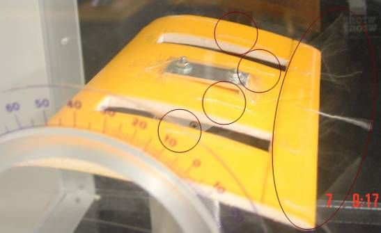
GRW_MAV06_Conference, 2006

                                                         and trailing edge, Figures 17(a) and 17 (b) show
                                                         the flow visualization of the wings having
                                                         triangular ports with bias on the leading edge and
                                                         trailing edge, respectively. The turbulent flow
                                                         reduces lift drastically, but this type of flow also
                                                         causes the lift to be highly varied.

 Figure 15(a). Rectangular Leading Edge at 10
                   deg AoA

                                                              Figure 16. L/D Curves for Various Port
 Figure 15(b). Rectangular Trailing Edge at 10                            Configurations
                   deg AoA

      The main reason for the least reduction in
lift relies on the principle that most of a wing’s
lift is generated toward the leading edge of the
wing. Since this portion of the wing is left
unchanged, less drastic lift characteristics are
expected to be observed. The wing section with
rectangular ports at the trailing edge also
exhibited fairly laminar flow at a 10 degree angle
of attack (Fig. 15(b)), which further supports
why the least amount of lift was lost.                   Figure 17(a). Triangular Leading Edge Biased at
Additionally, the trailing rectangle orientation                           10 deg AoA
provided the least amount of drag (at an angle of
attack of 10 degrees) compared to all other test
orientations (Fig. 13(b)). The combination of
highest lift force and lowest drag force yields
this orientation to be the most efficient when
compared to the other ported wings. Figure 16
displays the efficiency curves for all the wings
tested.
      It is important to note that both triangular
orientations, similar to the orientation with
rectangular ports at the leading edge, reveal lift
profiles quite different than the full wing at           Figure 17(b). Triangular Trailing Edge Biased at
angles of attack between 0 deg and 15 deg. All                             10 deg AoA
three of these port layouts caused the wing
section to vibrate highly and demonstrated                    The wing section with rectangular ports
instability on the force balance. While Figures          along the chord had aerodynamic characteristics
15(a) and 15(b) show the flow visualization of           falling in the median of the experimental data
the wing with rectangular ports on the leading           (Figures 13(a), 13(b) and 16).           Flow

                                                     9
GRW_MAV06_Conference, 2006

visualization for this wing section, shown in                 Table 2. % Change in Lift Comparison of Two
Figure 18, was turbulent at the trailing edge.                          Wing at Different AoA’s
However, several of the lengths of twine
illustrated highly laminar flow while the others
were simultaneously turbulent. This variation in
flow patterns most likely lead to the mid-ranged
lift and drag values. Field tests demonstrate the
possible effectiveness of this port layout; thus
further experimentation is desired. Figure 13(a)
illustrates how this particular orientation has a
higher reduction in lift at 10 degrees compared to
other orientations. If drastic reductions in lift are
                                                             acting on the wing by increasing the AoA
needed for gust mitigation, this orientation
                                                             experienced by the wing. The “Full Wing” can
would be a viable candidate.
                                                             be assumed to be flying at 5 deg AoA and the
                                                             “Rectangular Trailing Edge Port Wing” at 8 deg
                                                             AoA, where both wings maintain at least 3.9 N
                                                             of lift for sustained flight. The AoA shown in
                                                             Table 1 are in increments of 5 degrees. Table 2
                                                             shows us the % increase of both the wings at
                                                             varying AoA’s. It can be clearly seen that the
                                                             “Rectangular Trailing Edge Port Wing” analyzed
                                                             here shows significant lift reduction compared to
                                                             the “Full Wing”. For example at +10 deg of AoA
                                                             there is a 105 % increase in lift generated by the
                                                             “Full Wing” compared to 51% lift generated by
 Figure 18. Chord Spanning Port at 10 deg AoA                the ported wing. Also the % increase in lift of the
                                                             ported wing is lower than the full wing, while
     Assume that the MAV weighs about 400                    maintain lower drag (Figure 13(b)) indicating
grams. The minimum lift required to be                       potential for decreasing lift more steadily
generated for straight and level flight would be             compared to a normal wing. This configuration
approximately 3.9 N. From the lift graph in                  of rectangular ports on the trailing edge appears
Figure 13(a) we can compare the lift                         to have tremendous potential as a GRW.
characteristics of the “Full Wing” (Fig. 14) and
the “Rectangular Trailing Edge Port Wing” (Fig.              3.3 Field Flight Test of Ported Wing:
15(b)). Table 1 and 2, shown below, give us                       The field tests of the ported wing concept
some interesting results. The effect of gust                 were carried out concurrently with the wind
(coming vertically from under the wing) can be               tunnel tests. Some results of wind tunnel testing
modeled as a vector sum with the relative wind               were explored during the field tests and
                                                             subsequent results of the field tests will be
                                                             carried out in the wind tunnel such as changing
Table 1. Effect of Varying AoA on “Full Wing”                the area of ports.
              and “Ported Wing”
                                                             3.3.1 Manufacture of Ported Wings:
                                                                  The ported wings were manufactured
                                                             through Vacuum Bagging (Fig. 19(a)) using
                                                             foam core wings, available commercially, which
                                                             were wrapped with one ply of uni-directional
                                                             carbon fiber (fibers running along the wingspan).
                                                             The addition of carbon fiber gives more
                                                             flexibility in the creation of the ports along the
                                                             wingspan as the carbon fiber provided strength
                                                             to the wing. The wing was then marked with a
                                                             1in. x 1in. grid (Fig. 19(b)) for port size and
                                                             location. The port shapes tested were “Chord
                                                             Spanning Ports” (Fig. 20). Each port represented

                                                        10
GRW_MAV06_Conference, 2006
2% of the total wing area. A total of 8 ports plane generates more lift when the ports
(yellow) were cut into the wing, 4 on each side are at the tips compared to when the
of the wing at increments of 2in. from the center ports are near the fuselage.
of the wing. b) The rolling moment experienced is
more when the ports are near the
fuselage because the moment generated
is from the lift at the wing tips, which is
now more pronounced. When the ports
are towards the wing tips, the lift at the
tips is lower and hence low rolling
moment is experienced.
Figure 19(a). Vacuum Bagging Lay Up
Figure 19(b). Grid Marked on Carbon Figure 21. Field Test Video Images
Fiber Wing for Port Size and Location
These preliminary field tests have given us
valuable insights on the design and location of
these ports. Subsequent field test iterations will
include testing of the “rectangular trailing edge”
ports which seemed a promising port shape and
location from the wind tunnel test. Work on
making wings with semi-active ports is also
being concurrently carried out to test the
actuation of ports during flight (Fig. 22). The
wings are being made of carbon fiber and have a
servo embedded at the center that actuates ports
on either side. The semi-active wing will be
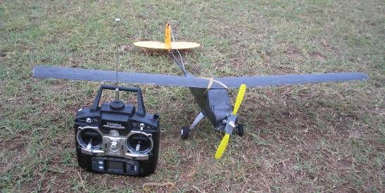
tested on new plane platform shown in Figure
23; the body of which is made of carbon fiber to
make it light weight and more robust.
Figure 20. Chord Spanning Ports Along the
Wingspan
3.3.2 Field Test Results:
From the field tests (Fig. 21) it was seen that
as the ports went inward i.e. towards the fuselage
the plane would experience less lift and would
tend to have a rolling moment and oscillate
during turns. The plane was stable and didn’t
loose as much lift (comparatively) when the Figure 22. Semi-Active Port Actuation
ports were towards the wing tips. There are two
main reasons to this occurrence: 4. Conclusion:
a) The lift generated across the wingspan MAVs are low-weight, small wing span RC
is the greatest near the fuselage. This aircraft. Both civilian and military customers
distribution is well know and is use these MAVs for surveillance. As this
approximately elliptical. Therefore, the surveillance is accomplished through the use of
11GRW_MAV06_Conference, 2006
on-aircraft video cameras, the stability of the the wing chord. This will be carried out in the
aircraft is critical to obtaining quality video wind tunnel as well as in actual flight tests. The
images. Windy environments often make this motivation this is that the trailing edge rectangles
video virtually un-usable. In light of this performed well in the previous experiments,
scenario, the development of wing technology while field test have proven that rectangular
that can resist wind gusts is critical. ports along the chord fly well. The experimental
data on these ports show even more reduction in
lift at 10 deg angle of attack with only moderate
turbulent flow across the wing surface. The next
phase of experimentation will provide optimal
port orientations and areas, validated through
successful implementation of this concept and
test flight to demonstrate vertical gust mitigation
of MAVs.
Experiments on the elastically hinged
spoilers are also continuing. Different numbers
Figure 23. New Testing Platform of spoilers as well as different hinge stiffness are
among the critical variables. Both wind tunnel
A newly developed Transformational and flight testing is in progress for this concept.
Design Methodology (used to design systems Similarly, the testing for the variable dihedral is
that change state in order to facilitate new also continuing. The variable dihedral concept is
functionality) has been implemented to produce scheduled to be implemented in conjunction with
concepts intended to mitigate gusts. Three the other two concepts to determine if it will
concepts in particular have been identified for produce the hypothesized increase in stability.
continued testing. These concepts are 1) Ported
Wings, 2) Elastically Hinged Spoilers and 3)
Variable Dihedral. Each of these concepts has
Acknowledgements
The authors would like to acknowledge the
been investigated both in wind tunnel testing and
support provided from the Cullen Endowed
through the use of actual flight tests. In
Professorship in Engineering, The University of
particular, the ported wing concept has been
Texas at Austin, and grants from the Air Force
extensively tested resulting in confidence that
Research Laboratory Munitions Directorate
this concept is implementable and effective at
(AFRL/MN) at Eglin, Florida and the Air Force
mitigating the effects of gusts. For example,
Office of Scientific Research (AFOSR). The
rectangular ports located close to t he trailing
authors would also like to thank the Department
edge of he airfoil have been shown to reduce the
of Engineering Mechanics at the U.S. Air Force
lift associated with vertical gusts (modeled as
Academy for their support and guidance. The
increasing AoA) by as much as 50% while
authors would like to extend their thanks to Dr
actually reducing drag. The concept of
Robert Sierakowski, Dr. Greg Abate, Mr. Chris
elastically hinged spoilers also appears to have
Perry, Lt. Aaron Sand and Mr. Ken Blackburn in
promise in the ability to “dump lift” in the
AFRL/MN at Eglin, Florida for their guidance at
presence of vertical gusts.
various stages of development of this project.
Any opinions, findings, or conclusions found in
4.1 Future Work:
this paper are those of the authors and do not
Future experiments will be done with
necessarily reflect the views of the sponsors.
various port areas. These experiments will focus
on the orientation with rectangular ports along
the trailing edge and the rectangular ports along
References:
[1] Tang, D., Dowel, E. H., 2002, “Experimental and Theoretical Study of Gust Response for High-Aspect-
Ratio Wing”, AIAA Journal, Vol. 40, No. 3
[2] Patil, M. J., 2006, “Gust Response of highly Flexible Aircraft”, 47th AIAA Structures, Structural
Dynamics, and Materials Conference, Newport, Rhode Island
[3] Pettit, C. L., Grandhi, R. V., 2003, “Optimization of a Wing Structure for Gust Response and Aileron
Effectiveness”, Journal of Aircraft, Vol. 40, No. 6
12GRW_MAV06_Conference, 2006
[4] Garcia, H., Abdulrahim, M., Lind, R., 2003, “Roll Control for a Micro Air Vehicle using Active Wing
Morphing”, AIAA Guidance, Navigation and Control Conference
[5] Ro, K., Kamman, J. W., Barlow, J. B., 2005, “Flight Performance Analysis of Freewing Tilt-BodyTM
Unmanned Aerial Vehicle”, AIAA Atmospheric Flight Mechanics Conference and Exhibit, San Francisco,
California
[6] Singh, V., Skiles, S., Krager, J., Wood, K., Jensen, D., Szmerekovsky, A., 2006, “Innovations in Design
Through Transformation: A Fundamental Study of Transformation Principles, International Design
Engineering Technical Conferences, Philadelphia, PA
[7] Otto, K., Wood, K., 2001, “Product Design: Techniques in Reverse Engineering and New Product
Development”, Prentice-Hall, New Jersey
[8] Skiles, S., Singh, V., Krager, J., Seepersad, C., Wood, K., Jensen, D., 2006, “Adapted Concept
Generation and Computational Techniques for the Application of A Transformer Design Theory”,
International Design Engineering Technical Conferences, Philadelphia, PA.
[9] Klemperer, W., 1922, “Problem of the Slotted Wing”, A Communication from the Aerodynamic
Institute of the Aachen Technical High School, Technical Memorandum, National Advisory Committee for
Aeronautics
[10] “Slotted Wings, Flaps, and High Lift Devices”,
http://www.centennialofflight.gov/essay/Evolution_of_Technology/High_Lift_Devices/Tech6.htm,
September 2006
[11] Abdulrahim, M., 2003, “Flight Dynamics and Control of an Aircraft with Segmented Control
Surfaces,” AIAA 54th Southeastern Regional Student Conference, Kill Devil Hills, NC
[12] Houghton, E. L., Carpenter, P. W., 2003, “Aerodynamics: For Engineering Students”, 5th Edition,
Butterworth-Heinemann, Burlington, MA
13You can also read