A REVIEW OF AERONAUTICAL FATIGUE INVESTIGATIONS IN FINLAND APRIL 2011 - FEBRUARY 2013 - VTT
←
→
Page content transcription
If your browser does not render page correctly, please read the page content below
NATIONAL REVIEW 13                         ICAF Doc   2428                     3.4.2013

           A REVIEW OF AERONAUTICAL FATIGUE
               INVESTIGATIONS IN FINLAND
                APRIL 2011 – FEBRUARY 2013
                                                      rd
                                 Presented at the 33 Conference of the
                         International Committee on Aeronautical Fatigue and
                                      Structural Integrity (ICAF),
                                    Jerusalem, Israel, 3-4 June 2013

       Compiled by                Aslak Siljander

       Confidentiality            Public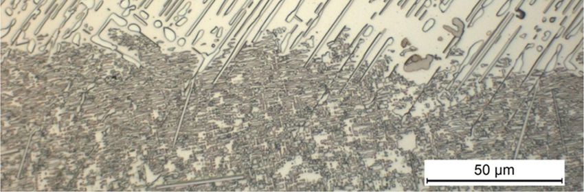
National Review 13 / 2 (50)

Preface
The Finnish Air Force Materiel Command (FINAFMC), Programmes Division, initiated and supported this
work. The editor is indebted to the following individuals who helped in the preparation of the review
(organizations and individuals in alphabetical order – the reference list refers to paragraph-specific
contributions):

Aalto                  Aalto University, School of Engineering, Department of Applied Mechanics, Aeronautical
                       Engineering: Jarkko Aakkula, Olli Saarela, Markus Wallin;
Emmecon                Emmecon Ltd: Risto Hedman;
FINAFMC                Finnish Air Force Materiel Command, Programmes Division: Mikko Järvinen, Ari Kivistö,
                       Kari Renko, Kalle Vaaraniemi, Ari Välikangas;
                       Finnish Air Force Materiel Command, Plans Division: Henry Paajanen;
                       Finnish Air Force Materiel Command, Aircraft Division: Jukka Taattola;
FINAFFTC               Finnish Air Force, Flight Test Center: Raimo Enberg, Hannu Heinelo, John Öström;
FINAFLAC               Finnish Air Force, Lapland Air Command: Teemu Tuovila;
FINAFKAC               Finnish Air Force, Karelian Air Command: Kari Kilkki;
FINAFSAC               Finnish Air Force, Satakunta Air Command: Peter Ylinen;
Finflo                 Finflo Ltd: Juho Ilkko, Esa Salminen, Timo Siikonen;
Millidyne              Millidyne Ltd: Mika Kolari, Petri Sorsa;
Patria                 Patria Aviation Oy, RTD & Aeronautical Engineering: Toivo Hukkanen, Mika Keinonen,
                       Mirve Liius, Janne Linna, Simo Malmi, Antero Miettinen, Mikko Orpana, Jouni Pirtola,
                       Jukka Raunio, Tuomo Salonen, Jaakko Sotkasiira, Maria Stenberg, Piia Stenhäll,
                       Jarkko Tikka;
                       Patria Aviation Oy, Systems / Avionics: Juha Alanko, Jari Koivu, Maunu Mäntylä, Marika
                       Vuori, Lauri Walden;
                       Patria Aviation Oy, Aircraft, Engines Unit: Jani Simelius;
TUT/DSP                Tampere University of Technology, Department of Signal Processing: Juha Jylhä, Marja
                       Ruotsalainen, Ari Visa;
TUT/DMS                Tampere University of Technology, Department of Materials Science: Elina Huttunen-
                       Saarivirta, Turi Salomaa, Veli-Tapani Kuokkala, Viivi Pirttiniemi;
TUT/IHA                Tampere University of Technology, Department of Intelligent Hydraulics and Automation:
                       Jussi Aaltonen, Vänni Ala-Rotu, Kari T. Koskinen;
VTT                    VTT Technical Research Centre of Finland: Pertti Auerkari, Harri Janhunen, Petra
                       Jauhiainen, Juha Juntunen, Keijo Koski, Arto Kukkonen, Risto Laakso, Kari Lahdenperä,
                       Esa Leskelä, Sauli Liukkonen, Johanna Lukin, Juha Mannila, Sakari Merinen, Juha
                       Nikkola, Arto Nyholm, Tauno Ovaska, Enna Peltoniemi, Juhani Rantala, Eetta Saarimäki,
                       Jorma Salonen, Matti Sarkimo, Jarmo Siivinen, Aslak Siljander, Laura Sirkiä, Tuomas
                       Teittinen, Piritta Varis, Päivi Varis, Esa Varis, Juha Veivo, Tomi Viitanen, Sanni Yli-Olli.

Espoo 3rd April 2013

Editor
National Review 13 / 3 (50)
Contents
13.1 Introduction .....................................................................................................................4
13.1.1 Valmet Vinka ........................................................................................................................ 5
13.1.2 Hawk Mk51/51A and Mk66 .................................................................................................. 6
13.1.3 F-18C/D Hornet..................................................................................................................... 7
13.1.4 Scope of the review ............................................................................................................... 9
13.2 Current activities: ASIMP 2010-2012 and ASIMP 2013-2016...................................... 10
13.2.1 Loads and stresses ............................................................................................................... 10
13.2.1.1 Computational fluid dynamics (CFD) – update ................................................................ 10
13.2.1.1.1 Flow simulations for NH90 helicopter fuselage with an actuator disc ......................... 10
13.2.1.1.2 Computational Fluid Dynamics activities at Finflo Ltd............................................... 12
13.2.1.1.3 Initial value provisions for the F-18 CFD analyses ..................................................... 13
13.2.1.2 Flight simulations ........................................................................................................... 14
13.2.1.3 Hornet FE modeling – update .......................................................................................... 15
13.2.2 Fatigue tracking systems ...................................................................................................... 16
13.2.2.1 FINAF F-18 HOLM jets in routine squadron service ....................................................... 16
13.2.2.1.1 Vertical tail measurements of International Mini-HOLM flights ................................. 17
13.2.2.1.2 HOLM modification .................................................................................................. 17
13.2.2.2 Flight maneuver identification (FMI) – update................................................................. 18
13.2.2.2.1 Fatigue damage of nominally similar flight maneuvers ............................................... 19
13.2.2.2.2 Reasoning flight parameter based rules that explain the degree of damage .................. 20
13.2.2.3 Parameter based fatigue life analysis - update .................................................................. 21
13.2.2.3.1 Updated results (CFD – FEA – transfer functions) ..................................................... 21
13.2.2.3.2 In-service maintenance .............................................................................................. 23
13.2.2.3.3 Add in new structural locations and future plans ........................................................ 24
13.2.2.4 Research efforts towards an OLM replacement system (Hawk Upgrade 2) ....................... 24
13.2.2.4.1 Structural health monitoring (SHM)........................................................................... 24
13.2.2.4.2 Integrated eddy current inspection system for FINAF Hawks ..................................... 24
13.2.3 Structural integrity of composite materials ........................................................................... 25
13.2.3.1 Thermographic studies – update ...................................................................................... 25
13.2.3.2 Fracture mechanics based analysis and tests of delaminations .......................................... 27
13.2.4 Structural integrity of metallic materials............................................................................... 29
13.2.4.1 FISIF Hole Salvage project ............................................................................................. 29
13.2.4.2 Non-destructive inspection (NDI) activities (metallic materials)....................................... 30
13.2.4.2.1 Experimental study of the sensitivity of the crack detection techniques applicable in the
periodic in-service inspections using painted test specimen with real fatigue cracks. ...................... 30
13.2.5 Repair technologies ............................................................................................................. 33
13.2.5.1 Repair technologies for composite structures ................................................................... 33
13.2.5.1.1 Aircraft battle damage repair of composite structures ................................................. 33
13.2.5.2 Repair technologies for the FINAF F-18 metallic primary structures ................................ 34
13.2.5.2.1 DIARC plasma coating for reliable and durable structural bonding of metals.............. 34
13.2.5.2.2 Computational fatigue life assessment of a metallic structure with a bonded composite
repair 36
13.2.6 Mechanical systems integrity ............................................................................................... 38
13.2.6.1 Simulation and modeling................................................................................................. 38
13.2.6.2 Laboratory testing ........................................................................................................... 38
13.2.6.3 Condition control and monitoring .................................................................................... 38
13.2.7 Engine integrity ................................................................................................................... 39
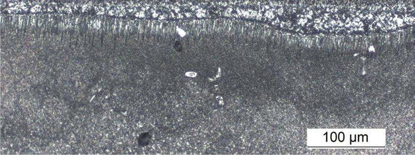
13.2.7.1 Microstructural degradation of a single-crystal gas turbine blade...................................... 39
13.2.7.2 Guideline - turbine blade failures..................................................................................... 40
13.2.7.3 The effect of volcanic ash on gas turbine blades and vanes............................................... 42
13.2.7.4 The effect of volcanic ash on gas turbine vanes................................................................ 43
13.3 Related activities ............................................................................................................ 44
13.3.1 Environmentally friendly corrosion protection studies .......................................................... 44
13.4 References ...................................................................................................................... 46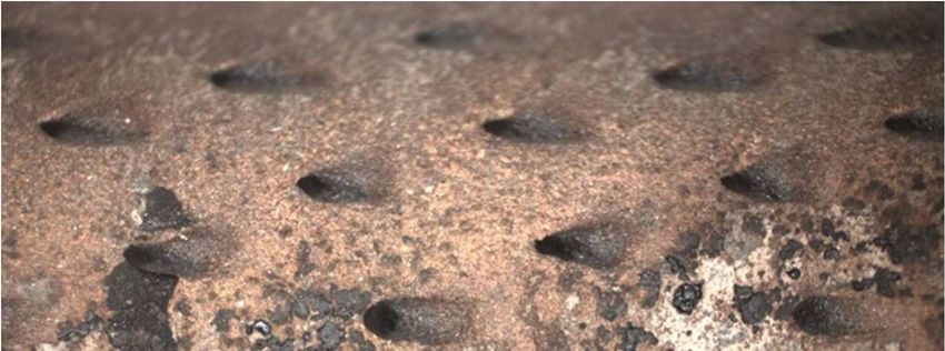
National Review 13 / 4 (50)

   13.1        Introduction
            The year 2013 marks the 95th anniversary of the Finnish Air Force (FINAF) – one of the oldest
            independent air forces in the world. It was founded as an independent service on the 6th March
            1918 [1]. The fixed wing aircraft inventory of the FINAF at the time of writing this review is
            summarized in Fig. 1. The third C295M was received in 2011. The PC-12NG aircraft have
            replaced the six (6) twin-engine Piper Chieftains, which were 25 years in the FINAF operation.
            The Chieftains were retired in 2011. Ten (10) Valmet Redigos will be retired, one by one, by the
            year of 2013.

Figure 1:   An overview of the fixed wing aircraft inventory of the Finnish Air Force (FINAF). Picture by
            courtesy of the FINAF.

            By the end of year 2012, of the 20 TTH/SAR NH90 helicopters purchased by the Finnish Defence
            Forces (FDF), a total of 15 helicopters have been assembled by Patria. Five of the received
            NH90’s are in the initial operational configuration (IOC) and ten in the IOC+ configuration. The
            last five NH90s will be delivered in future and those helicopters correspond to the full operational
            configuration (FOC), while those NH90s delivered earlier will be upgraded to the FOC. The
            helicopters of the FDF at the time of writing this review are summarized in Fig. 2.
National Review 13 / 5 (50)

Figure 2:   An overview of the rotary wing aircraft inventory of the Finnish Defence Forces (FDF). Picture by
            courtesy of the FINAF.

            Before going into highlights of the structural integrity management activities, a brief update of the
            FINAF’s fighter aircraft and associated pilot training aircraft is provided below.

   13.1.1      Valmet Vinka
            Previous activities related to the Valmet Vinka primary trainer of the FINAF were outlined in e.g.
            [2 Chapter 13.1.1]. During the life extension program (LEP) of the Vinka primary trainers, the
            entire fleet was equipped with a g counter. The structural life consumption and severity of the
            usage is monitored by Patria Aviation by using the tail number-specific g counter. Patria also
            issues recommendations on yearly basis regarding the rotation of the Vinka fleet as well as its fleet
            leaders. This is to obtain a more even rate of structural life expended and to keep the fleet leaders
            reasonably ahead of the rest of fleet in flight hours.
            Based on the g counter information, the primary trainers are in good structural condition with
            regard to the flight hours. The severity of usage in view of the g counter status is more benign than
            that on the basis of LEP assumptions, see Fig. 3. It is possible to operate with Vinka until 2020
            under its current type certificate. If there is a need to operate beyond 2020, the Vinka fleet will
            require another LEP.
            All options are being held open when it comes to how the Vinka fleet is going to be replaced in the
            future. A new type of aircraft is one possibility. In addition to that, collaboration with another
            country and buying the training from a company are other possibilities. Currently the FINAF
            procures the primary training from Patria, while the aircraft used in training are owned by the
            FINAF.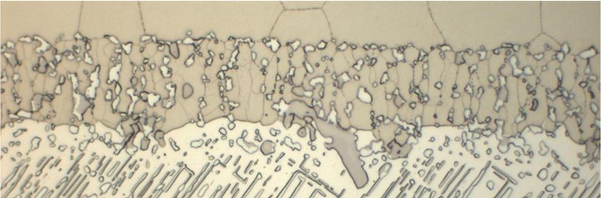
National Review 13 / 6 (50)

Figure 3:   The g counts (x-axis) per 1000 FH (y-axis) of the Valmet Vinka. The spectrum representing the
            LEP design assumptions (LEP-4). The post LEP g counter spectrum as of May 2006 (- x -), as of
            November 2006 (- -), as of December 2007 (- -), as of December 2008 (- -), as of January
            2010 (–•–), as of December 2010 (– –), and the updates from the previous review: as of December
            2011 (- · -) and as of December 2012 (- -). All curves (excluding the red LEP-4) represent the
            fleet average from all Vinkas, as ranked according to the a/c center of gravity normal
            acceleration. Picture by courtesy of Patria Aviation.

   13.1.2      Hawk Mk51/51A and Mk66
            In 2007, the Finnish Air Force purchased 18 pre-owned Hawk Mk.66s from Switzerland. These
            supplemented the Hawk Mk.51/51A fleet purchased earlier. In 2009, this was followed up by an
            order placed with Patria, for an extensive cockpit and avionics upgrade of the aircraft. The upgrade
            includes the replacement of all important avionics devices and cockpit display systems by new
            digital IT systems. The design is based on the upgrade already implemented on Mk.51/51A
            aircraft. Under the current programme, Patria is also responsible for developing software for the
            aircraft’s mainframe, the Mission Computer. During 2011 Patria delivered six (6) and during 2012
            eight (8) modified aircraft to the FINAF. All 18 aircraft will be modernized and delivered during
            2013 [3]. The aircraft which are not modernized will be retired in the coming years. In 2015 all the
            FINAF Hawks will be modernized and the fleet will consist of one (1) Mk.51, seven (7) Mk.51As,
            and 18 Mk.66s.
            The structural fatigue consumption of the FINAF Mk.51/51A Hawks is summarized in Fig. 4.
            Further Hawk-related research efforts are provided in Chapter 13.2.2.4.
National Review 13 / 7 (50)

Figure 4:   G exceedance development of the FINAF Hawks (Mk.51 & Mk.51A) at the end of year 2012 (fleet
            average; data from all 57 aircraft included (excluding the modified Mk.66 aircraft), as ranked
            according to the a/c center of gravity normal acceleration. Note that all of the FINAF Hawks have
            been operating from the Kauhava air base since the end of 2005. Picture by courtesy of the
            FINAF.

   13.1.3      F-18C/D Hornet
            Between 2012-2015, Patria will conduct the Mid-Life Upgrade 2 (MLU2) systems upgrade’s
            series installations for the first 35 FINAF Hornet fighters and related manufacturing of
            components and harnesses. The work will take place in conjunction with scheduled maintenance
            and structural updates of the aircraft. The goal of the FINAF is to upgrade all of its 62 fighters by
            the end of 2016. Patria has earlier implemented the first systems upgrade (MLU1) between 2007-
            2010 and performed the final assembly and testing of 57 single-seat F-18 C models when the
            fighters were purchase [4].
            After the MLU2 upgrade the FINAF Hornets will have the ability to perform air-to-ground
            operations. This will reflect on training programs and the use of the aircraft. Other significant
            upgrades are, for example, the cockpit upgrade with new displays and the BOL countermeasures
            dispensers. There are special arrangements to manage the C and D model differences between the
            USN and the FINAF in the MLU2-induced configurations: The software testing will be done in
            Finland by the FINAFFTC and Patria’s STIC laboratory (Software Test and Integration Centre).
            For the first time in the history of the Hornet, there is a foreign (Finnish) organization approved as
            a part of the approval process of the US software. The MLU2 preparation work is done in co-
            operation with the Swiss Air Force.
            The current structural life consumption of the FINAF F-18 fleet is shown in Fig. 5. As presented
            in the figure, the aircraft usage seems less severe than the design target. However, when compared
            to other F-18 operators the usage is more severe. The current target for the FINAF F-18 aircraft is
            4500 FH and 0.75 FLE (simultaneously).
            It is worth noting that the structural life consumption (Fig. 5) is mainly decided based on a single
            detail of structure. The data collected from the said detail is processed by a piece of software
National Review 13 / 8 (50)

            provided by the aircraft manufacturer. As a result the structural life consumption for each aircraft
            in fleet is given. Recently a new version of the software was taken into use by the FINAF and on
            average the results were lower for structural life consumption than using the previous software
            version.

Figure 5:   Summary of the wing root fatigue life expended (FLE) of the FINAF F-18C/D fleet at the end of
            year 2012. The data is from all 62 aircraft included. The target is 4500 FH and simultaneously
            0.75 FLE. Picture by courtesy of the FINAF.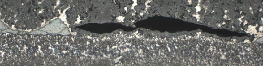
National Review 13 / 9 (50)

13.1.4      Scope of the review
         This national review on aeronautical fatigue concentrates on the fixed wing aircraft inventory of
         the FINAF related to fighter jets and associated pilot training aircraft. The FINAF inventory today
         includes 62 F-18C/D Hornet fighters, 48 Mk.51 Hawk jet trainers (+18 Mk.66 aircraft from
         Switzerland) and 28 Valmet Vinka primary trainers. During the writing of this review,
         approximately 124 000 FH have been flown with the Hornets, 236 000 FH with the Mk.51 and
         Mk.51A Hawks (+20 000 FH Mk.66 Hawks) and 163 000 FH with the Vinkas.
         No FINAF aircraft of these type designations have been lost due to structural issues.
         The severity of the Finnish usage in view of structural fatigue with the two jets of noteworthy
         maneuvering capability can be seen in Fig. 4 (Hawk) and Fig. 5 (Hornet). Figs. 4 and 5 clearly
         demonstrate the need to maintain, further develop and apply concrete and systematic efforts to
         cope with the structural deterioration effects of these two aircraft types.
         During 2005, the International Committee on Aeronautical Fatigue (ICAF) formally welcomed
         Finland as a full member of the ICAF, making Finland the 13th full member. This Finnish national
         review of current aeronautical fatigue investigations up to February 2013 – although the 7th review
         but the 4th review as a full member – was compiled by Aslak Siljander (VTT).
         The review comprises inputs from the organizations listed below (in alphabetical order).

         Emmecon              Emmecon Ltd, P. O. Box 35, FI-53851 Lappeenranta, Finland
                              (http://www.emmecon.fi/)
         FINAFMC              The Finnish Air Force Materiel Command, P. O. Box 210, FI-33101
                              Tampere, Finland.
                              The Finnish Air Force Materiel Command, Programmes Division, Aircraft
                              Section, P. O. Box 14, FI-41161 Tikkakoski; Finland.
                              (http://www.ilmavoimat.fi/index_en.php)
         Finflo               Finflo Ltd, Tekniikantie 12, FI-02150 Espoo, Finland (http://www.finflo.fi/)
         Millidyne            Millidyne Ltd, Hermiankatu 6A, FI-33720 Tampere (www.millidyne.fi)
         Patria               Patria Aviation Oy, RTD & Aeronautical Engineering, FI-35600 Halli,
                              Finland (http://www.patria.fi/index2.htm)
         Aalto                Aalto University, School of Engineering, Department of Applied Mechanics,
                              Aeronautical Engineering, PO Box 14300, Puumiehenkuja 5 A , FI-00076
                              Aalto, Finland (http://appmech.tkk.fi/en/research/research_group1/)
         TUT/DSP              Tampere University of Technology, Department of Signal Processing,
                              Korkeakoulunkatu 1, FI-33720 Tampere, Finland (http://sp.cs.tut.fi)
         TUT/DMS              Tampere University of Technology, Department of Materials Science,
                              Korkeakoulunkatu 6, FI-33720 Tampere, Finland (http://www.tut.fi)
         TUT/IHA              Tampere University of Technology, Department of Intelligent Hydraulics and
                              Automation, P.O. Box 589, FI-33101 Tampere, Finland
                              (http://www.iha.tut.fi/research/aircraft/)
         VTT                  VTT Machine and Vehicle Industries, P. O. Box 1000, FI-02044 VTT,
                              Finland (http://www.vtt.fi/?lang=en)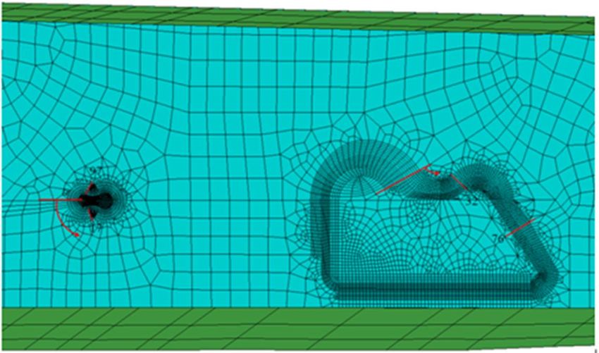
National Review 13 / 10 (50)

   13.2         Current activities: ASIMP 2010-2012 and ASIMP 2013-2016
             The Aircraft Structural Integrity Management Program (ASIMP) 2010-2012, as briefly outlined in
             [4], has been completed. The follow-on program, the ASIMP 2013-2016 with its various sub-
             programs, is about to start. An attempt is provided below to provide highlights of the ASIMP
             2010-2012 achievements, including those from the parallel research programs.

   13.2.1       Loads and stresses

13.2.1.1     Computational fluid dynamics (CFD) – update
13.2.1.1.1   Flow simulations for NH90 helicopter fuselage with an actuator disc
             Previous CFD activities (flow simulations) have been reported in e.g. [4 Chapter 13.2.1.1]. In the
             ICAF 2011 report, time-accurate CFD studies for a helicopter rotor in forward flight were
             described to demonstrate the capability for dynamic rotor studies. Since then, the helicopter CFD
             work has concentrated on modelling the flowfield around the NH90 fuselage to be able to study
             local modification effects and loads related to them. The work has been done in co-operation with
             Finflo Oy, Espoo. For this purpose, a structured multi-block grid [5] was generated around the
             fuselage based on a representative geometric model created earlier at Patria. The grid covers the
             whole asymmetric fuselage with its tail surfaces and contains some of the larger antennas and a
             simplified axisymmetric main rotor hub. Flows through the engine inlets and exhausts are
             specified via boundary conditions. The fuselage grid consists of 99 blocks and has around 17
             million cells.
             As the flow induced by the main rotor plays an important role in the fuselage flowfield, the rotor
             effects are taken into account in the simulations by an actuator disc model [6]. The main rotor is
             represented by an axisymmetric overset grid block that covers the aerodynamic parts of the blades.
             The rotor can be tilted as desired and have a cone angle. On the circular rotor disc plane itself,
             analytical time-averaged distributions of axial, tangential and radial flow forcing actions are
             calculated as functions of the prescribed thrust resultant and flight conditions based on a classic
             rotor theory. The effects are fed into the Navier-Stokes simulations via source terms of the
             momentum and energy equations. The grid block for the disc contains just about 0.33 million cells.
             Test calculations for the NH90 [7] were performed with the domestic RANS-type FINFLO flow
             solver in two conditions representing level flight at 132 kt and hover. The computations aiming at
             steady states by pseudo-time integrations took long times to converge, and the solutions remained
             somewhat oscillatory. This was to be expected, since the helicopter with its rotor hub, exhaust
             stacks and some bulky antennas is not particularly streamlined. Especially the hover case with the
             fuselage perpendicular to the rotor outflow represents the boundaries of meaningful time-averaged
             simulations.
             In cruise at zero angle of attack, the lift of the fuselage is negative and is caused by its shape with
             little rotor influence. The computed lift magnitude corresponds to about 7 per cent of the
             helicopter weight. The fuselage drag is about the same as the horizontal component of the thrust
             vector tilted 4 degrees forward. The results conform to expectations, but there are no real data
             available for validation. The computed flowfield is illustrated in Fig. 6 by the pressure distribution
             on the fuselage, Mach number distribution on the nominal symmetry plane, vertical velocities on
             the rotor plane and by some streamlines.
National Review 13 / 11 (50)
Figure 6: Computed flowfield around NH90 in cruise. Picture by courtesy of Patria Aviation.
In the hover case, the averaged down-force acting on the fuselage and entirely caused by the rotor
blowing again represents about 7 per cent of the helicopter weight, and the horizontal forces are
small. Also the moment balance is reasonably good. Fig. 7 shows the fuselage pressure
distribution and vertical velocity on the rotor plane and on a plane 6 meters below the fuselage. It
is clearly seen that the fuselage disturbs the rotor outflow strongly and the pattern below the
helicopter is far from axisymmetric. On the rotor disc plane, the distortion effects of the fuselage
are also clearly visible
Figure 7: Computed flowfield around NH90 and on a horizontal plane below it in hover. Picture by courtesy
of Patria Aviation.National Review 13 / 12 (50)
13.2.1.1.2 Computational Fluid Dynamics activities at Finflo Ltd.
Computational fluid dynamics (CFD) research at Finflo Ltd. is based on the in-house flow solver
FINFLO. An essential feature of the code is a Chimera method applied in simulating flow fields
around the FINAF F-18C fighter. Basic features of the method are described in [8]. Since then,
significant improvements have made in the algorithm. The Chimera method currently utilizes
accurate wall distances, a refined interpolation method and completely new dominating criteria for
the overlapping grid blocks. The computation of the wall distances is time-consuming, but the
procedure has been significantly enhanced during the recent years. In 2010 a new high-resolution
grid for the F-18C was developed and considerable improvement has been obtained in the
accuracy of the Chimera interpolation in the narrow gaps between the flaps and the wing. The
repetition task of all previously simulated flight conditions using the new grid was completed in
2012.
As a part of the FINAF Hornet Mid Life Upgrade 2 (MLU2) Program, the FINAF is currently
integrating the BOL countermeasures dispensing system (CMDS) from the Swedish defence and
security company Saab on the F-18 Hornet fighter. The BOL CMDS protects the aircraft against
heat-seeking and radar guided missiles. The BOL system uses wing-tip vortices to distribute the
chaff- and IR payload, which improves dispersion and the rapid formation of a protective cloud.
As a part of the integration program, CFD studies were used to estimate the effect of the BOL
cassettes and BOL adapter covers on the shock waves and on the external loads, Fig. 8.
Co-operation with CFSE and RUAG of Switzerland has been continued. Meetings have been
arranged to handle technical aspects and general CFD development. Recently the FINFLO and the
NSMB codes were evaluated by calculating two flow cases at a high angle of attack for the F/A-
18. The results were presented in ICAS 2012 Congress in Brisbane, Australia [9].National Review 13 / 13 (50)
Figure 8: A pressure distribution on a complex F-18C configuration. Clean wing pylon sides (top), modified
wing pylons equipped with BOL adapter covers (middle), and BOL cassette pairs on sides of the
outboard wing pylons and adapter cover pairs on sides of the inboard wing pylon (bottom). Level
flight at Ma=0.95. Picture by courtesy of Finflo Ltd.
13.2.1.1.3 Initial value provisions for the F-18 CFD analyses
One crucial step prior running computational fluid dynamics (CFD) analyses for the aircraft is to
set the aircraft model in question into equilibrium. This can be executed by the recently developed
trim routine [4 Chapter 13.2.1.2.3] or by the OEM’s software. In the given flight condition,
aircraft’s state (flight parameters), control surface deflections and engine properties like net thrust
and exhaust nozzle properties can be obtained as a result of the trimming.
During the last research period VTT supplied initial values to Finflo Ltd. for the CFD analyses of
the Finnish F-18 Hornet. In 8 of 11 cases the aircraft was in so called Fighter Escort configuration
and 3 cases include non-default configurations [10].National Review 13 / 14 (50)
13.2.1.2 Flight simulations
As it has been outlined in e.g. [2 Chapter 13.2.1.2], the flight simulations have been utilized in
various projects to support the structural life management of the Finnish F-18 Hornet aircraft. For
this purpose, the FINAF has continued the funding of the development and maintenance of the
low-cost Matlab/Simulink based flight simulation software called HUTFLY2. The program’s
modular design allows the implementing of different aircraft models into it. Currently the most
important one is the F-18C aircraft model [11 - 14].
In order to maintain the flight simulation results as realistic as possible for the actual FINAF
flying, some upgrades have been implemented into the HUTFLY2 software recently [15, 16].
Among the listed items in [2 Chapter 13.2.1.2] is the Flight Control System (FCS) model which
has been upgraded along the real life counterpart during the last research period [17].
The F/A-18 Flight Control System (FCS) is a fly-by-wire Control Augmentation System (CAS)
whose inner loop has been divided into longitudinal, lateral and directional control law
computations. The control laws are reconfigured for the Auto Flap Up (AFU, up and away flight)
and Power Approach (PA, takeoff and landing) flight phases.
The existing Simulink-model of the HUTFLY2 F-18 Flight Control System (FCS) was upgraded
from the Flight Control Computer (FCC) Operation Flight Program (OFP) version V10.5.1 to
version V10.7 according to the Original Equipment Manufacturer’s (OEM) documentation [17,
18]. The digital inner loop control laws have been modeled as a continuous system instead of the
initial multi-rate discrete version. The upgraded model consists of approx. 5200 blocks, including
sensor models and hydraulic servo-actuator (high order) models. In addition to the Auto Flap Up
flight mode, the Power Approach flight mode has been taken into account but automatic flight
control modes (outer loop), out of control flight mode and degraded flight control modes (i.e.
failure logics) have been excluded from the model because their impact on the structural research
of the Finnish F-18 aircraft is considered to be of minor importance. As an output the FCS model
provides command values for the control surface actuators from the pilot inputs.
The essential phase in the development of the system is verification and validation (ver/val).
Validation is yet to be done. At the moment, verification of the upgraded FCS model includes the
time history comparisons of the given pilot inputs. For example response of the directional control
(i.e. rudder) doublet without aerodynamics can be seen from Fig. 9. From the figure it can be seen
that for the same input, the commanded rudder deflections are smaller in the upgraded FCS
version than in the reference version due to the increased full pedal input departure resistance.
Rate limiters have been remained the same which is manifested by the identical slopes of the
responses.
Figure 9: Right rudder actuator command as a response (output; shown right) for the normalized
directional control doublet (input, shown left). In output, the red line represents the actuator
command from the reference FCS V10.5.1 –model and the blue line represents the command from
the upgraded FCS V10.7 –model. Picture by courtesy of VTT.National Review 13 / 15 (50)
13.2.1.3 Hornet FE modeling – update
Previous development phases of the global and detailed finite element (FE) modeling of the
FINAF F-18C Hornet have been outlined in [4 Chapter 13.2.1.3]. Since then some new detailed
FE models have been prepared: former Y508 shear tie [19], inner wing aft closure rib [20] and
outer wing missile rib [21], Fig. 10. Geometry modeling of the previously prepared horizontal tail
spindle box detailed FE model was enhanced at the spindle root area and the new fatigue life
estimates showed it to be clearly Full Life in FINAF usage [22].
Figure 10: Detailed FE models: a) former Y508 shear tie, b) inner wing aft closure rib, and c) outer wing
missile rib. Picture by courtesy of Patria Aviation.
The previously FE-modeled structural details of inner wing fold rib, inner wing shear tie, engine
door former Y657, upper inboard longeron (dorsal longeron), upper outboard longeron, vertical
tail stub Y590, horizontal tail spindle box, former Y488 main landing gear well area, outer wing
fold rib and horizontal tail bootstrap were reanalyzed (FE-analyses, transfer functions and life
estimates) using the new enhanced FINFLO-3g CFD-model (see Chapter 13.2.1.1.2) aerodynamic
loads for 14 different flight conditions [23 - 25].
The fatigue life estimates for all structural locations above have been determined with applicable
strain gauge data of 10 Mini-HOLM 1 test flights representing FINAF average usage [26 Chapter
13.5.1.3.1]. These locations have also been included under continuous monitoring in the HOLM
(two special instrumented a/c, see [4 Chapter 13.2.2.1]) and the parameter based (whole fleet, see
[4 Chapter 13.2.2.3]) fatigue tracking systems.National Review 13 / 16 (50)
13.2.2 Fatigue tracking systems
13.2.2.1 FINAF F-18 HOLM jets in routine squadron service
Previous research activities of the two FINAF F-18 HOLM (Hornet Operational Loads
Measurement program) jets can be found in [4 Chapter 13.2.2.1]. Like the other Hornets, the two
HOLM jets, the tail numbers HN-432 and HN-416, are rotated in the Satakunta, Lapland and
Karelian Air Commands.
The “production” version of the HOLM onboard system has collected statistically reliable flight
data from routine fleet usage of the FINAF since 2006. The flights are analyzed continuously at
VTT as the flight data is delivered from the FINAF squadrons to VTT:
– Up to 1054 flights (HN-416/425 flights + HN-432/632 flights) were analyzed and reported in
[27].
– Up to 1325 flights (HN-416/495 flights + HN-432/830 flights) were analyzed and reported in
[28].
– Up to 1554 flights (HN-416/620 flights + HN-432/934 flights) were analyzed and reported in
[29].
– A new version for the “executive summary” of all in-country analysis results concerning
FINAF F/A-18 fatigue management was proposed by VTT [30]. The “executive summary”
provides a quick visualization of the key findings from the in-country fatigue tracking results
(SAFE + parameter based fatigue life analysis + HOLM), see Fig. 11.
Figure 11: An overview of some of the shortest calculated life estimates (100 FH accuracy) of the two HOLM
jets. SF = scatter factor, LIF = life improvement factor. Red = life below 3750 FH, green = life
above 4275 FH, grey = overly conservative estimate [29]. Picture by courtesy of VTT.
– The onboard HOLM instrumentation is periodically calibrated by VTT. The annual electrical
calibration of HN-416 and HN-432 reveals if any changes have occurred or the calibration
coefficients need to be adjusted. Based on the calibration results from the recent years e.g.
[31, 32], the quality of the system is outstanding: the quality of the strain signals is good (no
spikes found) and all the recordable strain data has been captured (minimal missing data).
This all forms a good base for all the analyses that are made based on the HOLM data.
– The HOLM fatigue analysis database has been updated [33]. The database works seamlessly
with the data from the HOLM ground analysis environment. In addition to data from theNational Review 13 / 17 (50)
fatigue tracking system the database includes all the needed information from the data
analysis process.
13.2.2.1.1 Vertical tail measurements of International Mini-HOLM flights
It has become evident that the Finnish Air Force (FINAF) long-time high-AOA usage decreases
the fatigue life of the vertical tail. The time spent in the structurally challenging AOA-Q
combinations is higher than that in most other F/A-18 countries. Current FINAF flying is reflected
as ever-increasing external signs of emerging structural fatigue concerns, namely the loose
”leaking” fasteners in the vertical tail (VT) area. These structural effects on the VTs need to be
studied in more detail. One step prior to measurement modifications of the HOLM system was to
get deeper understanding of dynamics of the F-18 ASPJ vertical tail and to compare the results
with the OEM’s SAFE software.
As a part of the FISIF cooperation, the FINAF conducted a special flight test program in
December 2005, in which inputs from the other F/A-18 operators were included [26 Chapter
13.5.1.3.2]. The measured data (without any analysis results) from these International Mini-
HOLM Flights was provided to the FISIF partners to be used as they see fit [34]. RUAG
Aerospace analyzed the data against the SAFE software results and concluded that the analytical
spectra obtained from the SAFE software is more severe than that obtained from the flight test
data. Thus, unrealistically low life estimates of the VT would be obtained with the SAFE-derived
spectra.
The data from the three International Mini-HOLM flights were analyzed [35]. The results showed
that the dynamical behavior of the VT agrees with the OEM’s analyses. Analytically generated
dynamic spectra (SAFE results provided by Patria) of the VT typically matched well with that
obtained from the measured accelerations. Also Peak-Valley exceedance curves based on the
measured VT acceleration were well in line with RUAG’s results (different SAFE version than
that used by Patria). As a conclusion, three important points can be raised on the basis of the
analyses of this study:
1. The analytical dynamic spectrum of the reference location in general is not more severe than
that created from the measured acceleration signal.
2. The analytical spectrum contains values that did not occur in reality, as manifested by the
flight measurements data used.
3. The use of the analytically derived dynamic spectrum provides conservative life estimation
values.
On the basis of the results obtained using only a limited number of flights data, a decision was
made within the FINAF that the HOLM system need to be upgraded, see Chapter 13.2.2.1.2.
13.2.2.1.2 HOLM modification
Two FINAF F18C Hornets (HN-416, HN-432) have been equipped with the Hornet Operational
Loads Measurement (HOLM) system. The on-board HOLM system configuration consist of 36
strain channels with over 200 aircraft parameters (MIL-1553 bus) in each of the two jets with
which in-flight data from normal FINAF squadron use have been collected since 2006. The main
goal in the HOLM program was to get to a position in which there is the necessary in-country
capability to analyze how Finnish flying consumes the structural life of the Hornets. The goal was
planned to be achieved by combining the information from only two HOLM aircraft equipped with
the onboard fatigue tracking system, and by combining these data with those obtained from other
projects/sources e.g. the parameter based fatigue life analysis (NN – neural network) [4 Chapter
13.2.2.3], the structural life consumption of the whole FINAF F18 fleet could be evaluated with
adequate reliability, Fig. 12. Further details, background including the feasibility phases of the
prototype design have been reported earlier e.g. [4 Chapter 13.2.2, 26 Chapter 13.5.1.3.3].National Review 13 / 18 (50)
Figure 12: An overview of the Finnish “domestic fleet management system”, with which the risk associated
with structural integrity can be minimized by managing the activities needed to reach the planned
withdrawal date [36, 37]. Picture by courtesy of VTT and Patria Aviation Oy.
To account for the increased buffet-induced dynamic stressing of the FY508 and the vertical tail
regions of the FINAF F/A-18 Hornets, a decision was made during 2011 to begin a project to
modify the existing on-board HOLM system. In the project design phase e.g. [38 – 42, 57] it was
agreed to add 12 new channels (8 strains + 4 accelerations) in the HOLM system. The existing
data acquisition system was upgraded. The project contained design, implementation and testing
activities for the upgraded measuring system. During the writing of this review, Patria and VTT
are performing "ready to fly" installation for HN-416 aircraft, where needed new sensors, LRU,
system cable harnesses and other needed accessories will be installed, tested and calibrated.
13.2.2.2 Flight maneuver identification (FMI) – update
Previous FMI activities have been reported in e.g. [4 Chapter 13.2.2.2].
Aircraft load history and usage monitoring plays an important role in the case of the FINAF F-18
fleet. The usage of the fleet is quite severe leading to unfavorable FLE trends of several structural
areas. In order to ensure the designed lifetime for the aircraft, preventive actions are derived and
conducted. One principle for deriving preventive actions is to remove such usage of aircraft that is
not justified by operational or training objectives. This calls for detailed knowledge of the usage of
the aircraft in different missions and flight conditions. Concerning the FINAF F-18 fleet, the usage
data is provided by the HOLM system [2 Chapter 13.2.2.1; 26 Chapter 13.5.1.3] equipped in two
dedicated aircraft. The HOLM system records all the necessary flight parameters as well as high-
quality strain gauge data of the fatigue critical structural details. It enables reliable estimation of
fatigue damage accumulation for each fatigue critical structural detail even for in-flight events
and/or maneuvers having duration of seconds.
Patria Aviation, TUT/DSP and VTT, under the FINAF funding, started the research concerning
flight maneuver identification and automated flight-maneuver-specific fatigue damage analysis of
F-18 in 2007 [2 Chapter 13.2.2.2]. Fig. 13 illustrates the data mining environment that has beenNational Review 13 / 19 (50)
developed during the research. A template-based procedure for identifying actual in-flight events
from flight parameter data [43] and corresponding software, AMANA Detector [44], were
proposed in 2009. In 2011, a flight maneuver template library aiming to cover all maneuver types
that cause the major FLE to the fatigue-critical structural details of F-18 was considered [45]. In
addition, flight-maneuver-specific fatigue estimation methods were discussed in more detail in
[45]. The automatic extraction of flight maneuvers from the HOLM data allows performing flight
maneuver-specific fatigue assessment and achieving knowledge concerning the fatigue-criticality
of various flight maneuver types to each structural detail. The newest block in Fig. 13 is AMANA
Reasoner, software for the reasoning flight parameter based rules for explaining the degree of
damage of nominally similar flight maneuvers [46].
Figure 13: The block diagram of the procedure for flight-maneuver-specific fatigue estimation and rule
reasoning. The creation of the template library requires manual work of an analyst, but extraction
of flight maneuvers as well as reasoning of the rules, which explain the degree of damage, is
performed automatically using the AMANA software. Years in the figure illustrate chronological
progress of the procedure development. Picture by courtesy of TUT/DSP.
13.2.2.2.1 Fatigue damage of nominally similar flight maneuvers
The analysis procedure, presented in Fig. 13, concentrates on the flight maneuver types that have
been found to be the most severe for each critical structural detail in fatigue damage sense. For
these maneuver types, the degree of fatigue damage caused by nominally similar maneuver
instances can vary considerably. Consequently, reasoning the flight parameter based rules for
explaining the degree of fatigue damage can produce valuable information for reducing the fatigue
accumulation rate of the structural detail in question. Using the acquired knowledge, pilots could
be taught to fly in such a way that minimizes highly damaging actions within maneuvers, i.e. so
that flight conditions causing major damage are only rarely or never met. Flight safety, training
and operational objectives set their own restrictions that must be taken into account when planning
for changes into the syllabus.
Split-s, which can be described as a vertical U-turn, has been found to be a severe flight maneuver
type for the vertical tail root. When studying a set of 90 split-s maneuvers extracted from hundreds
of HOLM flights, they represent 32% of the total FLE accumulation caused to vertical tail root
during the studied HOLM flights [46]. Fig. 14 shows the FLE histogram and the cumulative FLE
curve of vertical tail root for these split-s maneuvers. X-axis of the figure represents fatigue
damage. The height of a bar represents the relative proportion of split-s maneuvers whose FLE
falls into the histogram bin in question. The cumulative FLE curve visualizes FLE accumulation
which is normalized with the total FLE of all the split-s maneuvers. Vertical lines represent
median (left) and 90th percentile (right) of the maneuver-specific FLE values. The intersection of
the cumulative FLE curve and the 90th percentile line indicates that the most damaging 10% of the
split-s maneuvers explain 42% of the total accumulated damage of the extracted split-s maneuvers.
Correspondingly, the most damaging 50% of the maneuvers explain 95% of the total FLE.National Review 13 / 20 (50)
Figure 14: FLE histogram and cumulative FLE curve for split-s maneuver in the case of vertical tail root
[46]. Picture by courtesy of TUT/DSP.
The FLE distribution of split-s, when plotted in a linear scale, is not narrow but it has a long tail
towards high values of fatigue damage. The shape of the FLE histograms concerning many other
critical ‘flight maneuver & structural detail’ pairs is similar [46]. This raises questions: what are
the crucial actions within the maneuvers that explain the tail of the distribution, and how these
actions could be avoided without downgrading the operational capability of the fleet?
13.2.2.2.2 Reasoning flight parameter based rules that explain the degree of damage
The reasoning of parameter-based rules calls for the analysis of the HOLM data, i.e. the
comparison of several flight parameters during each maneuver. When analyzing hundreds of
flights, the number of performed nominally similar flight maneuvers varies from tens to thousands
depending on the maneuver type. It is evident that when having several interesting flight
maneuvers and several critical structural details, the total amount of flight maneuvers to be
analyzed and compared is so high that the task is exhaustive to be performed manually. For that
reason, the AMANA Reasoner software was developed to automatically compare a set of flight
maneuvers of a certain type. The software finds what kind of behavior of flight parameters is
common to the most damaging flight maneuver instances, and at the same time, uncommon to the
flight maneuver instances that cause minor damage. The reasoning of the optimal rules is
implemented using genetic programming and fuzzy logic. The resulting rules categorize flight
maneuver instances as causing either major or minor damage.
The case of split-s and vertical tail root has served as validation for the AMANA Reasoner
software, because the case had earlier been studied by an experienced analyst with a pilot’s
background. The conclusions drawn from manual analysis were similar thus proving the
applicability of automated rule reasoning. The major advantage of the proposed data mining
procedure, compared with manual perusal, is the ability of a computer to process huge amount of
digital data. In other words, the idea of the procedure is to reason the rules from the statistically
significant number of extracted maneuvers. Consequently, the influence of outliers on the rules is
negligible. Instead, the rules characterize common actions or conditions within maneuvers that
have a role in damaging of the fatigue-critical structures.
Based on the first experiences of the presented analysis procedure, it may provide important
knowledge of aircraft usage and support the fatigue management process. The major challenge in
the procedure is diversity of fighter aircraft maneuvering, which complicates the creation of a
comprehensive maneuver template library. Due to miscellaneous flying that is not included in the
templates, a significant part of the FLE is still unexplained. The analysis of nominally similar
maneuvers produces numerical results for damaging and the interpretation of the results plays an
important role in the procedure. The next task is to interpret all the reasoning results and to find
out what kind of adjustments the acquired knowledge implicates in the pilot training syllabus. The
overall goal is to learn to fly certain maneuvers in less damaging way to ensure the designed
lifetime of the FINAF F-18 fleet and to reduce its operating costs. More details about the analysis
of nominally similar flight maneuvers are provided in [46].National Review 13 / 21 (50)
13.2.2.3 Parameter based fatigue life analysis - update
Previous development phases of the parameter based fatigue life analysis system have been
presented in [4 Chapters 13.2.2.3-13.2.2.4; 2 Chapters 13.2.2.3-13.2.2.5; 26 Chapter 13.6.3; 47
Chapter 5.3]. The parameter based fatigue life analysis is an individual aircraft fatigue life
monitoring system developed for the FINAF F-18 Hornet fleet. It utilizes flight parameter data,
stored by standard aircraft systems, and artificial neural networks (ANN) to produce flight-specific
fatigue damage. The fatigue damage (Safe-life) estimates are calculated for 15 structural locations;
each consisting of 1-3 features (e.g. 3 fastener holes in the same structure).
The Parameter based fatigue life analysis is now a qualified system and its results are part of the
decision making process in the fatigue life management of the FINAF F-18 fleet. The findings
help get a general view of Fatigue Life Expenditure (FLE) in the fuselage, wing and tail areas and
also provide FLEs of the structural details for each aircraft. Also, it enables arranging tail numbers
into FLE order (ascending/descending) for any structural location. Repairs, inspections and
structural part replacements can be scheduled based on the results. The FLE results for some
critical locations are still unreliable by absolute values due to problems in the transfer function
values produced by FEM, but as performance of the ANNs for all locations have been verified to
be of good quality, the FLE results for all locations are usable for relative comparisons between
individual aircrafts or for examining FLE trends in function of time. Additional information of the
system is available in [48, 49].
13.2.2.3.1 Updated results (CFD – FEA – transfer functions)
Recently CFD and FE analysis results of the F-18 were improved causing changes in the transfer
functions. Therefore the fatigue life estimations changed and the annual report delivered to the
FINAF was updated. About half of the flights flown by the FINAF have been analyzed by now
and the rest of the flights are in the process. An example of the results in Fig. 15 shows FLE
distribution of a structure in tail area for FINAF F-18 fleet. Fig. 16 shows FLE accumulation rate
of a fuselage longeron over period of 4 months and 12 months. It indicates how the usage of the
aircrafts has been changed over the period 2000-2007.
Parallel to Patria’s transfer function activities described above, the updated transfer functions have
been transferred to VTT’s HOLM ground station for the damage analyses therein [50]. To support
the update activities of the transfer functions, the old representative FINAF spectrum [26 Chapter
13.5.1.3.1] was replaced with an updated spectrum, which is based on the in-flight measurement
results of the two HOLM jets [50].National Review 13 / 22 (50)
Figure 15: A scatter plot of the FLE calculated by the parameter based fatigue life analysis for a structural
location in the tail area. Picture by courtesy of Patria Aviation.
Figure 16: The whole fleet FLE accumulation rate of a fuselage longeron over period of 4 months and 12
months. The bars denote flight hours, the black line denotes 12 months accumulation rate and grey
line denotes 4 months accumulation rate. Picture by courtesy of Patria Aviation.National Review 13 / 23 (50)
13.2.2.3.2 In-service maintenance
In-service performance assessment of the parameter based analysis has been carried out during
2011 and 2012. It is a re-verification of the analysis where the data are compared to unseen flight
parameters and strain gauge measurements. Both input data and analysis performance assessment
are determined. A continued monitoring plan is required in order to ensure reliable functioning of
the analysis. The assessments have proven that the analysis produces good or adequate results.
Fig. 17 and Fig. 18 show flight specific damage scatter and accumulation plots from the in-service
performance assessment.
Figure 17: A proof of in-service performance of the parameter based fatigue life analysis. A scatter plot of
flight specific damage from a fuselage bulkhead. Picture by courtesy of Patria Aviation.
Figure 18: A proof of in-service performance of the parameter based fatigue life analysis. Modeled and
measured damage accumulation over period of 70 FH. Picture by courtesy of Patria Aviation.National Review 13 / 24 (50)
13.2.2.3.3 Add in new structural locations and future plans
During the last years the analysis has been extended by several structural details and adding new
structures is straightforward. The FLE results for new details can be calculated back from the start
of the aircraft’s service life because flight parameter data of FINAF F-18’s is available from the
first flight.
A feasibility study to apply the parameter based fatigue life analysis for Hawk Mk.66 fleet will be
started. The routine analysis of the F-18 data continues and new structural details will be added
into the analysis.
13.2.2.4 Research efforts towards an OLM replacement system (Hawk Upgrade 2)
13.2.2.4.1 Structural health monitoring (SHM)
Previous activities related to the fatigue tracking activities of the FINAF Hawks are highlighted in
previous ICAF reviews e.g. [4 Chapter 13.2.2.6]. The Hawk Mk.66s that the FINAF purchased
from Switzerland were equipped with the electronic structural data acquisition system (ESDA).
The original ESDA was developed by Spectralab and supported and operated by RUAG; former
not existing and latter without activities in the field of Hawk any more. As the FINAF would like
to follow the fatigue wear of the Mk.66s, a domestic project was started to study if Emmecon’s
strain measuring and analysis techniques could be utilized for this purpose. More background can
be found in [4 Chapter 13.2.2.6].
During spring 2012 one FINAF Hawk Mk.66 aircraft was equipped with Emmecon’s Mk.66 SHM
system. This prototype monitors only two strain gauge channels, one from tailplane and one from
vertical fin, which originally had been installed for ESDA. A short flight test period, consisting of
about ten flights, was performed. The time histories and Rainflow counts from the two strain
gauges were compared to FINAF Hawk Mk.51 OLM results obtained from the strain gauges,
which had been located in the same position as the gauges in Mk.66. The correlation between
Mk.66 SHM and Mk.51 OLM results was good. After the flight test period, the aircraft with the
Mk66. SHM system was put to normal flight service to collect more data to validate its
performance.
13.2.2.4.2 Integrated eddy current inspection system for FINAF Hawks
Emmecon has also developed an eddy current inspection system (EDDY) which is integrated onto
the structure and executes automated inspection sequence upon request or automatically. The
system was tested with simplified test specimen simulating a butt strap joint in Hawk’s tailplane,
Fig. 19.National Review 13 / 25 (50)
Figure 19: A specimen with five fasteners with an eddy current sensor (printed circuit board, PCB) around
each fastener. Picture by courtesy of Emmecon Ltd.
Twelve (12) specimens as sketched in Fig. 19 were tested. In four cases the EDDY alerted from a
crack, one of them was a false alarm. In three cases the specimen broke without alarm. In none of
the twelve specimen crack originated from a fastener hole but a couple of millimeters outside. The
reason for this is the Hi-Tigue fasteners used, which create a cold-worked area around the fastener
hole. If the crack does not originate from the fastener hole it is very challenging to catch for
EDDY.
The remaining five specimens broke during the stage when the EDDY was not monitoring. The
EDDY could not be monitoring the whole test period because of heating problems and the crack
propagation was very fast after its formation.
To develop EDDY system, a narrower monitoring interval should be made possible and more tests
should be done. At the moment these issues are not active.
13.2.3 Structural integrity of composite materials
13.2.3.1 Thermographic studies – update
Penetrated water in the composite sandwich structures is becoming a significant failure risk in
aircraft structures. Flight surfaces have been lost during the flights, because moisture corrodes the
honeycomb and further reduces the strength of the adhesive. By finding the moisture in early
stage, structures can be repaired, which further leads to better safety and huge savings during
aircraft lifetime.
The target of the work was to find a suitable procedure to detect penetrated water from the
composite aircraft structures by using thermographic investigation method exploiting the phase
transition of water. Previous thermographic activities were highlighted in [4 Chapter 13.2.3.1].
Since then, it was verified that 6 different flight surfaces (10 positions), Fig. 20, can be inspected
during one inspection route at optimal temperature range with the developed thermographic
method. One inspection route consists of rudder, trailing edge flap (around the middle and the
main hinges) and horizontal stabilizer (pinion and main hinge) from both sides of the aircraft.You can also read