A Robotic System for Implant Modification in Single-stage Cranioplasty - arXiv.org
←
→
Page content transcription
If your browser does not render page correctly, please read the page content below
A Robotic System for Implant Modification in Single-stage Cranioplasty
Shuya Liu1 , Wei-Lun Huang2 , Chad Gordon3 and Mehran Armand4
Abstract— Craniomaxillofacial reconstruction with patient-
specific customized craniofacial implants (CCIs) is most com-
monly performed for large-sized skeletal defects. Because the
exact size of skull resection may not be known prior to the
surgery, in the single-stage cranioplasty, an oversized CCI
is prefabricated and resized intraoperatively with a manual-
arXiv:2101.04303v2 [cs.RO] 17 Mar 2021
cutting process provided by a surgeon. The manual resizing,
however, may be inaccurate and significantly add to the
operating time. This paper introduces a fast and non-contact
approach for intraoperatively determining the exact contour of
the skull resection and automatically resizing the implant to
fit the resection area. Our approach includes four steps: First,
we acquire a patient’s defect information using a handheld 3D
scanner. Second, the scanned defect is aligned to the CCI by
registering the scanned defect to the preoperative CT model.
Third, a cutting toolpath is generated from the scanned defect
model by extracting the resection contour. Lastly, a cutting
robot resizes the oversized CCI to fit the resection area. To
evaluate the resizing performance of our method, we generated
six different resection shapes for the cutting experiments. We
compared the performance of our method to the performance
of surgeon’s manual resizing and an existing technique that
collects the defect contour with an optical tracking system.
The results show that our proposed method improves the
resizing accuracy by 56% compared to the surgeon’s manual
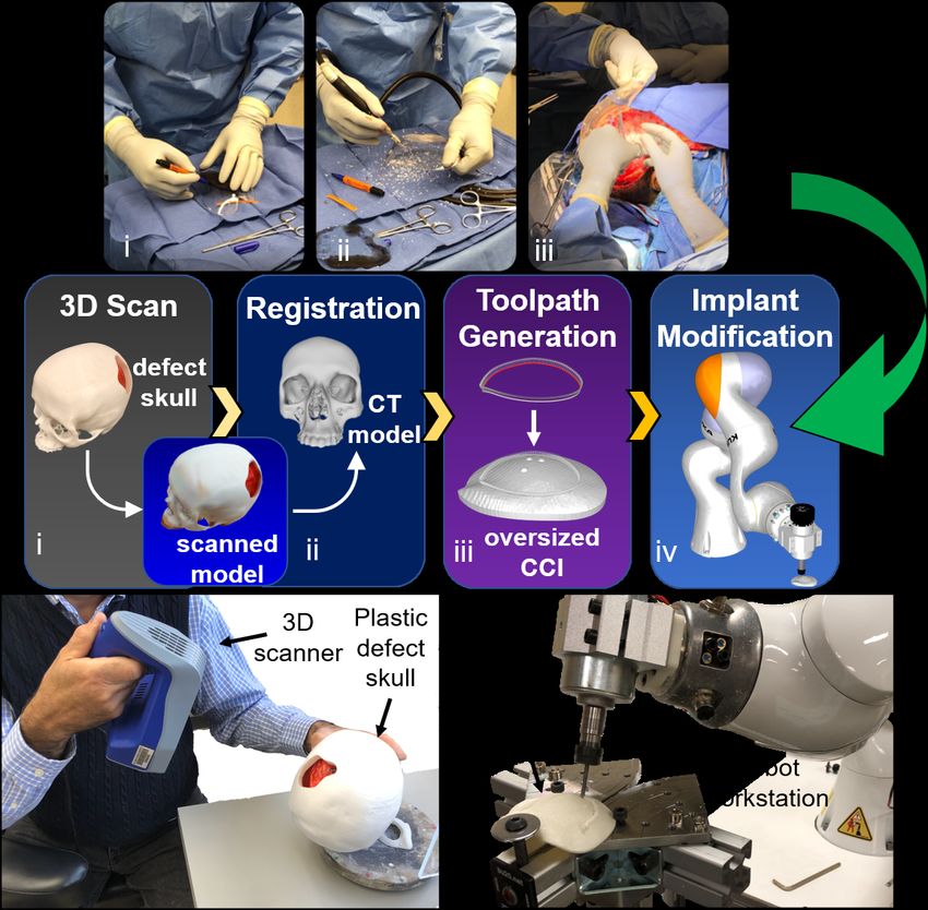
modification and 42% compared to the optical tracking method. Fig. 1. Top: A clinical example of the single-stage cranioplasty with a
prefabricated oversized CCI: i) the surgeon marks the defect contour on
the CCI. ii) the implant is manually modified by a surgical cutter. iii) the
resized CCI is fit to the skull defect. Middle: The workflow of robotic single-
I. I NTRODUCTION stage cranioplasty: i) 3D scanning generates a scanned model of the defect
Cranioplasty is a procedure to treat cranial defects due skull. ii) the scanned model is registered to the preoperative CT model.
iii) a cutting toolpath is generated. iv) a cutting robot modifies the implant.
to trauma, injury, or neurosurgical procedures for brain tu- Bottom: Left: The plastic defect skull is scanned by a handheld 3D scanner.
mors, aneurysms, or epilepsy [1]. Conventional cranioplasty Right: robot resizes the oversized implant.
is a two-stage process that repairs skull deformities in a
delayed operation [2]. Such process requires the skull to be
partially removed from the patient, who then has to wait directly into the defect of the skull or a molding template
for the design and fabrication of the replacing implant for generated using the autologous bones. However, molding
three to four weeks. In contrast, single-stage cranioplasty a CCI directly on the defect may release an exothermic
aims to restore aesthetic appearance immediately following reaction damaging nearby tissue [5]. Moreover, autologous
craniectomy within one single operation, therefore, decreas- bones cannot always be used to create a negative imprint
ing operative times and speeding up the patient’s recovery and are limited in their ability to eliminate the discontinuities
[3]. between the boundaries. Another commonly used approach is
Several approaches are utilized to generate CCIs. The a cutting guide, in which a customized implant and a cutting
molding technique has been applied to form CCIs in the guide are prefabricated, and the surgeon resects the patient’s
operating room [4]. This method requires injecting liquid skull following the cutting guide so that the skull defect
bio-compatible materials such as poly-methyl-methacrylate can be immediately closed with the prefabricated implant [6,
1 Shuya Liu is with the Department of Mechanical Engineering, Johns 7]. In addition, some other groups considered using optical
Hopkins University, Baltimore, MD. jsliu@jhu.edu navigation systems to achieve planned resections. Although
2 Weilun Huang is with the Department of Computer Science, Johns
these methods are capable of repairing skull deformities
Hopkins University, Baltimore, MD. wl.huang@jhu.edu
3 Chad Gordon is with the Department of Plastic and Recon- within one operation, they do not consider the possibilities
structive Surgery, Johns Hopkins School of Medicine, Baltimore, MD. for intraoperative plan changes, limiting neurosurgeons’ flex-
cgordon@jhmi.edu ibility in reaching specific regions of the brain [8, 9].
4 Mehran Armand is with the Department of Orthopaedic Surgery,
Mechanical Engineering, and Computer Science, Johns Hopkins University, In practice, cranioplasty replaces the skull defect with an
Baltimore, MD. marmand2@jhu.edu alloplastic implant instead of using a patient’s autologous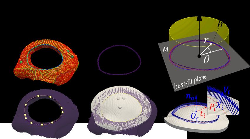
skull-bone [10]. Although additive manufacturing has been
widely used to fabricate CCIs [11]–[13], it is not realistic to
bring 3D printers into the operating room to intraoperatively
print CCIs due to its long material building process and
sterilization requirement. Therefore, the subtractive approach
with prefabricated and pre-sterilized oversized CCIs is more
practical and cost-effective. In [3, 14], a clinical approach us-
ing prefabricated oversized CCIs in single-stage cranioplasty
is presented. This approach requires a surgeon to intraoper-
atively modify an oversized CCI by manually resizing it,
which is often poor in accuracy and time-consuming.
   Computer-assisted single-stage cranioplasty provides a
method to help surgeons better visualize the defect contour
by directly projecting the defect contour on an oversized           Fig. 2. Coordinate transformations between different models. Left: patient-
                                                                    to-CT registration aligns the 3d-scanned defect mesh model (red) Fscan to
CCI. This method utilizes an optical tracking system to             the CT model (white) FCT . Right: the robot locates a prefabricated oversized
collect data points of the defect contour [15]. However,            CCI (blue) by finding the reference frame Fre f defined by three spherical
this system is difficult to set up and requires line-of-sight.      markers that originally defined in FCT . FBase is the robot’s base frame. Fee
                                                                    is the robot’s end-effector frame. FTCP is the calibrated TCP frame. The
Moreover, the planar projection from a fixed configuration          transformation between different coordinate frames are shown as T .
may not be suitable for implants with complex structures.
To address the above-mentioned problems, we previously
developed a portable projection mapping device that tracks                                        II. M ETHOD
surgical instruments and projects a 3D defect contour onto
                                                                       We developed a robotic system for resizing oversized
the implant in real-time from any angle without information
                                                                    CCIs during intraoperative operation. The system consists
loss [16]. Although this approach improves the accuracy of
                                                                    of a handheld Artec Space Spider 3D scanner (up to 0.1
projection mapping for medical augmented reality, it can
                                                                    mm resolution) and a KUKA LBR iiwa 7 R800 robotic
only collect one data point per frame with a digitizing
                                                                    arm (repeatability ±0.1mm). The 3D scanner was utilized
instrument. Therefore, this approach takes longer to collect
                                                                    to acquire 3D information of the skull defect and to export a
sufficient data points for registration.
                                                                    refined mesh (Fig. 1, bottom, left). We modified the KUKA
   Recent advances in 3D scanning technologies provide new          robotic arm into a cutting workstation by attaching a spindle
venues for extending the application of medical robots in the       tool to the robot’s end-effector (Fig. 1, bottom right).
operating room [17]. 3D scanning generates high-precision              Our intraoperative CCI modification method includes four
3D models of real-world objects that can be recognized              steps (Fig. 1, middle): 1) The information of a defected
within a robot’s workspace to achieve specific autonomous           skull is collected using a 3D scanner. 2) The scanned data
tasks. Different from the optical tracking system, a 3D             is registered to the CT model space. 3) A cutting toolpath
scanner can collect thousands of data points per frame              is generated by extracting the defect contour. 4) A cutting
without contacting the object. The use of a 3D scanner for          robot resizes the CCI according to the generated toolpath.
skull defect reconstruction can simplify and expedite the
identification of the defect’s contour.                             A. 3D reconstruction of a patient’s defect skull
                                                                       A 3D scanning process was first utilized to acquire intra-
  In this paper, we present a novel system for generating
                                                                    operative patient data. During this process, the 3D scanner
precise CCIs for patients in single-stage cranioplasty. The
                                                                    was held by hand at an approximate half meter away from
system consists of a 3D scanner and a cutting robotic arm.
                                                                    the skull and moved slowly around it. This process could be
The 3D scanning technique enables fast registration and
                                                                    terminated when there were sufficient 3D data shown in the
generation of cutting toolpaths. The cutting robotic arm
                                                                    visualization software (Artec Studio). This process usually
provides stable and accurate performance compared to the
                                                                    takes less than two minutes.
conventional manual cutting approach by surgeons and an
existing method using an optical tracking system.                   B. Patient-CT registration
  The contributions of this work include:                              The 3D-scanned data was then registered to the preopera-
                                                                    tive CT model of the patient’s skull. This process transformed
  •   We proposed a fast and non-contact approach for ac-           the scanned data to the CT model space, as shown in Fig.
      quiring defect contour information using a handheld 3D        2. An iterative closest points (ICP) registration method [18]
      scanner.                                                      was applied to refine the registration. Three anatomical points
  •   We developed an algorithm for generating cutting tool-        were artificially designed on the defect skull and were picked
      paths by extracting defect contours.                          from the 3d-scanned model for ICP initialization.
  •   We integrated a robotic system for automated implant             Since the preoperative CT model has two layers separated
      modification.                                                 by the bone thickness, during the registration process, the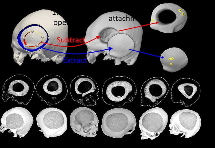
Fig. 3. Toolpath generation. (i) A curvature filter followed by manual
cleaning is applied to the 3d-scanned defect data to extract the vertices of the
defect contour. (ii) The remaining vertices are fitted to a plane, transformed     Fig. 4. Implant and skull defect generation. Top: the skull defect (a)
to a local cylindrical coordinate system defined on the plane parameterized        and the implant (b) are generated by (1) a boolean operation between the
as (θ , r, h), and then fitted to a polynomial curve. (iii) The fitted curve is    skull and two customized contours (red contour: skull defect, blue contour:
converted into a spline curve interpolated through control points. (iv) The        implant) and (2) attaching spherical markers to their surfaces. The skull
control points are projected onto the registered implant’s top surface. (v) A      defect is cropped to a 3-D printable size. Bottom: the skull defects (top)
cutting toolpath is generated from the spline curve.                               and implants (bottom) for six different specimens are generated.

3d-scanned data tends to mistakenly overlap with the inner                         the maximum and minimum values of the principal curvature
layer of the skull, because of the similar geometric feature                       on the mesh [20]. This filter was able to identify crease
between the inner and outer layer. To prevent this problem,                        changes by the curvature of the surface mesh. After curvature
we designed a preprocessing algorithm to convert the closed                        filtering, only the vertices near the dropping edges were kept
CT model to an open surface mesh by removing the inner                             (Fig. 3, i). Additional manual cleaning was performed to
layer.                                                                             further remove potential redundant vertices that were far off
    In this method, we defined the 3D position of each vertex                      the edge.
in the CT skull mesh as qi ∈ R3 . The   center of the mesh o ∈                         2) Curve Fitting: After removing all the redundant ver-
                                   ∑n qi
R3 can be approximated by: o = i=1   n . Then we constructed
                                                                                   tices, a group of vertices around the defect edge were
vector vi , which points from the center o to each vertex                          remained denoted as M (Fig. 3, ii). We defined a local
qi . Since each vertex in the skull mesh is also associated                        cylindrical coordinate system on a best-fit plane of the
with a normal vector ni of its own. The vectors of the inner                       extracted contour parameterized as (θ , r, h). The center of
layer point to the hollowed space inside the skull towards                         the cylindrical coordinate system was obtained by the mean
the center o, while the vectors of the outer layer point to the                    coordinates of the remaining vertices. A nonlinear least-
opposite directions. As a result, the sign of qi · ni determines                   squares method was then used to fit a closed polynomial
whether this vertex is located in the inner layer or the outer                     curve to these vertices expressed in the cylindrical coordi-
layer. Vertices with negative dot products were removed to                         nates.
keep only the outer layer of the CT mesh model.                                        3) Spline Projection: The fitted curve was then converted
                                                                                   into a spline curve, which consists of several control points
C. Toolpath Generation                                                             along the curve. Although the 3d-scanned defect was reg-
   To generate a toolpath for the subsequent resizing process,                     istered to the CT model after patient-to-CT registration,
the defect contour was first extracted from the 3d-scanned                         the extracted defect contour may not perfectly align to the
mesh of the skull defect. Then, the 3d-scanned defect was                          implant’s top surface due to registration error. To eliminate
registered to the preoperative CT model. Therefore, the                            the error, the control points were projected onto the top
implant was aligned to the 3d-scanned defect model in the                          surface of the implant mesh so that the spline curve would
CT coordinates. A toolpath consisting of cutting positions                         adjust its shape to match the curvature of the implant’s top
and vectors along the extracted contour was generated in                           surface (Fig. 3, iv).
the implant coordinate system, as shown in Fig. 3. We                                  4) Toolpath Generation: For each discretized point Pi of
implemented the following steps to generate 3D cutting                             the spline curve, a unit 3D vector Vi was added to define
toolpaths with visualization using Pyvista [19]:                                   the tool center point (TCP)’s axis orientation. Each Vi was
   1) Curvature Filter: To extract the contour of the defect,                      computed by tilting a constant angle from no , the normal
a curvature filter was applied to the vertices of the 3d-                          vector of the best-fit plane, toward ti , a vector defined from
scanned mesh and followed by manual cleaning. We utilized                          the center point Oc to each curve point Pi . A cutting toolpath
a curvature filter to determine the local mean curvature along                     was then obtained by combining each curve point Pi with its
the surface of the defect and extracted the high curvature                         associated cutting vector Vi . To compensate the tool radius,
value above a designed threshold. The mean curvature H                             the curve points ∑ Pi were expanded to ∑ Xi by an offset
was calculated as H = 12 (κ1 + κ2 ) , where κ1 and κ2 are                          equal to the radius of the cutting bit (Fig. 3, v).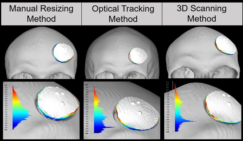
III. E XPERIMENTAL S ETUP
   To evaluate the implant-resizing accuracy of our integrated
system, we compared our method with the surgeon’s manual-
resizing method and an existing optical tracking method.
We conducted six experiments with independently generated
skull defects with different sizes and shapes. The defect
specimens were generated using boolean operations. As
shown in Fig. 4 (Top), we first subtracted the mesh inside the
red contour from a complete skull to create a defect on the
skull. On the same complete skull, the implant mesh inside
the blue region was extracted to create its corresponding
oversized implant. The defected skull was further cropped
by a plane to a 3D printable size and was fabricated using
a 3D printer (Stratasys F370, ABS material). Finally, we
created three spherical markers on the top surface of each
cropped defect and its corresponding implant for Patient-CT
registration and implant localization.

A. Method Comparison
   We compared the implants generated by our method with
the manual resizing method, as well as the optical tracking        Fig. 5. Top: a) collecting the defect contour by optical tracking system.
                                                                   b) scanning the defect contour with a handheld 3D scanner. c) robot TCP
method used by Murphy et al. [15]. For robotic cutting, the        calibration errors
cut depth was set to 3 mm, which is the thickness of the
3d-printed implants. The cut angle was set to 20 degrees
for all the generated cutting toolpaths to generate beveled        the reference markers defined in Fre f could be transformed
boundaries.                                                        to robot’s frame FBase . The registration between the robot
   1) Manual resizing method: We provided the surgeon              space and CT space was then achieved based on the known
with pre-designed partial skulls with the generated defects        locations of the markers, described in the FBase and in the
and corresponding oversized implants. The surgeon first            FCT respectively.
outlined the defect contour of each specimen manually on
the implant based on his visual judgment. He then resized the      D. Hardware Details
implant with a hand-held cutting tool following the outline.          The integrated system was set up on a computer running
   2) Optical tracking method: The optical tracking method         Intel Core i7-6820HQ @ 2.7GHz CPU. The 3D scanner
used a digitizing instrument and an optical tracking system        (Artec Spider) collects data at 15 HZ. The KUKKA robot is
to trace the defect contour (Fig. 5, a). Instead of manual         operated using online mode via RoboDK 1 . The registration
resizing, the oversized implants were then resized by the          between the 3D-scanned model and the CT model was
same cutting robot and with the same cutting parameters            implemented in Meshlab [22], open-source software for mesh
described above.                                                   processing. The NDI Polaris optical tracking system operates
                                                                   at 10 Hz (± 0.3 mm tracking accuracy) was used in the
B. Tool Center Point (TCP) Calibration                             comparison experiment.
   The transformation between the tip of the spindle tool
                                                                                               IV. R ESULT
and the robot arm’s end-effector was calibrated using a pivot
calibration [21]. In this method, we hand-guided the robotic       A. Registration
arm to different poses, such that the TCP always touches              1. Optical Tracking Method
the tip of a fixed pin. The accuracy of the TCP calibration,       Three anatomical markers were artificially added to the
measured by the TCP error, is shown in Fig. 5, and the             original CT models and were 3D printed with the defect
relative pose from Fbase to FTCP :                                 specimens. The anatomical points on the printed specimens
                 Base            Base           ee                 were localized in the optical tracking system with a tracking
                        TTCP =          Tee ·        TTCP
                                                                   instrument (Fig. 5a). Each defect specimen was registered
C. Implant Localization                                            back to the CT coordinate system using point set registration
                                                                   based on singular value decomposition [23]. The registration
   The oversized CCI was secured on the robot’s working
                                                                   error was given by the mean Cartesian distance between
platform with bolts during the resizing process (Fig. 1,
                                                                   the registered anatomical points and the original anatomical
bottom, right). In order to obtain the relative position and
                                                                   points defined in the CT space (Table I).
orientation of the oversized CCI in the robot space (Fig. 2,
right), we hand-guided the robot’s spindle TCP to touch the           1 RoboDK is an offline programming and simulation software for indus-
tip of each spherical marker separately so that the locations of   trial robots. https://robodk.com/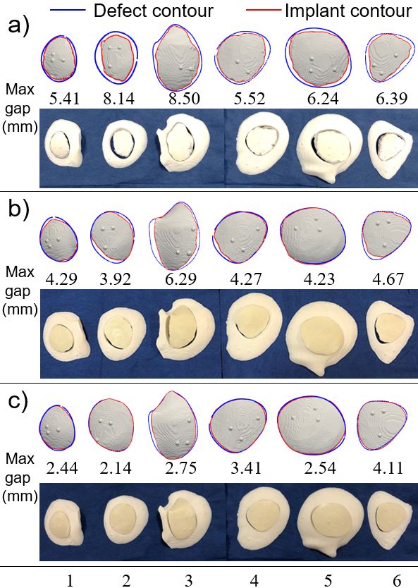
Fig. 6. An example of gap distance analysis (specimen 1). Left, mid-
dle, right show the results of the conventional manual modification, the
existing optical tracking method, and our proposed 3D scanning method,
respectively. Top and bottom show their overviews and zoomed views. The
color bars in the bottom plots show the gap distance between the implant’s
boundary and the defect edge.

   2. 3D Scanning Method
After 3D scanning the defect specimen, we first manually
aligned the three anatomical points on the defect with the
original anatomical points defined in the CT model as an
initialization. Then ICP was used to fine-tune the registration
of the scanned specimen to the original CT model. The error
was evaluated by calculating the mean distance between all
of the valid vertices and their closest vertices in the original
CT model (Table I).
                                TABLE I                                      Fig. 7. Cutting performance. Visualization of the defect contour (blue
                                                                             curve) and implant contour (red curve) for a) conventional manual modifi-
              R EGISTRATION E RRORS OF T WO M ETHODS                         cation, b) optical tracking method, and c) 3D scanning method. The numbers
                                                                             in the middle of each plot show the maximum gap distance.
      Specimen            1       2        3       4       5        6
  Optical Tracking
     Point Cloud        0.39     0.38    0.32    0.32     0.30    0.34
  registration (mm)                                                          since the surgeon would repeatedly trim the implant until it
    3D Scanning                                                              fits into the defect. Yet, for optical tracking and 3D scanning
                        0.04     0.02    0.04    0.04     0.05    0.03
      ICP (mm)
                                                                             methods, the post-completed implant could be slightly larger
                                                                             than the defect boundaries, which would not completely fit
                                                                             into the defect.
B. Evaluation of resized implants
                                                                                Among the six defect specimens, the third specimen was
   The post-completed implants were physically fitted to the                 considered the most difficult case due to the complex shape
defect specimens. First, we scanned the implants sitting on                  above the eye orbit. Although the gap analysis for our pro-
their respective defects with a 3D scanner and registered                    posed approach showed the fourth and the sixth specimens
to their original CT models using the artificial anatomical                  had larger maximum bone gaps than the third specimen,
points on the defect specimens. We then 3d-scanned the                       this corresponds to the fact that the resized implants did
post-completed implants individually and registered to the                   not completely fit into the defect and would require slight
previous 3D scans using the three artificial fiducial points                 trimming. Among the mentioned three methods, Fig. 8
created on each implant so that each post-completed implant                  shows that our proposed 3D scanning method with robotic
model could be positioned correctly relative to the ground                   integration was the only one with the mean gap distance
truth defect model.                                                          below 1.5 mm.
   We then evaluated the gap distances between the bound-
aries of the post-completed implants and their corresponding
                                                                             C. Time cost
defect edges. The gap distances were visualized in Meshlab
[22] (Fig. 6). We used the gap distance distribution (maxi-                    The resizing process by our proposed method took about
mum, mean, and standard deviation) to quantify the error for                 10-15 minutes, including the setup time, which was similar
each method for the 6 specimens. Fig. 7 shows the analysis                   to the optical tracking method, whereas the conventional
of the max gap distance. For the manual resizing method,                     manual approach takes a range from ten to eighty minutes
all the resized implants were smaller than the defect edges                  by expert surgeons.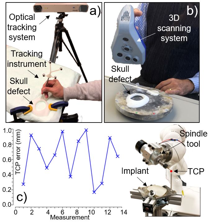
the optimal cutting parameters for smooth cutting of the
                                                                          implant. 3) In the clinical setting, due to the minimally
                                                                          exposed surgical area (Figure 1, Top, iii), the process of
                                                                          registering a patient’s defect scan to the CT model may be
                                                                          challenging. A possible remedy is to use two separate 3D
                                                                          scans at different times during the procedure. Prior to the
                                                                          draping of the patient, fiducial marks will be attached to the
                                                                          patient. The first scan will acquire the full exposed head with
                                                                          fiducial marks attached and register this head model to the
                                                                          preoperative CT scan of the patient’s skull. After draping
                                                                          the surgical area and subsequent skull resection, a second
                                                                          scan containing the defect area information will be registered
                                                                          to the first scan using the information obtained from the
                                                                          fiducial marks. Thereby, the defect scan can be mapped to
Fig. 8. Cutting accuracy evaluation. Mean and standard deviation of the
gap distance between the implant and the defect of conventional manual    the CT model through the intermediate scan obtained prior
modification (blue), optical tracking method (orange), and 3D scanning    to draping.
method (green) for six specimens.

                                                                                                       R EFERENCES
                         V. D ISCUSSION                                    [1] S. Aydin, B. Kucukyuruk, B. Abuzayed, S. Aydin, and G. Z. Sanus,
                                                                               “Cranioplasty: review of materials and techniques,” Journal of neuro-
   We present a novel method for intraoperatively fabricating                  sciences in rural practice, vol. 2, no. 2, p. 162, 2011.
precise CCI in single-stage cranioplasty. In the proposed                  [2] C. M. Pasick, K. Margetis, G. F. Santiago, C. Gordon, and P. J. Taub,
method, we first scan the defect to create a mesh model. The                   “Adult cranioplasty,” Journal of Craniofacial Surgery, vol. 30, no. 7,
                                                                               pp. 2138–2143, 2019.
mesh model is then registered to the reconstructed 3D model
                                                                           [3] J. U. Berli, L. Thomaier, S. Zhong, J. Huang, A. Quinones, M. Lim,
from the preoperative CT in order to define the contour of the                 J. Weingart, H. Brem, and C. R. Gordon, “Immediate single-stage
defect. Next, a cutting toolpath is generated using a discrete                 cranioplasty following calvarial resection for benign and malignant
spline curve to represent the defect contour. After localizing                 skull neoplasms using customized craniofacial implants,” Journal of
                                                                               Craniofacial Surgery, vol. 26, no. 5, pp. 1456–1462, 2015.
the oversized CCI with respect to the robot’s base frame, the              [4] A.-R. Fathi, S. Marbacher, and A. Lukes, “Cost-effective patient-
cutting robot automatically resizes the implant to generate                    specific intraoperative molded cranioplasty,” Journal of craniofacial
the final shape to fit the defect.                                             surgery, vol. 19, no. 3, pp. 777–781, 2008.
                                                                           [5] S. Marbacher, L. Andereggen, S. Erhardt, A.-R. Fathi, J. Fandino,
   The proposed method improves the accuracy of the cut by                     A. Raabe, and J. Beck, “Intraoperative template-molded bone flap
56% compared to the surgeon’s cut and 42% compared to the                      reconstruction for patient-specific cranioplasty,” Neurosurgical review,
optical tracking method. Moreover, the implant cut bound-                      vol. 35, no. 4, pp. 527–535, 2012.
                                                                           [6] H. Eufinger, A. R. Wittkampf, M. Wehmöller, and F. W. Zonneveld,
aries as created by the robot were considerably smoother than                  “Single-step fronto-orbital resection and reconstruction with individual
those created by the expert surgeon. The smooth boundary                       resection template and corresponding titanium implant: a new method
may contribute to the better fit of implants to the defect area                of computer-aided surgery,” Journal of Cranio-Maxillofacial Surgery,
                                                                               vol. 26, no. 6, pp. 373–378, 1998.
in actual surgical scenarios. Our proposed method signifi-                 [7] G. Gerbino, F. A. Bianchi, E. Zavattero, F. Tartara, D. Garbossa, and
cantly reduced the operation time compared to the expert                       A. Ducati, “Single-step resection and reconstruction using patient-
surgeon’s performance time of 10-80 minutes, as reported                       specific implants in the treatment of benign cranio-orbital tumors,”
                                                                               Journal of Oral and Maxillofacial Surgery, vol. 71, no. 11, pp. 1969–
by Berli et al [3]. The robotic modification of oversized                      1982, 2013.
CCIs was shown to be more consistent and accurate when                     [8] F. Jalbert, S. Boetto, F. Nadon, F. Lauwers, E. Schmidt, and R. Lopez,
compared to the expert surgeon’s performance. Of note, we                      “One-step primary reconstruction for complex craniofacial resection
                                                                               with peek custom-made implants,” Journal of Cranio-Maxillofacial
used an available seven DOF Kuka robot to perform the                          Surgery, vol. 42, no. 2, pp. 141–148, 2014.
cutting tasks. However, a cheaper six DOF robot or a five-                 [9] P. Dodier, F. Winter, T. Auzinger, G. Mistelbauer, J. M. Frischer,
axis laser cutting machine (e.g. [24]) can also successfully                   W.-T. Wang, A. Mallouhi, W. Marik, S. Wolfsberger, L. Reissig
                                                                               et al., “Single-stage bone resection and cranioplastic reconstruction:
perform smooth cutting as proposed for this research.                          comparison of a novel software-derived peek workflow with the
   Some of the limitations of the current study are as follows:                standard reconstructive method,” International journal of oral and
1) During the toolpath generation process, the cut angle                       maxillofacial surgery, vol. 49, no. 8, pp. 1007–1015, 2020.
defining the tool axis attached to the discretized points along           [10] A. M. Shah, H. Jung, and S. Skirboll, “Materials used in cranioplasty:
                                                                               a history and analysis,” Neurosurgical focus, vol. 36, no. 4, p. E19,
the defect contour was constant. In actual surgical scenarios,                 2014.
This may cause problems in fitting the implant if the defect              [11] B.-J. Kim, K.-S. Hong, K.-J. Park, D.-H. Park, Y.-G. Chung, and S.-
boundary is not beveled uniformly. The extension of this                       H. Kang, “Customized cranioplasty implants using three-dimensional
                                                                               printers and polymethyl-methacrylate casting,” Journal of Korean
work will include the development of an algorithm that can                     Neurosurgical Society, vol. 52, no. 6, p. 541, 2012.
extract the bevel angle of the defect wall from the scan                  [12] E.-K. Park, J.-Y. Lim, I.-S. Yun, J.-S. Kim, S.-H. Woo, D.-S. Kim, and
data. 2) In this study, the manually-tuned, experimentally-                    K.-W. Shim, “Cranioplasty enhanced by three-dimensional printing:
                                                                               custom-made three-dimensional-printed titanium implants for skull
determined cutting speed and spinning rate of the tool were                    defects,” Journal of Craniofacial Surgery, vol. 27, no. 4, pp. 943–
not optimized. Additional experiments are needed to evaluate                   949, 2016.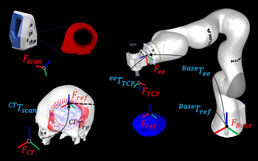
[13] J. A. Morales-Gómez, E. Garcia-Estrada, J. E. Leos-Bortoni,
     M. Delgado-Brito, L. E. Flores-Huerta, A. Adriana, L. J. Torres-Dı́az,
     and Á. R. M.-P. de León, “Cranioplasty with a low-cost customized
     polymethylmethacrylate implant using a desktop 3d printer,” Journal
     of neurosurgery, vol. 130, no. 5, pp. 1721–1727, 2018.
[14] A. Wolff, G. F. Santiago, M. Belzberg, C. Huggins, M. Lim, J. Wein-
     gart, W. Anderson, A. Coon, J. Huang, H. Brem et al., “Adult cran-
     ioplasty reconstruction with customized cranial implants: preferred
     technique, timing, and biomaterials,” Journal of Craniofacial Surgery,
     vol. 29, no. 4, pp. 887–894, 2018.
[15] R. J. Murphy, K. C. Wolfe, P. C. Liacouras, G. T. Grant, C. R. Gordon,
     and M. Armand, “Computer-assisted single-stage cranioplasty,” in
     2015 37th Annual International Conference of the IEEE Engineering
     in Medicine and Biology Society (EMBC). IEEE, 2015, pp. 4910–
     4913.
[16] S. Liu, W.-L. Huang, A. Shin, C. Gordon, and M. Armand, “A portable
     projection mapping device for medical augmented reality in single-
     stage cranioplasty,” in Optical Architectures for Displays and Sensing
     in Augmented, Virtual, and Mixed Reality (AR, VR, MR), vol. 11310.
     International Society for Optics and Photonics, 2020, p. 1131007.
[17] A. Haleem and M. Javaid, “3d scanning applications in medical field:
     a literature-based review,” Clinical Epidemiology and Global Health,
     vol. 7, no. 2, pp. 199–210, 2019.
[18] P. J. Besl and N. D. McKay, “Method for registration of 3-d shapes,”
     in Sensor fusion IV: control paradigms and data structures, vol. 1611.
     International Society for Optics and Photonics, 1992, pp. 586–606.
[19] C. B. Sullivan and A. A. Kaszynski, “Pyvista: 3d plotting and mesh
     analysis through a streamlined interface for the visualization toolkit
     (vtk),” Journal of Open Source Software, vol. 4, no. 37, p. 1450, 2019.
[20] M. Meyer, M. Desbrun, P. Schröder, and A. H. Barr, “Discrete
     differential-geometry operators for triangulated 2-manifolds,” in Vi-
     sualization and mathematics III. Springer, 2003, pp. 35–57.
[21] W. Birkfellner, F. Watzinger, F. Wanschitz, R. Ewers, and
     H. Bergmann, “Calibration of tracking systems in a surgical envi-
     ronment,” IEEE transactions on medical imaging, vol. 17, no. 5, pp.
     737–742, 1998.
[22] P. Cignoni, M. Callieri, M. Corsini, M. Dellepiane, F. Ganovelli, and
     G. Ranzuglia, “Meshlab: an open-source mesh processing tool.” in
     Eurographics Italian chapter conference, vol. 2008. Salerno, 2008,
     pp. 129–136.
[23] K. S. Arun, T. S. Huang, and S. D. Blostein, “Least-squares fitting
     of two 3-d point sets,” IEEE Transactions on pattern analysis and
     machine intelligence, no. 5, pp. 698–700, 1987.
[24] J. Liu, J. Fang, R. J. Murphy, C. Gordon, and M. Armand, “Design
     and development of 5-axis cranial implant laser cutting system,” in In-
     ternational Design Engineering Technical Conferences and Computers
     and Information in Engineering Conference, vol. 58110. American
     Society of Mechanical Engineers, 2017, p. V001T02A051.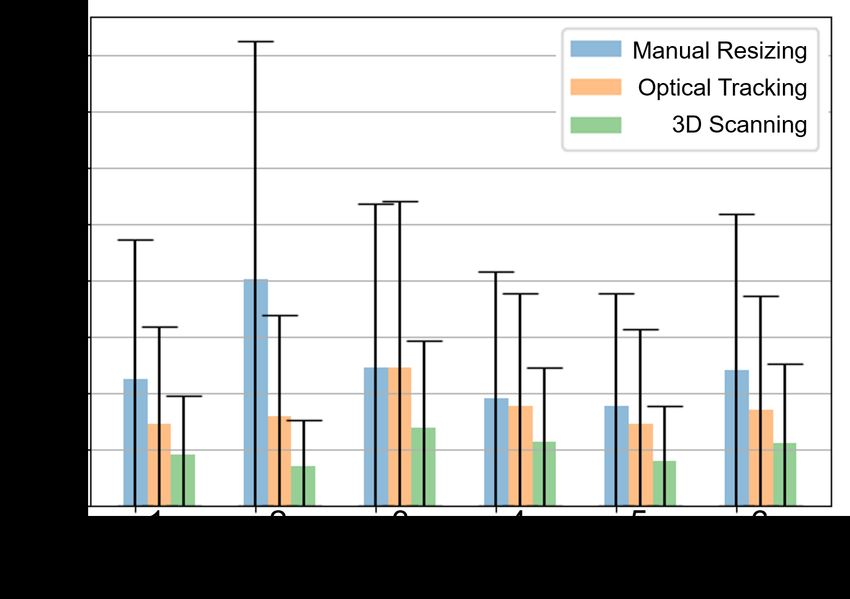
You can also read