A Short History of Telecommuni-cations Transmission in the UK
←
→
Page content transcription
If your browser does not render page correctly, please read the page content below
Keith Ward

           A Short History of Telecommuni-
           cations Transmission in the UK

                        There is no doubt that when considering the evolution              illustrated in Figure 11 and if it were possible
                                                                                           to show today’s high-capacity dense
                        of the telecommunications network, the development
                                                                                           wavelength division multiplexing (DWDM)
                        of switching tends to grab the headlines because it is             it would be a fraction of a percent on the
                        the platform that supports the majority of services.               graph.

                        But it could be argued that the transmission bearer
                        network has had an equally dramatic impact because                 In the Beginning – the Audio
                        of the many developments and their influence on the                Era
                        network cost and capacity. It is also the continuing
                        bedrock of all telecommunications                                  The first example of long-distance telephony
                                                                                           in the UK was the demonstration by
                                                                                           Alexander Graham Bell of his telephone
                                           Introduction                                    (invented in 1876) to Queen Victoria in
                                                                                           January 1878, which required a single wire
the development of                         In 1956, the 50th anniversary of the IPOEE, I   earth return circuit from London to
                                           was a technical officer working in              Southampton. Prior to this there was a large
transmission systems has                   Canterbury repeater station and had given,      network of telegraph circuits stemming from
                                           with a colleague (John Luetchford), my first    the introduction of the electrical telegraph in
been driven by the need to                 IPOEE presentation to the Canterbury Area       the UK in 1838 by Cook and Professor
                                           local section on my experiences as a            Wheatstone of Kings College, initially used
reduce unit costs in the                   National Service RAF radar mechanic,            for railway communications in the UK –
                                           which introduced me to digital circuits and     sometimes known as the Victorian Internet.
                                           microwave radio. At that time the, then,        Growth was rapid and by 1890 there were
face of an exponential                     GPO was converting 12-channel carrier           over 12 000 telegraph offices1. But the
                                           systems to 24-channel working and most of       performance requirements for (digital)
growth in capacity                         the circuits were 4-wire audio with valve       telegraphy were far less stringent than for
                                           amplifiers (Amps 32), known as repeaters.       the range of voice frequencies of analogue
requirements                               The switched network was being                  telephony. The early telephone lines were
                                           modernised by the replacement of manual         overhead on poles or attached to rooftops.
                                           exchanges with electromechanical Strowger       They were single line with an earth return,
                                           exchanges. Towards the end of my BT             made of iron or steel and were inherently
                                           career, in the 1980s, as Chief Engineer         noisy. The benefits of using copper were
                                           responsible for UK network planning and         understood but copper wires could not be
                                           works, my responsibilities included the         made strong enough for overhead lines. But
                                           transmission network which had progressed       in 1877, Thomas Dolittle of Connecticut
                                           from copper pairs and the early coaxial         developed the process of hard drawn
                                           cable systems, to software-controlled           copper, which took over the line market.
                                           synchronous digital hierarchy (SDH)             Although public telephony in the UK
                                           155 Mbit/s systems and the early forms of       commenced with local systems (the first at
                                           wavelength division multiplexing (WDM). I       London’s Coleman Street in 1879), in 1884
                                           have therefore been privileged to be            new licences were granted which removed
                                           involved in many of the most exciting devel-    geographical restrictions leading to the
                                           opments in telecommunications history.          growth of inter-town links, e.g. Manchester
                                                In the early days of telecommuni-          to Liverpool and Glasgow to Edinburgh. The
                                           cations, the cost of interconnecting            Telegraph Act of 1892 nationalised the
                                           telephone exchanges with the transmission       provision of the long-distance trunk
                                           network was a major consideration and the       network under the General Post Office who
The Author: Professor Keith Ward is with   development of transmission systems has         planned a more comprehensive coverage of
University College London.                 been driven by the need to reduce unit costs    the UK based on 800 lb/mile overhead
                                           in the face of an exponential growth in         copper wires for main routes such as
                                           capacity requirements. The success is           London to Glasgow, i.e. 320 tons per 2-wire

30                                                            The Journal of The Communications Network   • Volume 5 Part 1 • January–March 2006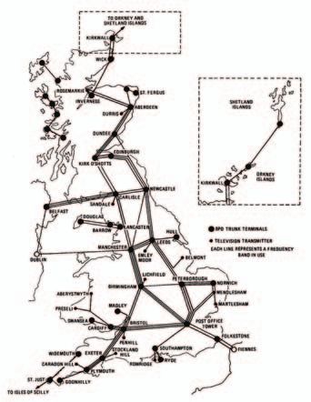
A Short History of Telecommunications Transmission in the UK

Figure 1 Relative capital cost of providing a 100-mile trunk circuit

    100                                                                                    200                                    by the introduction of cable balancing. This
                       300 lb/mile                                                                                                was a systematic jointing process that
                       Overhead Copper Wire                                                                                       minimised the length that two circuits were
                                                                                                                                  adjacent in a cable.
                                                             Cost at 1963 Prices
           80                                                                              160                                          The major breakthrough in the fight to
                                                                                                                                  reduce the cost of transmission came with
                                                             Historical Cost                                                      the invention in 1904, by Professor Sir John
                                                                                                                                  Ambrose Fleming of UCL, of the thermionic

                                                                                                 Trunk Circuits, thousands
                                                                                                                                  valve4 and the introduction, by Lee de
           60                                                                              120                                    Forest, of the grid to enable the design of the
 Cost, %

                        70 lb Copper
                        Conductor in                                                                                              valve amplifier. This led to the use of light
                            Cable                                              Capacity                                           gauge loaded conductors with valve
                         Repeatered  20 lb Copper                                                                                 amplifiers, known as repeaters, the first of
           40                        Conductor in                                          80                                     which was introduced in the UK
                                     Cable 4-wire                                                                                 immediately after the great storm of 27
                                   Repeatered Circuit                                                                             March 1916, which severed all overhead
                                              12 Channel                                                                          lines between London and the North. This
           20                                   Carrier                                    40                                     left the only communication via the London
                                                                                                                                  – Birmingham – Liverpool cable that had
                                                         600 Channel                                                              been installed a fortnight before. It was
                                                         Coaxial Cable    2700 Channel
                                                                          Coaxial Cable                                           important to restore communications to
                                                                                                                                  Ireland and two repeaters were installed at
                1913       1923        1933     1943         1953        1963                                                     Liverpool on the extensions to Dublin and
                                                                                                                                  Belfast. By 1922 there were 2-wire and 4-
                                                                                                                                  wire types of repeater, which were installed
circuit, 600 lb for secondary routes, e.g.              However, the performance of loading on                                    in buildings that became known, to this day,
Cardiff – Birmingham, and 400 lb for shorter            open-wire circuits was difficult to achieve.                              as repeater stations, the number of which
routes such as London – Brighton2. To                   By 1916, the UK had the longest phantom                                   increased from 18 in 1924 to 45 in 1932 (see
minimise crosstalk a transposition scheme               loaded cable, London – Liverpool, in                                      Figure 42).
was used where pairs of wires forming one               Europe, and in 1922 it had over half the                                       The backbone of the UK trunk
circuit occupied diagonally opposite corners            mileage of all loaded cable in Europe. A                                  telephone system in the 1920s consisted of
of a square of wires, which was rotated in a            great deal of development was carried out                                 the London – Birmingham and London –
systematic manner along the overhead                    on loading coils to reduce their size (see                                Glasgow cables and comprised a mix of 2-
route2. The noise problem was largely                   Figure 32) and increase their efficiency so                               wire and 4-wire amplified circuits on 20 and
overcome when Alexander Graham Bell                     that they could be positioned in cable joints                             40lb/mile cables. Eventually 20 lb conduc-
(who studied at University College London)              instead of separate containers, known as                                  tors were adopted for long-distance cables
developed and patented the 2-wire circuit.              loading pots.                                                             and, to meet the standards organisation
By 1910 serious congestion of aerial routes                  Although loading helped by reducing                                  CCIF (later known as CCITT, and now ITU-T)
was becoming a problem (see Figure 2 3),                the loss to transmitted speech, it had a low                              recommendations in 1934 for a working
particularly around London, which                       cut-off frequency and lowered the velocity                                bandwidth of 2600 Hz, 88 mH loading coils
prompted the development of underground                 of propagation and this led to lighter                                    were adopted at 2000 yd spacing. Line
cables.                                                 loadings. The problem of noise in the form                                equalisation was used to provide a
      It was not surprising that the high               of crosstalk between circuits was minimised
consumption of copper meant that its cost                                                                                          Figure 3 Loading coils from
dominated network economics in the early                Figure 2 An H-pole route                                                            1900 to 1956
days of telephony. With the rise of copper
prices, efforts to improve the efficiency of
cables increasingly occupied the thoughts of
early engineers. So-called phantom circuits
were created by connecting to the centre
points of the line transformers of two pairs
to form an additional pair, often used for
signalling over a four-wire circuit. An
important reduction in copper requirements
was made by the use of loading coils. In
1893, Oliver Heaviside made theoretical
predictions about the impact of including
inductive elements in transmission lines to
reduce attenuation and frequency distortion,
i.e. loading coils. His work was further
developed and demonstrated practically by
Michael Pupin. In the UK, loaded long-
distance cables were installed as far back as
1902 on the Liverpool – Warrington cable2.

The Journal of The Communications Network      • Volume 5 Part 1 • January–March 2006                                                                                                 31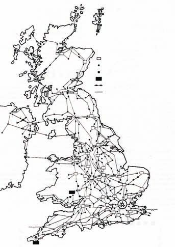
A Short History of Telecommunications Transmission in the UK

                                                                                                             in the early days of
reasonably flat frequency response over                   Meanwhile, for the junction network, i.e.
                                                                                                             telephony, transmission
trunk circuits. The last of the mass-                     circuits between local exchanges and to
produced amplifiers was the PO designed                   trunk exchanges, it was recognised that            losses were the major and
Amplifier No 32, shown in Figure 55, which                substantial capital savings could be
was a negative feedback amplifier with a                  obtained by converting existing 4-wire             expensive problem to
stable and uniform gain of 27 dB. By 1956                 amplified routes to 2-wire working,
well over 100 000 were in use. I have fond                particularly in cases where additional cables      overcome
memories of working with these amplifiers                 would be required. This required the
at Canterbury repeater station in the 1950s.              development of 2-wire amplifiers, and              of performance was required that would
A higher bandwidth, 50–6400 Hz was                        negative-impedance devices were                    allow the many routings between
required for circuits used for the distribution           particularly promising. Based on experience        subscribers to be assessed to ensure that all
of BBC broadcast programmes and picture                   in the USA, a negative-impedance repeater          were satisfactory. In 1904 the American
telegraphy (later known as facsimile) used                was developed for use in the UK network for        Telephone & Telegraph Company(AT&T)
by newspapers to transmit pictures for                    circuits no longer than 30 miles routed on         formulated a standard unit of assessment
publication. Such, so- called, music circuits             20 lb/mile PCQT cable with standard                known as the ‘mile of standard cable’
required stringent control of distortion,                 loading (88 mH coils at 2000 yd intervals6).       (msc). This was equivalent to a mile of dry-
noise and crosstalk and used special high-                                                                   core cable-pair with a loop resistance of
quality amplifiers (the Amplifier No 35).                                                                    88 ohm/mile and a mutual capacitance of
     By 1962, transistor performance,                     The Emergence of Standards                         0.054 (F/mile). An inductance of 1 mH/mile
reliability and cost were sufficient for the                                                                 and a leakance of 1 mho/mile were
standard valve-type audio line amplifier                                                                     subsequently added in the UK version. For
(Amplifier No 32) to be superseded by a                   The rapid expansion of telegraph                   measurement purposes, lines were to be
transistor version designed by the British                communications between a growing                   terminated by a standard telephone
Post Office (BPO) research department.                    number of countries prompted 20 European           instrument specification. Early tests by the
                                                          states to establish, in 1865, the International    PO and National Telephone Co led to the
 Figure 4 Existing and authorised                         Telegraph Union (ITU) to agree rules for           conclusion that commercially acceptable
          repeater stations 1925                          international interconnection and common           speech was achievable over a connection of
                                                          equipment standards. In 1871 the Society of        46 msc and by 1905 the standard stipulated
                                                          Telegraph Engineers was formed in the UK           that connections not more than 50 miles
                                                          to promote the development of electrical           apart should be no worse than 30 msc and
                                                          engineering and later became the IEE. By           20 msc if under 10 miles apart with the
                                                          the 1920s the global spread of com-                connection between the subscriber and the
                                                          munications in its many forms caused the           PO trunk system no worse than 5 msc 2. As
                                                          organisation of the ITU to change into the         the network spread across the UK the
                                                          International Radio Consultative Committee         standards were appropriately upgraded with
                                                          (CCIR), the International Telephone                the country being divided into geographical
                                                          Consultative Committee (CCIF) and the              zones containing groups for the purpose of
                                                          International Telegraph Consultative               routing calls.
                                                          Committee (CCIT). In 1932 it was decided to             By 1933, the unit of measurement had
                                                          change the name of the Union to the                been changed from the msc to the now
                                                          International Telecommunication Union and          familiar decibel (dB), which is a logarithmic
                                                          further changes were made in 1956, when            unit of power levels that enable gains and
                                                          the CCIT and the CCIF were merged to form          losses to be algebraically summated over the
                                                          the International Telephone and Telegraph          network. In some countries loge was used
                                                          Consultative Committee (CCITT). Finally in         instead of log10 and the unit was called the
                                                          1992, the ITU was dramatically remodelled,         Neper. At this time the use of 4-wire
                                                          with the aim of giving it greater flexibility to   repeatered circuits was becoming the norm;
                                                          adapt to today’s increasingly complex,             a new transmission plan was adopted which
                                                          interactive and competitive environment. As        specified a maximum loss of 15 dB between
                                                          a result of the reorganisation, the Union was      terminal local exchanges and was to endure,
Figure 5 Panel Amplifying No. 32                          streamlined into three sectors,                    with little change, until made redundant by
         containing four                                  corresponding to its three main areas of           the introduction of the integrated digital
         amplifiers                                       activity – Telecommunication Stan-                 network.
                                                          dardization (ITU-T), Radiocommunication                 The advent of the 4-wire circuit gave
                                                          (ITU-R) and Telecommunication                      rise to other transmission impairments,
                                                          Development (ITU-D).                               namely, stability where, if the gains of
                                                               In the early days of telephony,               amplifiers are sufficiently high, feedback
                                                          transmission losses were the major and             around the two pairs of the 4-wire loop will
                                                          expensive problem to overcome. It was              cause it to oscillate, known as singing; also
                                                          recognised that subscribers anywhere in a          echo, where speech transmitted in one
                                                          network must be able to hold a conversation        direction, returns in the other direction
                                                          and this required a transmission plan which        appearing, to the speaker, as an echo. Other
                                                          systematically apportioned losses over the         performance impairments had to be
                                                          links and nodes in a connection. A standard        controlled when other services, such as

32                                                                            The Journal of The Communications Network   • Volume 5 Part 1 • January–March 2006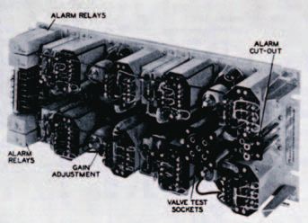
A Short History of Telecommunications Transmission in the UK

the development of highly efficient FDM carrier systems
was assisted by the mathematical analysis of J R Carson                                             frequency, they were controlled by a 60 kHz
                                                                                                    pilot signal from a single network source.
and was known as ‘suppressed carrier, single sideband’                                                   The theory of transmission lines
                                                                                                    comprising a central conductor surrounded
working                                                                                             by an outer cylindrical conductor, both
                                                                                                    running along the same axis, e.g. a coaxial
                                                                                                    cable, had been studied by a number of
television signals, were carried on the            Laboratories, of ‘negative feedback’. This       Victorian scientists including Heaviside,
transmission network. Hence transmission           required the insertion of part of the output     Kelvin and Rayleigh. But the concept of its
performance became evermore complex                signal from the amplifier into its input in      use as a bearer for long-distance FDM
with time.                                         reverse phase8. The passive feedback             transmission systems was patented, in 1929,
                                                   network had a loss/frequency characteristic,     by Affel and Espenschied of the Bell
                                                   which made the overall performance of the        Laboratories. In the UK, a fully engineered
Capacity Breakthrough – the
                                                   amplifier immune to changes to amplifier         FDM coaxial route was field trialled and
Rise of Frequency Division                         components and provided a high degree of         opened for traffic in 1938 on the London –
Multiplexing                                       stability and linearity.                         Birmingham route and extended to
                                                       At the CCIF meeting in Oslo in 1938,         Manchester in 1940. The cable contained
The major breakthrough in the search for           contending proposals for channel spacing         four coaxial cable tubes of 0.45 inch inner
more economical transmission came with             on international transmission systems were       diameters. Two were used for telephony
the development of carrier telephony. The          3 kHz and 4 kHz, the latter sponsored by         using a frequency band of 50–2100 kHz,
possibility of transmitting multiple signals       the UK9. The advantages of the wider             with 4 kHz channel spacing and providing a
over a common circuit using a different            transmission band, i.e. 300–3400 Hz instead      total of 400 channels. The other two tubes
frequency for each was first considered for        of up to 2700 Hz, were sufficient to lead to     were used for TV channels with a
telegraphy. Alexander Graham Bell became           the adoption of the 4 kHz spacing. The           bandwidth of 1.6 MHz. It is believed that
involved in telecommunications when                standard requires the channels to be             this was the first system in the world to
experimenting with mechanical resonance            assembled first as groups of 12 in the range     operate commercially and carry traffic on
to distinguish and separate different              60–108 kHz (or 12–60 kHz) and then, where        more than one supergroup11. This resulted
telegraph signals sent simultaneously over         applicable, as supergroups, in the range         in the development of standard systems for
the same pair of wires. However, Major             312–552 kHz (5 groups, 60 channels), before      installation on 3/8 inch coaxial cable with
George O Squier of the US Signal Corps is          translation to the line or baseband              6 mile spaced repeater sections to provide
attributed with inventing carrier telephone        frequencies. As higher capacity transmission     600 speech circuits in the band 60–
multiplexing in 1910, when he succeeded in         systems were introduced, 5 supergroups           2540 kHz. Later developments resulted in a
transmitting two simultaneous voice signals        were combined to form a 300 channel 512—         range of systems for the transmission of TV
over a single seven-mile long private              2044 kHz mastergroup. In the UK, an              signals. But by the end of the war (WWII)
telephone circuit. He termed it ‘wired             assembly of 15 supergroups in the range          only a few coaxial systems were installed
wireless’. AT&T who developed a                    312–4028 kHz (900 channels), known as a          (see Figure 611).
commercial system during the period 1914 –         hypergroup, was formed. It was the use of             By 1952, the long distance public trunk
1918 successfully contested his patent,            quartz crystal resonators in the filters, a      telephone network had doubled in size from
claiming that Squier’s work was only               technique discovered in 1931, which
‘suggestive’ and that its system was based         enabled the channels to be spaced at 4 kHz        Figure 6 Coaxial cable systems in
on inventions by its own engineers7.               with a well-defined passband and good                      the UK at 1946
     The development of highly efficient           audio frequency response.
frequency division multiplexing (FDM)                  Early carrier systems were limited to
carrier systems was assisted by the                open-wire lines, mainly in Wales and
mathematical analysis of J R Carson who            Scotland. But in 1935, the Post Office
demonstrated that modulation produced a            undertook a trial of cable and equipment for
carrier frequency with upper and lower             a 12-channel, non-loaded multi-conductor
sidebands and that it was sufficient to            carrier system between Bristol and
transmit only one sideband if the original         Plymouth10. The results justified
carrier frequency was reintroduced at the          expectations and 12-channel carrier sys-
demodulation stage. This was known as              tems became the normal means of providing
‘suppressed carrier, single sideband’              long distance trunk circuits. Eventually
working. Other significant developments            24-channel carrier systems were developed
included design of bandpass filters with           comprising the basic 12-channel group in
well-defined cut-off limits. In order to           the range 60–108 kHz plus another basic
accommodate the wide frequency range of            group modulated against a carrier of
carrier systems, cables needed to be               120 kHz to produce the band 12–60 kHz. It
unloaded and equalisers designed to give a         was known as Carrier System No 7, which I
reasonably flat frequency response over the        well remember working on at Canterbury
carrier frequency range. But a major               repeater station. Because the original
problem was the need to achieve stable,            carriers are suppressed they must be
linear amplification of the carrier signal.        introduced at the demodulating equipment.
The solution came, in 1927, from the               To ensure that the master oscillators at each
invention, by H S Black of the Bell                repeater station are synchronised to the same

The Journal of The Communications Network   • Volume 5 Part 1 • January–March 2006                                                                      33
A Short History of Telecommunications Transmission in the UK
that of the immediate post war period, to not practical due to the safety requirements used amplitude modulation of the VHF
18 000 lines of over 25 miles length. Early for high-voltage power-feeding. carrier. However, the major use of radio in
post-war coaxial systems comprised a few Compared to the transistor the valve is the UK network came about with the
2.5 MHz systems (60–2540 kHz, 600 very inefficient, requiring a power of watts exploitation of the microwave spectrum
channels). The first standard 4 MHz coaxial to provide an output of a few milliwatts, i.e. (300–3000 MHz). In 1931, there was a
system was designed by ST&C based on an efficiency of around about 0.1%. A good successful experimental link between Dover
their 2.6 MHz line-regulated system, which deal of development was carried out on and Calais (see Figure 912), operating at
used a pilot frequency to automatically vary valves to reduce their size and power 1700 MHz with a radiated power of 0.5 W12.
the line amplifier gain to compensate for consumption (see Figure 811). But valves By 1934 a 56 km microwave link was
changes in cable attenuation due to were inherently unreliable and frequently operation on a commercial basis between
temperature variations. Two such 2.6 MHz failed so that standby repeaters with the airports of Lympne in Kent and St
systems were used in the UK on the London automatic changeover were a necessity. Inglevert in France. The development of
– St Margarets Bay route (of which I The equipment was bulky and occupied microwave radar technology during the war
maintained the Canterbury – St Margarets a great deal of space, an intermediate made an important contribution to the
section) and a route in Northern Ireland. repeater occupied a full rack of equipment, design of communication exploitation of the
Previous systems used manually inserted and with today’s technology a single chip microwave band. In 1946, the BPO opened
fixed equalising networks. The 4 MHz would probably suffice. Most of the early its own 200 MHz frequency modulation
system had a capacity for 16 supergroups coaxial cables incorporated coaxial pairs of (FM) experimental link between London
(960 circuits) or a 405-line TV signal over 0.375 inch diameter and by the mid 1960s (Dollis Hill PO Labs) and Castleton, near
the band 60–4092 kHz, with 6 mile repeater around 5000 sheath miles had been Cardiff using rhombic wire aerials, it was
spacing, and was introduced in 1951. It was installed. At this time smaller diameter used for a time to provide the link for the
supplemented in 1961 by a 12 MHz system cables (0.174 inch) equipped with transistor opening, in 1952, of the BBC television
in the range 312–12 388 kHz with 2700 amplifiers accommodated in underground transmitter at Wenvoe, near Cardiff. It was
channels and a nominal repeater spacing of jointing chambers were introduced, later upgraded to 4 GHz using klystron valve
3 miles. The highest capacity coaxial cable achieving substantial economies. oscillators with which I was familiar in my
system used in the UK was the 60 MHz period as a radar mechanic with the RAF.
system (4404–59 580 kHz, 10 800 channels); The first commercial link, operating at
it was used for the London – Birmingham Mixed Media – the Use of 900 MHz, was established in 1949 from
route in 1980. In the early 1960s transistors Radio London to the first regional TV transmitter
became available and were used for 4 and at Sutton Coldfield, near Birmingham. The
12 MHz systems, enabling buried repeaters Marconi’s experiments with radio waves in Government’s decision to extend television
to be used with power feeding, thus avoid- the 1890s led to the widespread use of long- coverage from the London area to the rest of
ing the use of the small buildings tradition- distance radio communication for the UK by the 1950s stimulated the creation
ally used to house repeaters. Because valves telegraphy and by the mid-1920s the of the microwave radio network. However,
were used for repeaters, they had to be development of thermionic valve technology valve amplifiers operating at these high
housed in small buildings (see Figure 711) led to the introduction of radio-telephony. frequencies was a major problem, which
along the cable route, which sometimes Initially long waves were used but the more was solved by using the travelling wave
posed difficulties in finding suitable sites. efficient short wave radio services became valve amplifier, developed during the war. It
Housing valve amplifiers in manholes was the norm for long-distance international was first used in 1952, in the 4000 MHz
telephony services until the first trans- Manchester – Edinburgh (Kirk O’Shotts) TV
atlantic cable (TAT1) came into service in link, the world’s first operational use of the
Figure 7 Small coaxial cable travelling wave tube for a microwave
1956. In the 1930s VHF radio links, in the
repeater station range 50–100 MHz, were used to provide communications link13. From then on the
communication between the UK mainland microwave network was rapidly extended,
and offshore islands. A 40-mile 65 MHz link as shown in Figure 1012, initially for the 405-
comprising 15 telephone circuits was line 3 MHz monochrome television
provided between Scotland and Northern distribution network and then increasingly
Ireland and an 85-mile four channel link,
operating at 37.5 and 60 MHz, was provided
between Dorset and Guernsey. These links Figure 9 The St. Margaret’s Bay,
Dover, terminal of the
experimental link
Figure 8 HF amplifying valves,
1935, 1940 and 1945
34 The Journal of The Communications Network • Volume 5 Part 1 • January–March 2006A Short History of Telecommunications Transmission in the UK
Figure 10 BPO microwave radio-
relay network at 1980
Heritage declared it a national monument in of signal, e.g. speech, data, television,
2001. facsimile, to be carried on a common
When, in the 1980s, the UK network transmission path. Unfortunately its
was being transformed into an integrated practical implementation had to wait for the
digital network, it was necessary to availability of reliable mass-produced
introduce digital microwave radio systems transistors in the 1960s because valve
into the existing infrastructure of towers and technology could not meet the required
buildings. In the early 1970s, an switching speeds.
experimental microwave digital radio link Early PCM systems, in the late 1960s,
was established between Fairseat and were used in the junction network providing
Tolsford Hill, providing 6 bothway channels 24 channels on two pairs of wires using a
in the band 5850–5925 MHz, four operating gross bit rate of 1.536 Mbit/s. Most existing
at 6336 kbit/s and two at 2048 kbit/s. Given audio cables provided suitable pairs and
the existing use of the 4 and 6 GHz radio regenerators were provided at 1.83 km
network, it was decided to overlay them intervals, replacing loading-coils located at
with an 11 GHz digital radio network to these points. Power was fed to the
provide a rapid method of supplementing regenerators over the phantoms formed by
the digital line network to meet targets for the two pairs in each quad. Generally PCM
establishing an integrated digital network. systems were economical at route lengths of
The system provided 6 GO and 6 RETURN 10 to 16 km. It was decided that the
channels, in the range 10.7–11.7 GHz, each signalling units that interfaced the Strowger-
used for telephony expanding from 600 operating at 140 Mbit/s and providing 1920 type switching units should be incorporated
FDM channels to 960 and then 1800 telephone channels or two television into the PCM multiplexing equipment as
channels or a 625-line PAL standard colour channels. But whereas the performance of individual cards instead of costly relay sets.
television signal. By the late 1960s, the analogue systems was good, the digital Because of the variety of signalling facilities,
television distribution network had been systems fell well below expectations, par- 24 different types of signalling unit were
upgraded so that it could carry all colour ticularly on long hops. This was principally developed and, with all the other items such
signals; also solid-state techniques were due to inter-symbol interference stemming as regenerators, equalisers and alarm units,
beginning to take over from valve-based from multi-path propagation. The solution resulted in over 50 different items being
designs. The potential capacity of the UK was to use space diversity working on hop specified16. Some 7000 systems were
microwave network was extended when the lengths greater than 35 km with the addition installed in the UK, mainly in the junction
BPO was allocated the 2, 4, 6 (upper and of adaptive equalisers for distances over 50 network. Many difficulties had to be solved
lower), 11 and 19 GHz bands under the ITU km. It was also necessary to be more precise in introducing this equipment into the
International Radio Regulations. in aligning the antennas whose mounting hostile and noisy electromechanical
By 1980 microwave radio systems arrangements had to be strengthened to switching environment that could produce
carried 12% of all trunk network telephony achieve the necessary degree of rigidity to transient spikes at the interfaces in excess of
services and all long-distance television, maintain performance under bad weather 1000 V. However, the CCITT eventually
equivalent to a further 7% of trunk network conditions. This was followed by the produced a standard of 30-channel,
telephony capacity14. conversion of the 4 and lower 6 GHz bands 2.048 Mbit/s format using 8-bit A-law
The famous landmark and lynchpin of to digital working where propagation encoding for the primary level of the digital
the microwave network is the 620 ft high BT conditions were less severe than at 11 GHz transmission hierarchy. It was adopted for
Tower that was opened by the then Prime and higher capacities could be achieved. the UK network and was the interface to
Minister, Harold Wilson, on 8 October 1965. digital switching systems. But the CCITT
It replaced the existing radio terminal on the failed to gain full agreement on the standard
adjacent Museum telephone exchange Into the Digital Era and the USA adopted a 24-channel system at
building in Howland Street, London. It took 1544 kbit/s with 8-bit P-law encoding.
four and a half years to build at a cost of Although digital transmission systems, Unfortunately, it was found that the higher
£2.5m. During this period I was employed which used width or time-modulation of bit rate gave rise to crosstalk problems in
as a Clerk of Works, responsible for some individual pulses, had been studied in the many of the existing cables, which reduced
equipment in the Tower but primarily the 1930s, they produced no advantages over
trunk exchanges in the base building15. The FDM systems. It was Alec Reeves, born in
base building also contains the TV Network Redhill, Surrey, who in 1937 made the
an 11 GHz digital overlaid
Switching Centre, which carries TV pro- breakthrough with his invention of pulse
grammes for the BBC and other television code modulation (PCM). He was working in
radio network provided a
broadcasters and switches some programmes the Paris laboratories of Le Materiel
between the various regions. At the time it Telephonique at the time but with the
rapid method of supple-
was the tallest building in the UK, so that it outbreak of war, moved to the ST&C
could beam programmes over the Chiltern laboratories in England. PCM involves the menting the digital line
Hills that form the northern rim of the sampling of an analogue signal (at 8 kHz for
London basin and also to avoid tall speech) and the binary encoding of the network to meet targets
buildings in London. It is now the seventh sampled amplitude into 8-bit bytes thus
tallest structure in London and is a Grade 2 providing a digital signal that is virtually for establishing an inte-
listed building, which prevented its obsolete immune from noise, interference and most
horn aerials from being recovered. English forms of distortion. It enabled many forms grated digital network
The Journal of The Communications Network • Volume 5 Part 1 • January–March 2006 35A Short History of Telecommunications Transmission in the UK
by 1990 the trunk network,
switching and trans- was initiated. By 1980, the coaxial cable network and the emerging digital network
system of the UK network comprised some some use was made of supergroup and
mission, had been 30 000 sheath km of cable enclosing 207 000 hypergroup codecs, which could convert
coaxial tube km of which around 80% was these FDM levels into digital format without
converted to a wholly of the small bore 1.2/4.4 mm type and the the need to demultiplex down to the
rest 2.6/9.5 mm. With such a large coaxial individual channel level.
integrated digital network network it was natural that it should be Trouble-free digital transmission was
considered for conversion to digital use. It rather more difficult to achieve than the
– a world first for BT was decided that 120 Mbit/s was the theory led to believe. In fact, there was
maximum bit rate for the existing small bore nothing like a high-speed data stream for
the number of pairs that could be used for network and could use the same 2 km detecting noisy cable joints, poor earthing
PCM systems. Existing cable utilisation was regenerator spacing. The first systems at this and rack arrangements, unsuitable circuit
improved by the adoption of a new line code rate were introduced into the network in design or poor repeater station engineering.
that reduced the line rate without reducing 1980 with a capacity of 1680 telephony Such problems had minimum impact on
the information rate, but new transverse channels, assembled via 2–8 Mbit/s and 8– analogue transmission, but required
screened cables were also designed to 120 Mbit/s multiplex equipment to provide significant testing and investigation to solve
separate both directions of transmission to a total capacity of 1680 channels. A field when implementing digital. Repairs that
finally overcome the crosstalk problems17. trial was held on the Guildford – were adequate for FDM transmission proved
In the 1960s a multi-disciplined study Southampton – Portsmouth route and this to be quite unsuitable for time division
by the UK Trunk Task Force (UKTTF), using led to the ordering of around 100 systems in multiplex (TDM) and a considerable
extensive computer modelling, examined the period 1975–1979. Only a limited amount of testing and remedial work was
the future of the trunk network in terms of number of these systems were installed needed to bring, particularly older, cables
long-term customer requirements and the because BT subsequently adopted the up to the standard required for digital. For
costs of meeting them with the potential CCITT (now the ITU-T) recommended this reason and with the advent of fibre
technologies. Its conclusions were far- 140 Mbit/s with a hierarchy of 8 and optics, only a relatively small number of the
reaching, radical and, in hindsight, 34 Mbit/s. This was found suitable for the newer coaxial cables were converted to
remarkably accurate16. Its major small bore coaxial network by a change of digital working. However, by 1990 the trunk
recommendation was that the deployment the line code from 4B3T to 6B4T with network (see Figure 1219), switching and
of digital switching and transmission in an minimal changes to the regenerators16. transmission, had been converted to a
integrated manner would result in The carrier cable network comprised wholly integrated digital network – a world
significant cost savings and improved two-cable working, one for each direction of first for BT.
quality of service, as illustrated in transmission, each cable containing 24 pairs
Figure 1116. It would also provide a platform of 1.27 mm conductors, each pair carrying
for many innovative services. 24 channels multiplexed in the range 12– Lighting the Way
Following the recommendation of the 108 kHz. A total route length of 8000 km
UKTTF, in 1969, which recommended that existed, and to utilise this asset an Optical fibres were first considered as a
the BPO trunk network should evolve to a 8448 Mbit/s, 120-channel digital system was transmission media in 1966 by Kao and
fully integrated digital switching and developed and deployed to replace the Hockham20 and in 1969 where it was shown
transmission network, the development of carrier systems18. To reduce the cost of that very-low-loss optical materials
high-capacity digital transmission systems interworking between the legacy FDM
Figure 12 Digital trunk network
Figure 11 UKTTF cost projections for various network configurations at 1991
100
Space Switching with FDM Transmission
Digital Main Switching Unit
Network Interface Centre (NIC)
80 Flexibility Point
Earth Station
Relative Annual Charges
Microwave Radio
Fibre and Coaxial Cable Systems
Space Switching with Digital Transmission
60
Digital Switching with Digital Transmission
‘Integrated Digital Network’
40
0
0 100 200 300 400
Number of Trunk Exchanges
36 The Journal of The Communications Network • Volume 5 Part 1 • January–March 2006A Short History of Telecommunications Transmission in the UK
in 1981 the then world’s longest optical fibre link was
brought into service between London and Birmingham, experimental evidence showed that a low-
attenuation waveguide could be sub-
a distance of 204 km – it was also the first link in the stantially realised in practice. Furthermore,
it speculated that ‘... a frequency band
UK to operate at the long wavelength of 1300 nm ranging from 40 000 to 80 000 Mc/s may
become available on a single 2 inch
existed21. This, together with the lower loss, less than 0.5 dB/km. In 1980, a diameter waveguide, so providing a trunk
development of coherent optical sources, demonstration of a 37 km unrepeatered system, the bandwidth capabilities of which
and particularly solid-state gallium arsenide system of 140 Mbit/s at 1300 nm indicated would meet the largest demands of
(GaAs) lasers, led to the promise of optical the potential of the single mode approach. It communications engineers for the
communications systems. In 1970 the first was also realised that such systems were foreseeable future ...’ In the ensuing
20 dB/km glass fibre was announced and by well suited to undersea applications where discussion, which included Sir Archibald
1983 progressive development had reduced long repeater spacing was a prime concern, Gill, the Engineer-in-Chief, doubts were
this to less than 0.5 dB/km22. Although the and in 1980 a 10 km link working at expressed ‘... as to the wisdom of
advantages of single mode fibre were 140 Mbit/s was demonstrated at Loch Fyne, transmitting very large numbers of
recognised, the practicalities of fabricating, in collaboration with ST&C. The culmin- telephony channels on one repeater; there
splicing and coupling low-loss single-mode ation of this phase of research was field- was a general feeling about 1000 channels
fibres, with core dimensions of only a few installed single-mode fibre systems carrying was the maximum desirable ...’
microns, were that major problems needed digital signals up to 650 Mbit/s over Further research was carried out in the
to be solved. The requirement for rapid unrepeatered lengths as long as 60 km24. 1950s and 1960s by Bell Labs and BT who,
development of fibre technology meant that In 1981 the then world’s longest optical in an IPOEE lecture in 196026, estimated
the easier multimode fibre route was taken. fibre link was brought into service between that a 2.5 inch diameter circular waveguide
This resulted in the demonstration of an 8 London and Birmingham, a distance of with regenerators at 15 mile intervals would
Mbit/s system operating over a 6 km, step- 204 km. It was also the first link in the UK be capable of providing some quarter of a
index multimode fibre link at BT’s to operate at the long wavelength of million speech channels. It was considered
Martlesham research centre in 1975. This 1300 nm where the lower attenuation that the high growth of telephone, tele-
was followed, also in 1975, by a graded- allowed regenerators to be spaced at 10 km vision, telex and music traffic plus the
index multimode system operating at 140 instead of 8 km with the 850 nm earlier emergence of new data and facsimile
Mbit/s. In 1979, BT embarked on a major systems. The first system on the 8-fibre services would justify such capacity in the
ordering programme for proprietary (cable cable operated at 34 Mbit/s and was future and development should continue.
and equipment turnkey packages) followed in 1983 by a 140 Mbit/s system. The degree of interest in this technique had
multimode fibre systems operating at the From then on, fibre became the norm for also been demonstrated when, in 1959, the
800–900 nm wavelength, for trunk and trunk transmission systems both at IEE had organised an international con-
junction routes. Some 34 systems on 15 140 Mbit/s and, as demand grew, in- vention devoted to the topic.
different routes comprising 3600 fibre-km creasingly at 565 Mbit/s. A good deal of In 1974, BT held a field trial over a
were installed consisting of six 140 Mbit/s preliminary development work was carried 14 km route in Suffolk of a lightweight 5 cm
systems, four 34 Mbit/s systems, two 8 out for a 565 Mbit/s coaxial system, but it diameter wire helix waveguide. A group at
Mbit/s systems with 22 systems in the would have required regenerators at 1 km UCL under the leadership of Professor E M
junction network operating at 8 Mbit/s. In compared to the 30 km expected on optical- Barlow contributed with theoretical and
1981 sufficient confidence was achieved to fibre systems at that time, so work on the experimental studies. The overall
allow for a further 65 routes requiring project was ceased. Great difficulty was attenuation was less than 0.3 dB/km over
nearly 12 000 km of fibre including one 140 experienced with early designs of fibre the 30–110 GHz band, which would have
Mbit/s monomode route between Luton and connectors primarily in the manufacture provided a capacity of some 300 000
Milton Keynes. A third proprietary order for and maintenance of the high tolerances telephony or 200 television channels28. The
35 routes was placed in 1982. Resulting required to achieve the low-loss stable practical application progressed as far as a
from the experiences of the proprietary connectivity. feasibility study for a London – Bristol
systems, standard specifications were system but it was overtaken by the work on
produced to enable the separate purchase of optical fibre technology that offered a more
cables and equipment23. Waveguides – Overtaken by cost-efficient, flexible and ease of
Early optical fibre designs operated at Events installation alternative. This lead to the
850 nm because optical components were death of the waveguide for long-distance
easier to design at these shorter wave- The use of the waveguide as a transmission transmission.
lengths. A great deal of research was carried medium was recognised as long ago as 1897
out by the BT laboratories from the mid- when Lord Rayleigh had shown that, using
1960s including the development of trial Maxwell’s field equations, electromagnetic Service Protection Becomes
systems and a unique method of manu- waves could propagate inside hollow metal Important
facturing fibres, known as the double- tubes. In the 1930s a great deal of research
crucible method. Worldwide research had was carried out on centimetric waveguides As the capacity of transmission systems
indicated that the 1300 nm window of fibre within Bell Labs which was of considerable increased, the impact of system failure on
promised low loss and wide bandwidth, but value to microwave radar development the quality of service experienced by
needed new opto-electronic devices such as during the war as an aerial feeder, which I customers became more visible. The
semiconductor lasers and photodiode recall from my days in the RAF. In 1948, a flexibility of repeater stations allowed
detectors. This stimulated new research on paper was presented to the London Centre restoration of failures, particularly as the
single-mode technology that promised even of the IPOEE by W J Bray25, stating that network grew in size and became more
The Journal of The Communications Network • Volume 5 Part 1 • January–March 2006 37A Short History of Telecommunications Transmission in the UK
an improvement was required from the 90% of system
failures made good within a time of 20 minutes, errors known as slip. This synchronised all
2 Mbit/s exchange ports into the
achieved by the manually switched service protection transmission network28. In the mid-1980s
BT had recognised the advantages of
network, to the ITU-recommended target of making synchronous transmission networking and
had developed a product known as the
good 90% of failures within 10 seconds SMUX, which allowed sixty-eight 2 Mbit/s
time-slots to be synchronously multiplexed
meshed in its structure, but this was a time- it suffered many problems and delays which into 140 Mbit/s. It was successfully trialled
consuming exercise of many hours, postponed its being brought into service, in Northern Ireland but the product was
sometimes days. To minimise the impact of with reduced features, until about 1990. To abandoned when the synchronous digital
transmission failures, a system of compensate for development delays of the hierarchy (SDH) standard became available.
geographical diverse routings was used so ASDSPN, a simple form of automatic service The new standard was initially derived
that there was always a proportion of protection was employed on some of the in 1986 by Bellcore in the USA as SONET
circuits available. However, it was extremely more important transmission routes. The (synchronous optical network) and was
difficult to access the large volume of local introduction of SDH equipment with its closely followed by the ITU-T SDH standard
and national records to ensure that systems ability to form self-healing rings and meshes in 198829. Both are similar and allow for
on different cables did not, at some pinch- overcame the need for ASDSPN-type traffic interworking between them but not
point in the network, share the same duct equipment. the control functions. The standard is a
route. As the high-capacity coaxial synchronous multiplexing method with byte
expanded, manually patched standby line instead of bit interleaving and transport of
systems in a 1-for-N service protection Into the Synchronous Era – the PDH rates of up to 140 Mbit/s within a
network were used to improve availability. transmission rate of 155.52 Mbit/s.
Removing the Multiplexing
Microwave radio systems had an integral 1- Increased flexibility is provided by the drop-
for-N automatic protection switching Mountain and-insert function, down to the primary
system, which in addition to dealing with (2 Mbit/s) rate and also a remotely
system failures also provided a measure of The standards for digital transmission were controlled crossconnect between systems.
protection against transient and irregular defined in the late 1960s and early 1970s Probably the most powerful function,
propagation problems, such as multi-path when systems were introduced on coaxial however, is the management layer, whose
fading. cables. The features were constrained by the communications are transported within a
When the high-capacity digital network performance of the digital devices of the dedicated data communications channel,
was introduced, an equivalent 140 Mbit/s time and their cost. The multiplexing analogous to the signalling in a switched
digital service protection network was used. technique allowed for input rates that were network. This provides for a large number
But the increasing need for improved slightly non-synchronous, known as of remote-controlled automatic protection,
performance, stemming from the many plesiochronous, eventually leading to the restoration, provisioning, consolidation and
networks and services supported by the term plesiochronous digital hierarchy grooming functions. However, the
transmission network, required an (PDH). But the hierarchy is constructed transmission community were slow to
improvement from the 90% of system stage by stage from the 30 channels at develop these applications, probably due to
failures made good within a time of 20 64 kbit/s making up the 2 Mbit/s primary their lack of experience of software control,
minutes, achieved by the manually switched bit stream to 8 Mbit/s, 34 Mbit/s, compared to the switching community. The
service protection network, to the ITU- 140 Mbit/s, and 565 Mbit/s. Because of the add/drop feature enabled the construction
recommended target of making good 90% of complex framing and justification process it of self-healing rings, while the digital cross-
failures within 10 seconds27. Therefore, a was not possible to extract a 2 Mbit/s block connect enabled more complex resilient
contract was competitively placed in 1983, (or 64 kbit/s channel) from any level in the mesh networks to be constructed for the
for the design, supply and installation of an hierarchy without demultiplexing down the inner core of the transmission network. The
automatically switched digital service hierarchy. This gave rise to the very SDH hierarchy initially comprised levels at
protection network (ASDSPN). It comprised expensive ‘multiplexing mountain’. 155 and 622 Mbit/s, but grew to 2.5 and
a mix of distributed and centralised software By the 1980s it was evident that the 10 Gbit/s, and has now probably reach its
where a set of up to eight preprogrammed cost, reliability, poor performance- limit of 40 Gbit/s (roughly half a million
make-good plans were held for each monitoring features, and lack of flexibility voice channels on a pair of fibres).
transmission system together with the status were severe disadvantages of existing
of the protection and working systems. standards. Also there was a mismatch with
When a system failure was detected, the American standard of 1.5, 6, 45 and Wavelength Division
appropriate service protection systems, 140 Mbit/s. Furthermore, the developments
Multiplexing – a Return to
networked if necessary, were used to of optical fibre transmission and large-scale
replace the failure and report to a network integrated circuits made possible the FDM
management centre. If automatic make- creation of a more complex standard that
good plans could not be implemented, would be better suited to the demands of The most recent transmission development
alternative plans could be initiated future services. However, there was an has been wavelength division multiplexing
manually. It was a very ambitious project element of network synchronisation at the (WDM), which is an optical technique that
and, at the time, was probably one of the primary multiplexing level because, in the multiplexes a number of optical carrier
largest interactive computer networks in the integrated digital network, it was necessary signals on to a single optical fibre by using
UK with the same order of software as a to synchronise all digital exchange clocks to different wavelengths of light, i.e. colours,
System X digital exchange. Not surprisingly a high stability reference clock to prevent to carry different analogue or digital signals.
38 The Journal of The Communications Network • Volume 5 Part 1 • January–March 2006A Short History of Telecommunications Transmission in the UK
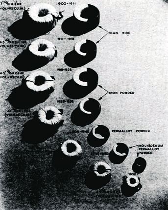
as demonstrated by Figure
This permits a very large increase in the of a wavelength between fibres, was
13, transmission develop-
capacity of a pair of fibres or bidirectional successfully demonstrated over three WDM
transmission over a single fibre. Ironically it channels in an optical star network on the
ments can be viewed as a
is a return to frequency division fibre ring that interconnected the London
multiplexing, since radio waves and light sector switching centres (SSCs), i.e. the
series of overlapping life
are both forms of electromagnetic radiation trunk and junction switching centres that
that can be described by their frequency or served the outer London sectors30.
cycles, each increasing the
the inverse wavelength. The possibility of Recent years have seen the rapid
WDM was recognised early in the development of WDM devices and improved
system capacity and
development of fibre due to the three widely fibre cables allowing for the emergence of
separated ‘windows’ of lowest attenuation, dense WDM where a large and increasing
reducing unit costs
i.e. 850, 1300 and 1550 nm wavelengths. In number of optical channels are available
the mid-1980s, BT specified that its supply together with optical add-drop multiplexers Theoretically, this figure could be increased
of single mode fibre should have both the and crossconnects. Modern DWDM systems by the use of 40 Gbit/s SDH but, at present,
1300 and 1550 nm windows available for can handle around 160 optical channels, dispersion problems limit the number of
use, in anticipation that WDM would which if supporting 10 Gbit/s SDH systems wavelengths that can be used for such
become commercially available. In 1991, a would result in a capacity of 1600 Gbit/s systems. A great deal of standards
coarse WDM system that employed (1.6 Tbit/s) over a single pair of fibres, i.e. formulation for WDM and fibre has been
wavelength routing, i.e. the crossconnection over 20 million 64 kbit/s channels. carried out by the ITU-T. But the excess of
Figure 13 Transmission life cycles
Digital and FDM
Digital Analogue and FDM Digital [WDM]
WDM
[< 20m]
[Capacity in Telephony Circuits] SDH Fibre
40 Gbit/s
[< 0.5m]
565 Mbit/s
FDM [7680]
10 Gbit/s
Coax 60 MHz [122 880]
12 MHz [10 800]
[2700]
140 Mbit/s 2.5 Gbit/s
4 MHz [1920] [30 720]
[960]
PDH
2.6 MHz Microwave Cable
[960] Radio
4 GHz 6 GHz
[240] 11 GHz
[1800]
Microwave Digital
FDM
Radio [24] [11 520]
Carrier
Audio 622 Mbit/s
Single Wire 2 Wire [1] Amplifiers [12] 1.5 Mbit/s PDH [7680]
[30] Fibre
Earth Return 4 Wire [1] 155 Mbit/s
Telegraphy [3] [400] [1920]
1900 10 20 30 40 1950 60 70 80 90 2000
Telegraphy First UK Fleming Reeves TAT 1 Kao Invents
Introduced Telephone Invents Invents Cable Optical
1838 Exchange Valve PCM 1956 Fibre
1879 1904 1937 1966
Bell Loaded Black Transistor Telstar
Invents Cables Invents Invented Satellite
Telephone 1902 Negative 1957 1962
1876 Feedback
1927
The Journal of The Communications Network • Volume 5 Part 1 • January–March 2006 39A Short History of Telecommunications Transmission in the UK
transmission capacity resulting from the forms), supported by the, now rapidly 10 Robertson J H. The Story of the Telephone.
burst Internet bubble has slowed the shrinking, UK telecommunications industry, The Scientific Book Club, 1948, p. 273.
deployment of DWDM. However, BT has a has been in the forefront of progress and
core meshed DWDM network and a number continues to lead the way. It has also made
of its competitors are also using DWDM. a major contribution to world tele- 11 Brockbank, R. A. and Floyd, C F. Wideband
High-capacity DWDM systems are expensive communications standards from the Transmission over Coaxial Cables. Institution of
The Post Office Electrical Engineers, February
and the size of system installed depends on inception of the standards forums. This 1946, Read Paper No 190.
capacity requirements and economics and at journal’s founding institution, in its 100-year
present up to 80 channels are used in the history, has chronicled these events in an
core network with 8–30 channels for accurate and readable manner.
12 Martin-Royle, R. D. and Dudley, L. W. A
backhaul. Systems with less than 8 active As the then President of the IPOEE, Brig Review of the British Post Office Microwave
wavelengths per fibre are generally known Sir Lionel H Harris, said in his Jubilee Radio-Relay Network. The Post Office Electrical
as coarse wavelength division multiplexing address, on 8th October 1956: ‘In this Engineers’ Journal, October 1976, 69(3).
(CWDM). It should be noted that current survey I have done no more than meander
DWDM systems only use a fraction of the through the activities and trends of what
capacity available on modern fibre. many of us believe to be the most 13 Jones, D. G. and Edwards, P. J. The Post Office
interesting branch of the most interesting Network of Radio-Relay Stations. The Post
Office Electrical Engineers’ Journal, October
profession. The detail will be found in past 1964, 57(3).
Conclusions and future numbers of our journal and its
contemporaries. The rightness or wrongness
Having commenced my BT career as a of our present thinking will come into the 14 Simpson, W. G. Transmission: An Historical
transmission man and returned to my limelight when we celebrate our Overview. The Post Office Electrical Engineers’
transmission roots after a period associated Centenary.’31 Journal, October 1981, 74(3) (75th
with planning the switched network, I was Anniversary Edition).
pleased to be invited to contribute this
article on the history of the UK transmission References
network: particularly since I had an article 15 Ward, K. E. The Heart that makes the Tower
published in the 75th anniversary edition of 1 Sir A. Mumford. Communications in the Public Tick. Post Office Telecommunications Journal,
Service of the UK. The Post Office Electrical Summer 1968.
the IPOEE journal. I have confined myself to
the main transmission network, ignoring the Engineers’ Journal, January 1964, 56(4).
local loop which, until the introduction of
16 Schickner, M. J. Digitalization of the Junction
broadband digital subscriber line (DSL) and 2 Transmission and the Trunk Network. The Post and Main Networks. The Post Office Electrical
fibre techniques, had remained immune to Office Electrical Engineers’ Journal, October Engineers’ Journal, October 1981, 74(3).
developments. I have also not dealt with the 1956, 49(3), 50th Anniversary Edition.
seminal developments in global trans-
mission, namely the first transatlantic cable 17 Dufour, G, Provision of Digital Transmission in
3 External Construction. The Post Office Electrical
(TAT1) in 1956 and the Telstar communi- Engineers’ Journal, October 1956, 49(3). the Junction Network. The Post Office Electrical
cations satellite in 1962 – both of which Engineers’ Journal, July 1981, 74(2).
changed the world forever. Nor have I
covered the unique use of cellular radio 4 Ward, K. Fleming and the Thermionic Valve.
The Journal of The Communications Network,
transmission that underpins mobile 18 Wright and Archer. 8.448 Mbit/s Digital Line
January–March 2006, 5(1), pp. x–x.
communication, which has had such a Systems on Carrier Cables. The Post Office
profound effect on our social life and habits. Electrical Engineers’ Journal, January 1982, 74(4).
Likewise I could also mention that the same 5 Williams, H. The New Amplifier No 32 and
bearer transmission systems (fibre/WDM, associated Equipment. The Post Office Electrical
etc) now support the Internet as well (i.e. Engineers’ Journal, July 1941, 34(2). 19 Reid A. B. D. Defining Network Architecture
for SDH. Journal of the Institution of British
packet switching as well as the legacy
Telecommunications Engineers, July 1991, 10(2).
circuit switching) and will be an indispens- 6 Turner, D. and Neill, T. B. M. The Principles of
able part of BT’s new IP network (21CN). Negative-Impedance Converters and the
As demonstrated by Figure 13 on the Development of a Negative-Impedance 2-wire
Repeater. The Post Office Electrical Engineers’ 20 Kao, K. C. and Hockham, G. A. Dielectric
previous page, transmission developments Fibre surface Waveguide for Optical
Journal, October 1958, 51(3).
can be viewed as a series of overlapping life Frequencies. Proceedings of IEE, 1991, 113, p. 1,
cycles, each increasing the system capacity 151.
and reducing unit costs. History has shown 7 Schwartz, M. Origins of Carrier Multiplexing –
that developments have moved the Major George Owen Spier and AT&T.
transmission network from early days when CHE2004, IEEE, June 2004.
21 Jones, M. W. and Kao, K. C. Spectrophoto-
its costs were dominant to today where metric Studies of Ultra Low Loss Glass. J Sci
distance is largely irrelevant. The impact on Inst, 1969, 2, p. 331.
8 Bray, J. Innovation and the Telecommunications
tariffs has had a major effect on customers, Revolution: from the Victorian pioneers to
moving telecommunications from an broadband Internet. Published by the IEE, 2002.
expensive luxury to an indispensable part of 22 Martin-Royle, R. D. and Bennett, G. H. Optical
Fibre Transmission Systems in the British
our life-style. 9 Halsey, R. J. The Economic Usage of Broadband Telecom Network: An Overview. Journal of the
Throughout the history of transmission Transmission Systems. The Post Office Electrical Institution of British Telecommunications Engineers,
R&D, BT (during its various organisational Engineers’ Journal, October 1958, 51(3). January 1983, 1(4).
40 The Journal of The Communications Network • Volume 5 Part 1 • January–March 2006You can also read