A Sketching Interface for Modeling and Editing Hairstyles
←
→
Page content transcription
If your browser does not render page correctly, please read the page content below
EUROGRAPHICS Workshop on Sketch-Based Interfaces and Modeling (2005)
Takeo Igarashi, Joaquim A. Jorge (Editors)

A Sketching Interface for Modeling and Editing Hairstyles

                                                          Shahzad Malik

                             Department of Computer Science, University of Toronto, Toronto, ON, Canada
                                                      smalik@cs.toronto.edu

    Abstract
    This paper presents interaction techniques and algorithms for modeling and editing virtual 3D hairstyles with a
    user-friendly sketching interface. Using a pressure-sensitive tablet, a user makes freeform strokes to mimic a num-
    ber of real-world hairstyling operations such as cutting, combing, curling, frizzing, and twisting. Additionally, the
    user can perform other localized operations such as implanting new hair strands onto a 3D surface (usually the
    scalp), lengthening the strands, and adjusting hair density. Virtual hairpins can also be placed onto strands to
    temporarily fix the position of hair which allows for the creation of more advanced styles such as ponytails. The
    system runs at interactive rates, thereby providing instant visual feedback to users as they work. Unlike existing
    hair modeling systems that require hours of complicated control point manipulations and parameter tweaking, our
    interface allows for creating expressive hairstyles quickly and easily, even for first-time users.

    Categories and Subject Descriptors (according to ACM CCS): I.3.5 [Computer Graphics]: Computational Geometry
    and Object Modeling - Modeling Packages; I.3.6 [Computer Graphics]: Methodology and Techniques - Interaction
    Techniques.

                                                                     and intuitively using a sketching interface. Using a tablet
1. Introduction                                                      the user draws freeform strokes on and around a 3D head
                                                                     model to perform a number of hairstyling operations such
With computer-generated virtual characters now appearing             as cutting, combing, curling, frizzing, and twisting. Due to
in everything from blockbuster Hollywood films to 3D                 the volumetric nature of hair, we leverage the pressure-
computer games, it is extremely important that these                 sensing capabilities of tablets in order to quickly and flu-
virtual humans each have their own unique identities and             idly access different layers of hair. In addition to the styl-
characteristics. It can be argued that hair is one of the            ing operations, hair can be implanted onto the 3D head,
most important physical attributes that we use to                    strands can be lengthened, and hair density can be modi-
differentiate and characterize those around us, so it seems          fied, all using simple command strokes. Finally, sections
reasonable to assume that virtual characters should be               of hair can be temporarily fixed in certain positions using
created with equally realistic and varying hairstyles.               virtual hairpins so that advanced styles such as ponytails
   While researchers have made significant advancements              can be created.
in realistic virtual hair synthesis from a rendering and               Figure 1 shows two hairstyles each created with our sys-
animation standpoint, modeling hair is still a difficult and         tem in less than two minutes by an experienced user.
time-consuming process. This is largely a consequence of             Unlike most commercial 3D hair modeling tools that re-
the complex properties of hair, such as the large number of          quire time-consuming control point manipulations and
strands (typically 100,000 on an average human head),                parameter tweaking, our techniques are designed to allow
artificial styling techniques (gel, mousse, curlers, hairpins,       exploration of a variety of hairstyles quickly and easily
etc.), and external forces (such as hair-hair collisions, hair-      during the character design process. Our informal user
head collisions, gravity, and static charge).                        feedback shows that even first-time users can create inter-
  In this paper we present a set of interaction techniques           esting hairstyles after only a few minutes of use.
for modeling realistic and expressive hairstyles quickly

© The Eurographics Association 2005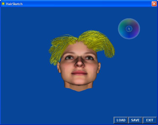
S. Malik / A Sketching Interface for Modeling and Editing Hairstyles

                                                                     attributes such as hair root position, density, and hair
                                                                     length can be established. While the system allows inter-
                                                                     esting hairstyles to be created fairly quickly, there are still
                                                                     some shortcomings. From a user interface perspective,
                                                                     having to draw in a 2D canvas window while observing
                                                                     the corresponding changes in a 3D view can be confusing
                                                                     as well as inefficient, since it requires the user to continu-
                                                                     ously change the focus of attention. Additionally, drawing
                                                                     on the flattened 2D representation of the head does not
                                                                     allow for accurate hair placement or hair orientation since
   Figure 1: Hairstyles created in less than two minutes.
                                                                     the mapping between the 2D and 3D views is indirect.
                                                                     This results in the user having to frequently make guesses
2. Related Work                                                      as to where a point on the 2D canvas maps to the 3D view.

The graphics community has been interested in virtual hair              Instead of manipulating individual strands or clusters,
modeling, animation, and rendering for the past two dec-             the vector-field and fluid-flow hair systems presented in
ades [MHK00]. Unfortunately most hair modeling sys-                  [Yu01] and [HM00] propose a radically different approach
tems described in the graphics literature make use of the            to hair modeling. A user interactively places a number of
ubiquitous Windows, Icons, Menus, and Pointers (WIMP)                field primitives such as streams, sources, and vortexes
paradigm for their user interfaces. Thus for explicit hair           around a 3D head. These primitives are then used to con-
modeling systems, where hair strands are defined indi-               trol the growth direction of hair emanating from the scalp
vidually, the user is required to manipulate control curves          in a post-process. While the final rendered results are
for each strand using the mouse in a graphical interface in          impressive, these field-based approaches make it almost
order to generate a full head of hair [DM93]. Cluster/wisp           impossible to generate artificial effects such as braids or
hair systems [WS92, XY01, KN02] are somewhat more                    ponytails. Additionally, the hair generation process takes
efficient from a user interface perspective since they re-           a significant amount of processing time, so it is difficult to
quire a user to only specify the control curve for an entire         determine how the final hairstyle will look just from the
group of strands contained within a cylindrical region. In           positioning of the primitives.
both cases, manipulating these control curves usually re-               Recent work has shown that it is possible to capture hair
quires the user to edit control points in 3D space using a           from multiple images of a real hairstyle using computer
combination of viewpoints (perspective, side view, top               vision techniques [GSML02, PBS04, WOQS05] which
view, front view), along with setting properties such as             opens up the possibility of completely automating the hair
hair colour, density, or length using dialog boxes, pull-            design process. While the current results are impressive,
down menus, and scroll bars/sliders. As a result, many of            the systems require about an hour of processing time to
these systems are extremely difficult to use without sig-            reconstruct the hairstyles. Additionally the existing sys-
nificant training, and even experienced artists typically            tems have difficulty capturing complex styles such as
require a few hours to design a detailed hairstyle. To               spiky hair, braids, or ponytails. Therefore efficient inter-
make matters worse, the real-time editing windows in                 active tools are still required to complement these com-
many of these applications usually only depict a coarse              puter vision techniques in order to enhance or modify the
wireframe outline of the strands that is not representative          captured styles.
of the final hairstyle. While a few do provide some                     Our hair sketching interface is motivated by recent work
higher-level editing operations such as cutting [LK01],              that shows intuitive techniques for the rapid exploration
combing [KN00], or curling, twisting, and braiding                   and design of 3D models [IMT99, TBSR04], clothing
[KN02], they still rely on the user to perform these opera-          manipulation [IH02], garment design [TCH04], and char-
tions with a standard 3-button mouse which is cumber-                acter animation [Osh04]. Mao et al. [MKKI02, MKIA04]
some and unintuitive. Many of the popular commercial                 were the first to show freeform strokes being used to
hair editing tools and plug-ins available today implement            model hair, but their system is extremely limited in the
variations of the WIMP-based interfaces as described                 hairstyles it is capable of generating since all hairstyles are
above.                                                               assumed to be symmetric about a partition line located at
  Only recently have researchers considered developing               the center of the top of the scalp. In other words, the user
more user-friendly interactive tools for modeling virtual            draws a partition line on the scalp, followed by a single
hair. The HairPaint system described in [HR04] presents              silhouette line on one side of the head. The system then
an alternative approach to modeling an explicit hair model           generates a symmetric hairstyle based on these input
by using a familiar 2D painting interface combined with a            strokes. As a result, short hairstyles such as a Mohawk are
set of color scale images to specify hair characteristics.           impossible to create with their system. Also, fine editing
Therefore by drawing in some particular color on a flat-             of the generated hairstyles is not possible since hair is
tened 2D representation of a 3D head model, geometrical              generated in a single shot. In contrast, our system allows

                                                                                                 © The Eurographics Association 2005.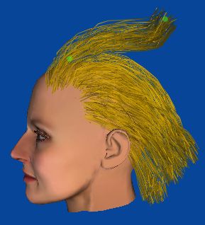
S. Malik / A Sketching Interface for Modeling and Editing Hairstyles

for hair to flow in any user defined direction and without               The second cluster parameter is twist, which is a rotation
any restrictions on how the hair strands are distributed on           value (in degrees) set per control point. This twist parame-
the scalp. Additionally, our system allows for advanced               ter allows cross-sections of the cluster to be rotated about
editing operations to be performed at any time such as                the corresponding control point as shown in Figure 4 and
lengthening, cutting, combing, curling, frizzing, and twist-          Figure 5.
ing.

3. Hair Representation
                                                                                                        control points
In our system, hair is represented using clusters as first                                              with twist
proposed in [XY01]. Therefore large groups of strands                                                   parameters
can be manipulated simultaneously by simply adjusting
the control curve for the cluster that contains them (Figure
2).    We use generalized cylinders to represent the                                                    control curve
boundary of hair clusters, while 3D Catmull-Rom splines
are used to represent the underlying control curve since                                                root
they guarantee that the curve will pass through the
corresponding control points. The control curve passes
through the center of the generalized cylinder, with the                   Figure 4: Twisting is specified at each curve control
root of the control curve located on some surface (usually              point (except the root), allowing strands to be locally ro-
the scalp of a 3D head model). We assume the polyline                                 tated about the control curve.
consisting of the curve control points has equal length
segments of 2cm, which provides a nice tradeoff between
curve smoothness and efficient processing time for
interactive control.

                                       hair cluster

                                       control curve

                                       hair strand                        Figure 5: (Left) Cluster with twisting set to 0; (Right)
                                                                        Cluster with twisting set to 45 degrees for every control
                                                                                                  point.
                                                                         Hair clusters also have a frizziness parameter ranging
                                                                      from 0 to 1 that is used to control the amount of shape
   Figure 2: A group of strands is contained within a hair            variation of strands within the cluster. A frizziness of 0.0
      cluster whose shape is controlled by a curve.                   denotes no shape variance, while a value of 1.0 denotes
                                                                      high shape variance (Figure 6).
   Each cluster has a set of parameters that affect the dis-
tribution of the strands contained within it. The first pa-
rameter is density, which ranges from 0 to 1. A density
value of 0.0 denotes no hair strands inside of the cluster,
while a value of 1.0 denotes a maximal number of hair
strands (Figure 3). We currently set the maximum number
of hair strands per cluster to 512, which works reasonably
well for our fixed-size clusters with a radius of 1cm.
                                                                         Figure 6: (Left) Cluster with low frizziness (0.1); (Right)
                                                                                   Cluster with high frizziness (0.9).
                                                                        Based on these parameters, hair strands can be generated
                                                                      inside of each hair cluster using the following equation:
                                                                                                                    k

    Figure 3: Left to right: low density cluster (0.1), me-                           p k = twist (c k + d k , ∑ θ i )
   dium density cluster (0.5), high density cluster (1.0).                                                         i =1

© The Eurographics Association 2005.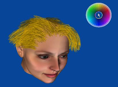
S. Malik / A Sketching Interface for Modeling and Editing Hairstyles
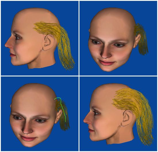
where pk is the k-th control point for some hair strand, ck which consists of the 3D head model, a cursor, and three
is the k-th control point for the control curve, dk is a dis- buttons (load, save, and exit).
placement from ck, θk is the k-th twist value in degrees,
and twist is a function to rotate ck+dk about the axis
formed from ck-1 to ck.
The displacement dk is computed iteratively similar to
the approach described by Choe and Ko [CK05]:
Figure 7: The cursor changes dynamically based on sty-
d k = d k −1 + e lus position and/or pressure. From left to right: default
cursor, implanting cursor, cutting/density cursor, styling
where e is a noise vector. To ensure that |dk| is less than cursor, and color selection.
the radius r of the cluster, we compute e=yx, where x is a
random unit vector and y is randomly chosen from the
range [0, min(L,σ·r)] where L is the intersection of the
vector e with the cluster’s generalized cylinder, and σ is
the cluster’s frizziness value.
Note that we still need to compute the initial displace-
ment of hair strands d0. Assuming the root position c0 of
the control curve is located on the surface of a 3D head
model, we uniformly distribute the desired number of
strand root positions p0 (based on the density parameter)
around c0 so that they remain within the cluster’s radius.
To guarantee that these new strand roots emanate from the
scalp as well, we use a pre-computed distance field [JS01].
A distance field provides a fast lookup of the distance and
gradient to the closest point on a 3D model for some query
point. Therefore for each new strand root position p0, we
determine the distance d to the closest point on the 3D Figure 8: A snapshot of the hair sketching interface.
model, and if the distance is not zero we extract the gradi- The cursor is currently in hair color selection mode.
ent ∇ to the closest point and set the strand’s new root
Hairstyling operations are performed using the tip of the
position to: stylus with varying amounts of pressure. Ramos et al.
p new = p 0 − d∇ [RBB04] showed that dividing the pressure range of a
tablet into six or less discrete levels instead of using it as a
The distance field is also used in a similar manner to pre- continuous value produces the best user performance and
vent cluster and strand control points from penetrating the control. We leverage this information by defining three
3D head model. equal pressure levels for performing styling operations in
different layers of hair:
4. Hair Sketching User Interface Level 1 (light pressure): Styling operations occur on the
hair cluster closest to the stylus tip’s cursor position in the
In this section we describe the hair sketching interface perspective view. The closest cluster is determined by
from a user’s perspective, along with the corresponding casting a ray through the cursor position in the viewing
algorithms for creating and styling hair clusters. We plane, and computing the closest intersection point with a
assume the system is being used with a pressure-sensitive hair cluster.
tablet along with a stylus that has at least one button along
Level 2 (medium pressure): Styling operations occur on all
its edge and a pressure-sensitive eraser tip. The interface
hair clusters that are intersected by the ray cast through the
features a single perspective view of a 3D head model that
stylus tip’s cursor position. The intersection point with the
can be rotated using the virtual trackball technique
3D model is also computed, and only clusters between the
described in [Hul90] by pressing the button on the edge of
viewer and the 3D model are considered.
the stylus. The tablet input space is mapped such that the
corners of the interface window are mapped to the corners Level 3 (heavy pressure): Styling operations occur on the
of the tablet. Hair is rendered on the 3D head model in surface of the 3D model.
real-time with realistic lighting and shadows to provide In all cases, the pressure level and affected clusters are
instant feedback on the results of styling operations. The determined based on the average pressure at stroke
shape of the cursor in the interface window dynamically locations within 2 pixels of the stroke’s start position.
changes based on the action the user is performing (see Therefore as a stroke is drawn, subsequent changes in
Figure 7). Figure 8 shows a snapshot of the user interface,
© The Eurographics Association 2005.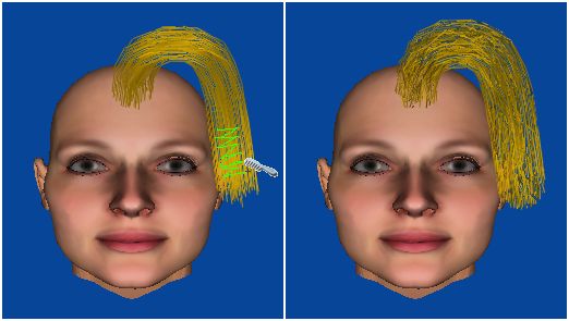
S. Malik / A Sketching Interface for Modeling and Editing Hairstyles
pressure do not alter the pressure level that was detected at subsequent clusters (which users typically draw close to
the start of the stroke. previously placed clusters) can be created with single
In the following sections we describe how the user can implanting strokes without the need for detailed styling. If
interactively implant hair onto the head, lengthen and cut there are no nearby clusters with similar 2D control
strands, adjust hair density, and style/comb hair in various curves, the new cluster is created assuming the 3D curve
ways. The user is provided with continuous visual lies in the view plane, with the depth value based on the
feedback based on the position of the cursor and the position of the cluster’s root on the scalp. Figure 9 shows
pressure of the stylus on the tablet. the benefit of this feature.
(a) (b)
4.1 Hair Implanting
To place hair onto the 3D head model, the user moves the
cursor tip to the desired location on the scalp from which
strands should emanate. With the pressure at level 3, the
user then draws a freeform stroke that defines how the hair
should flow. When the tip of the stylus is raised above the
tablet surface, the root position r of the cluster is (c) (d)
determined by computing the intersection point between
the 3D head model and a ray going through the stroke’s
start position on the image plane. The system then
generates a hair cluster that follows the user defined curve
as shown in Figure 8.
Figure 9: 3D curve estimation based on neighboring
hair clusters: (a) An initial cluster viewed from the side;
(b) A front view of the initial cluster; (c) A 2D stroke is
drawn from the front view that flows similarly to the initial
cluster; (d) The new 3D cluster flows similarly to the ini-
tial cluster.
Before converting the 2D input stroke into a 3D
Catmull-Rom spline, the input stroke is first converted into
Figure 8: Implanting a hair cluster. a 2D polyline with equal length segments. All other
existing hair clusters are then transformed into camera
In the case where the selected scalp location lies within space and projected into image space. The new cluster’s
an existing hair cluster, the existing cluster is deleted and a first spline control point c0 is then set to r, while
new cluster is created in its place based on the input subsequent control points ci are computed iteratively as
stroke. follows:
Visual feedback is provided to the user based upon the Extract the endpoints of the 2D polyline segment
pressure level. At pressure level 3, all existing hair on the
p i −1 and p i .
3D model is rendered semi-transparently so that the scalp
is visible. All new clusters are created with a fixed radius, Compute the normalized orientation vector p̂i for the
and the user can see an approximate outline of the cluster’s
position and dimensions on the scalp surface before polyline segment p i −1 p i .
beginning the stroke. From each cluster j, find the closest control point d aj to
Converting a 2D stroke into a 3D curve for the hair
cluster is an illposed problem, since there is an entire ci −1 in camera space below some maximum distance τ,
family of 3D curves with different depth variations that if one exists.
can all map to the same 2D stroke. To remedy this Compute the 2D image points q aj −1 and q aj by
ambiguity somewhat, we assume that hair exhibits some
spatial coherence. Therefore, if there are other hair projecting d aj −1 and d aj .
clusters closeby that have control curves which flow in
Compute the normalized orientation vector q̂ j for the
similar directions to the user-drawn 2D stroke, then the
system averages the 3D orientation of those nearby 2D vector q aj −1q aj , discarding those vectors with zero
clusters to determine the 3D representation of the new hair length.
cluster. This allows for faster sketching of new clusters,
since an initial cluster can be positioned as desired using
detailed styling strokes (as described in Section 4.5), while
© The Eurographics Association 2005.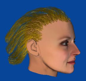
S. Malik / A Sketching Interface for Modeling and Editing Hairstyles
If the angle θi between p̂ i and q̂ j is above some
threshold (we use 30 degrees), we discard the
corresponding d aj −1 and d aj control points.
Using all other N remaining closest control points, we
compute Figure 10: Lengthening a hair cluster.
c i ( z ) = c i −1 ( z ) + bi p i − p i −1
4.3 Cutting Hair
where
Hair can be cut by drawing a relatively straight stroke
⎡⎛ c − d aj ⎞ ⎛ j ⎞⎤ across the boundary of a hair cluster using the pressure-
⎟ cos(θ )⎜ d a ( z ) − d a −1 ( z ) ⎟⎥
N j
⎜1.0 − i -1
∑j ⎢⎜
⎢
τ ⎟ i
⎜ d j −d j ⎟⎥
sensitive eraser tip. The stroke must start on one side of
the cluster and then exit on the other side in image space in
⎣⎝ ⎠ ⎝ a a −1 ⎠⎦
bi = order for the cutting operation to be performed. The cut-
N ⎛ c i -1 − d a ⎞
j
ting operation effectively works by computing the inter-
∑j ⎜⎜1.0 − τ ⎟⎟ section between the drawn stroke and a cluster’s control
⎝ ⎠ curve in image space (Figure 11). At pressure level 1,
only the closest hair cluster that is intersected by the stroke
in the perspective view is cut. If the stroke is drawn at
In the case where there are no valid nearby control pressure level 2, all clusters that are intersected by the
points from other clusters, set c i ( z ) = c i −1 ( z ) . stroke down to the scalp are cut. A cutting stroke at pres-
sure level 3 completely removes any hair clusters inter-
Back project the image point at p i using c i ( z ) as the sected on the scalp surface. Before a cluster is cut, its
depth value to retrieve the 3D coordinates for ci. existing hair strands are removed. After the cut, a new set
The basic idea behind this algorithm is to compute a of hair strands is computed based on the existing cluster
weighted average of the depth variations of neighboring parameters, as described in Section 3.
clusters that flow in a similar direction to the input stroke
intersected
(in 2D). This weighted average can then be used to image clusters
compute the depth variations for the new cluster. Note plane
that our formulation interpolates depth values linearly in
image space, which is inaccurate. However, for our
chosen control curve segment lengths we have found this
approach to work sufficiently well in practice.
Once the control points for a new cluster have been
determined, a simple smoothing operation is performed to cutting
eliminate sharp angles in the corresponding 3D polyline. camera stroke
Individual hair strands are then generated from the control
curve as described in Section 3.
Figure 11: Cutting hair clusters.
4.2 Lengthening Hair
4.4 Controlling Hair Density
Existing hair clusters can be lengthened by placing the
cursor near the end of the desired cluster and drawing a By default, all new hair clusters are created so that their
stroke with pressure level 1. For visual feedback, the density is a weighted average of the densities of
closest cluster becomes highlighted with a green tint as neighboring hair clusters. The weight assigned to each
soon as pressure is applied to the tablet, to help the user neighbor is based on the distance between the root
determine the end position of the cluster. When the stylus positions so that closer clusters are weighted higher. In the
tip is raised above the tablet surface, the system grows the case where there are no proximal clusters, density is set to
cluster so that it follows the path of the drawn stroke a default value of 0.5. To interactively increase the
(Figure 10). As with implanting, the lengthened 3D density of hair on existing clusters, the user draws a
segments of the cluster are determined by averaging any clockwise circular stroke with the eraser tip. At pressure
existing nearby clusters that have similar 2D control level 1, the hair cluster closest to the center of the drawn
curves. circle in the perspective view has its density value
increased by a fixed amount (we currently use an
increment of 0.05). A counter-clockwise circle decreases
the density value. At pressure level 2, all clusters
© The Eurographics Association 2005.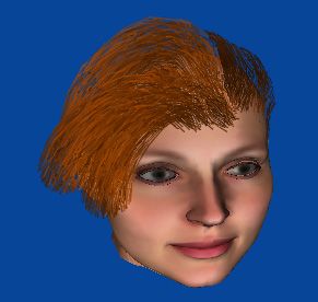
S. Malik / A Sketching Interface for Modeling and Editing Hairstyles

contained within the drawn circular stroke have their
densities increased or decreased. Finally, at pressure level                                                    twirl stroke
3 only the clusters emanating from the scalp area that falls
inside of the drawn circle have their densities increased or                                                    control curve
decreased. Similar to the way cutting works, hair density                      twirl overlap
adjustments are accounted for by first removing all hair
strands from the cluster and then recomputing new strands
as described in Section 3 (which takes the new density
parameter into account). Unlike previous operations,
however, density adjustments are performed each time a
full circle is drawn, regardless of whether or not the stylus
has been raised off of the tablet surface (Figure 12).
                                                                           Figure 13: Twisting hair. Each overlap of the twirl
                                                                       stroke contributes a 15 degree rotation to the closest con-
                                                                                        trol point for the cluster.

     Figure 12: Adjusting hair density. A full circle estab-
lishes density adjustment mode, while subsequent circles in
        the same stroke continuously modify density.

4.5 Styling Hair

Our system allows a user to perform a number of advanced
styling operations on an existing set of clusters to refine
the look of a hairstyle. The first such styling operation is
twisting, which causes strands in a cluster to locally rotate
about the cluster’s control curve as described in Section 3.
The twisting parameters for a cluster can be interactively                                 Figure 14: Frizzing hair.
modified by drawing a twirl stroke with the tip of the                   Hair can also be combed or curled by drawing smooth
stylus as shown in Figure 13.           When the stroke is            strokes that act as forces which push or deform the control
completed, the system first determines the clusters to                curve of the underlying hair clusters in the viewing plane.
affect based on the stroke’s start position and the pressure          Since such combing strokes are similar to those used to
level. The system then determines the points where the                implant hair, pressure is used to determine what action the
stroke overlaps itself. For each of these overlap positions,          user wishes to perform. At pressure level 1, combing only
the distance to the closest control point in each affected            affects the cluster closest to the start of the stroke in the
cluster is found. If an overlap position falls within the             viewing plane, while at pressure level 2 all clusters that are
silhouette of an affected cluster, the closest control point’s        intersected by the ray through the start of the stroke are
twist parameter is adjusted by 15 degrees. A clockwise                affected. Pressure level 3 is used to implant hair on the
twirl stroke increments the twist parameter, while a                  scalp as described earlier.
counterclockwise twirl stroke decrements the twist.                      To deform the control curve of affected clusters, the
Therefore by adjusting the frequency of twirls the strength           system first converts the input stroke into a polyline with
of the twisting can be interactively controlled.                      uniform length segments of size ρ (we currently use ρ=30
   Frizzing is a hairstyling technique used to introduce              pixels which works quite well). Each segment of this
small, tight curls onto individual strands. In our system             polyline then acts as a force vector that slightly nudges
the user can control the frizziness parameter of a hair               cluster control points located within ρ pixels from the
cluster by drawing a scribble stroke as shown in Figure 14.           segment start position. Let vi represent the normalized
The affected clusters are determined based on the pressure            direction vector for segment i of the input stroke, and qi
level and position at the start of the scribble stroke. If the        the start position of segment i. Let cj represent the j-th
average amplitude for the scribble is greater than or equal           control point of an affected cluster (not the root), and let pj
to the projected diameter of the affected cluster, the                represent the projection of cj on the image plane. We first
frizziness is set to 1. If the average amplitude is less than         compute the distance d between qi and pj. If d > ρ then
or equal to one-quarter of the projected diameter, the                we consider pj to be out of the influence range of vi. If it
frizziness is set to 0. All average amplitudes in between             is less than ρ, we compute w=1.0-d/ρ as the attenuated
these extremums linearly map to intermediate frizziness               force magnitude. pj is then displaced by wvi as shown in
values. Unlike twisting, frizzing adjustments affect a                Figure 15, and then back projected to compute a new cj
cluster globally as outlined in Section 3.                            (using the depth value of the original cj). After all control

© The Eurographics Association 2005.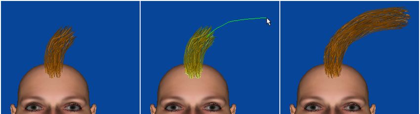
S. Malik / A Sketching Interface for Modeling and Editing Hairstyles

points for a particular cluster have been displaced by the
appropriate force vectors, the system performs relaxation
steps on the control curve’s polyline so that segment
lengths are approximately uniform and there are no sharp
angles. Adjustments are also made to prevent penetrations
with the 3D model as discussed in Section 3. Finally, hair
strands are regenerated for the entire cluster based on the
cluster parameters.
  While the current approach of using fixed-size segments
for our combing forces works well in most instances, there
is a tradeoff to be made with respect to speed and
accuracy. Clearly, we could use much larger segments to
increase speed, but this increases the chance that a
combing stroke will have little or no effect on a cluster.               Figure 16: Hairpins (denoted as green highlights) can
Similarly, decreasing the segment lengths would improve                       be used to lock the positions of clusters.
the effect of the combing operation, but processing time
would dramatically increase, preventing the system from              4.7 Changing Hair Color
operating in real-time.
                                                                     If the cursor is moved to a position on the screen at which
    input stroke                  force vector                       there are no 3D objects (hair or head) within a 30 pixel
                                                                     radius, a semi-transparent color wheel is drawn around the
                                                                     cursor (Figure 17). This color wheel can be used to select
                                                                     the hair color for subsequent implanting operations. The
                                                                     color wheel moves with the cursor as long as pressure
                                                                     remains in the level 1 range and the cursor is still
                                                                     sufficiently far away from any 3D geometry. If pressure
                                                                     increases into the level 2 or 3 range, the color wheel
         original curve         combed curve                         appears fully opaque and detaches from the cursor so that
                                                                     it no longer moves with it. The user can therefore select a
                   Figure 15: Combing hair.                          color by first applying and holding medium to high
                                                                     pressure with the stylus, selecting a color on the color
4.6 Virtual Hairpins                                                 wheel, and then releasing pressure. While a fixed color
                                                                     wheel in some region of the screen could provide similar
The combing operation can potentially affect the entire              functionality, we feel that attaching it to the cursor leads to
length of a hair cluster depending on the size of the user-          a less cluttered interface as well as reduces the number of
drawn stroke. Therefore only the root of the cluster is              focus changes required by the user.
guaranteed to remain in its original location. In certain
instances the user may desire other sections of a hair
cluster to remain in-place. By double tapping the tip of the
stylus on some part of a cluster, a virtual hairpin is
activated which locks the position of the closest control
point for the underlying cluster much like the root.
Subsequent combing operations will not affect the cluster
between two hairpin locations, allowing for the creation of
styles such as ponytails which will maintain their shape as
long as the hairpins are active. Hairpins are rendered on-
screen as simple green highlights (Figure 16). A hairpin
can be removed by simply double tapping it again with the                 Figure 17: Color wheel for changing the active color.
tip of the stylus.
   The system maintains hairpin constraints during the               5. Implementation and Results
combing relaxation phase. At each iteration, the control
points that lie between two hairpinned locations are simply          The system was implemented in C++ under Windows XP,
moved back to their locked positions so that the remaining           using OpenGL for rendering and a Wacom Graphire3
segments of the control curve can converge to a smooth               pressure-sensitive tablet for input. We used the shading
state.                                                               model described by Kajiya and Kay [KK89], along with
                                                                     opacity maps for hair shadowing [KN01]. Hair strands
                                                                     were rendered as anti-aliased OpenGL lines in a back-to-

                                                                                                 © The Eurographics Association 2005.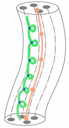
S. Malik / A Sketching Interface for Modeling and Editing Hairstyles

front order similar to the approach described in [KN02].               trolling individual hair strands, which is useful for adding
Interactive frame rates were achieved throughout the                   fine details. The hierarchical cluster model presented by
modeling and editing process using a PC equipped with a                Kim and Neumann [KN02] would help resolve this limita-
Pentium 4 processor running at 3.0 GHz and an ATI                      tion, but it is not immediately clear what sort of interac-
Radeon 9800 video card.                                                tions or gestures could be used to easily traverse the dif-
   While we have not yet performed any detailed usability              ferent detail levels.
study of our interface, we did allow three professional 3D                Hair-hair collision is currently ignored in our system
artists to use the system in order to gauge their feedback.            since the extra processing power it requires would prevent
Each of the artists had experience in character design using           the system from operating in real-time. Nevertheless, it
a number of popular commercial modeling tools, including               would be beneficial to incorporate an efficient hair-hair
basic experience with some existing hair design plugins.               collision algorithm into the current system to further in-
After a brief 5 minute introduction to our hair sketching              crease the realism of the generated hairstyles.
interface, each artist was allowed to freely use the system.              Our cluster generation algorithm currently assumes that
Within 5-10 minutes each artist was creating interesting               the radius remains fixed for the entire generalized cylin-
and detailed styles with relative ease, using about 20-30              der. This reduces the realism of locks or ponytails since
clusters. Figure 18 shows three actual hairstyles created              hair strands do not come together at the tips as expected.
by each of the artists. The artists all commented that the             While the cluster representation presented in [CK05] can
interface was much more intuitive and required                         be used to facilitate such styles, we must still develop the
significantly less time to create detailed styles than the hair        interaction techniques that can provide an intuitive inter-
tools they had used in the past.                                       face to these extra control parameters. One possible solu-
   While overall feedback was positive, one of the artists             tion is to allow clusters to be created by drawing their
felt that the cutting operation wasn’t as precise as he                silhouettes instead of just specifying the internal skeleton
would like it to be when making cutting strokes that were              curve. This would be similar to the extrusion operation
non-orthogonal to the cluster. This is a result of the                 presented in [IMT99] where the generalized cylinder of a
cutting stroke only affecting the underlying control curve             hair cluster could be swept along the outline of a curve
of a hair cluster instead of the actual strands. Regarding             whose endpoints both emanate from locations on the scalp.
the combing operation, one of the artists commented that                  While our user interface currently only allows a user to
in some instances it would be nice if it also took                     rotate the viewpoint around the 3D model, it is reasonably
neighboring cluster directions into account much like the              simple to incorporate translation and zooming to the view-
implanting and lengthening operations, since the current               point control. This would be useful for creating large furry
implementation (which combs in the viewing plane)                      creatures or animals, since our system is general enough to
occassionally leads to strange styles when observed from               allow hair to be placed on any arbitrary 3D model.
different viewpoints. Another minor gripe shared by all
artists was that it was sometimes difficult to implant all of
the initial clusters when creating a new hairstyle from                7. Acknowledgements
scratch. They felt that a simple tool to quickly copy an
                                                                       We would like to thank Allan Jepson, Joe Laszlo, and
existing cluster to other parts of the head would further
                                                                       Abhishek Ranjan for thoughtful discussions. Financial
reduce the time needed to create detailed hairstyles.
                                                                       support by the Natural Science and Engineering Research
                                                                       Council of Canada (NSERC) and the Government of On-
                                                                       tario is gratefully acknowledged.

                                                                       References

                                                                       [CK05] CHOE B., KO H-S.: A Statistical Wisp Model and
                                                                        Pseudophysical Approaches for Interactive Hairstyle
    Figure 18: Three different hairstyles created by first-
                                                                        Generation. In IEEE Transactions on Visualization and
             time users in under 10 minutes.
                                                                        Computer Graphics, 11(2), 2005, pp. 160-170.
6. Conclusions and Future Work                                         [DM93] DALDEGAN A., MAGNENAT-THALMANN N.: Cre-
                                                                        ating Virtual Fur and Hair Styles for Synthetic Actors”.
In this paper we presented interaction techniques and algo-             In Communicating with Virtual Worlds, Springer-Verlag,
rithms for quickly modeling detailed hairstyles using an                1993, pp. 358-370.
intuitive sketching interface. While our tool achieves its
goal of allowing artists to quickly explore a number of                [GSML02] GRABLI S., SILLION F., MARSCHNER S.,
different hairstyles when designing 3D characters, there                LENGYEL J.: Image-based Hair Capture by Inverse Light-
are still areas where the system can be improved. In par-               ing. In Proceedings of Graphics Interface, 2002, pp. 51-
ticular, the use of hair clusters prevents the user from con-           58.

© The Eurographics Association 2005.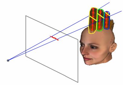
S. Malik / A Sketching Interface for Modeling and Editing Hairstyles

[HM00] HADAP S., MAGNENAT-THALMANN N.: Interac-                        face. In Proceedings of International Conference on
 tive Hair Styler based on Fluid Flow. In Proceedings of               Computer Science (ICCS), 2002. Lecture Notes in Com-
 Eurographics Workshop on Computer Animation, 2000,                    puter Science (LNCS) 2330, pp. 131-140.
 pp. 87-100.
                                                                     [MKIA04] MAO X., KATO H., IMAMIYA A., ANJYO K.:
[HR04] HERNANDEZ B., RUDOMIN I.: Hair Paint. In Pro-                  Sketch Interface Expressive Hairstyle Modeling and
 ceedings of IEEE Computer Graphics International                     Rendering. In Proceedings of IEEE Computer Graphics
 (CGI), 2004. pp. 578-581.                                            International (CGI), 2004, pp. 608-611.
[Hul90] HULTQUIST J.: A Virtual Trackball. Graphics                  [Osh04] OSHITA M.: Pen-to-mime: A Pen-based Interface
 Gems (ed. A. Glassner), Academic Press, 1990, pp. 462-               for Interactive Control of a Human Figure. In Proceed-
 463.                                                                 ings of Eurographics Workshop on Sketch Based Model-
                                                                      ing, 2004, pp. 43-52.
[IH02] IGARASHI T., HUGHES, J. F.: Clothing Manipulation.
  In Proceedings of ACM UIST, 2002, pp. 91-100.                      [PBS04] PARIS S., BRICENO H., SILLION F.: Capture of Hair
                                                                      Geometry from Multiple Images. In ACM Transactions
[IMT99] IGARASHI T., MATSUOKA S., TANAKA H.: Teddy:
                                                                      on Graphics (Proceedings of ACM SIGGRAPH), 2004,
  A Sketching Interface for 3D Freeform Design. In Pro-
                                                                      pp. 712-719.
  ceedings of ACM SIGGRAPH, 1999, pp. 409-416.
                                                                     [RBB04] RAMOS G., BOULOS M., BALAKRISHNAN R.: Pres-
[JS01] JONES M., SATHERLEY R.: Using Distance Fields
                                                                      sure Widgets. In Proceedings of ACM CHI, 2004, pp.
  for Object Representation and Rendering. In Proceed-
                                                                      487-494.
  ings of Eurographics Annual Conference (UK Chapter),
  2001, pp. 37-44.                                                   [TBSR04] TSANG S., BALAKRISHNAN R., SINGH K., RANJAN
                                                                      A.: A Suggestive Interface for Image Guided 3D Sketch-
[KK89] KAJIYA J., KAY T.: Rendering fur with three-
                                                                      ing. In Proceedings of ACM CHI, 2004, pp. 591-598.
 dimensional textures.   In Proceedings of ACM
 SIGGRAPH, 1989, pp. 271-280.                                        [TCH04] TURQUIN E., CANI M-P., HUGHES J. F.: Sketching
                                                                      Garments for Virtual Characters. In Proceedings of Eu-
[KN00] KIM T-Y., NEUMANN U.: A Thin-Shell Volume for
                                                                      rographics Workshop on Sketch Based Modeling, 2004.
 Modeling Human Hair. In Proceedings of IEEE Com-
                                                                      pp. xx-xx.
 puter Animation, 2000, pp. 104-111.
                                                                     [WS92] WATANABE Y., SUENAGA Y.: A Trigonal Prism-
[KN01] KIM T-Y., NEUMANN U.: Opacity Shadow Maps.
                                                                      based Method for Hair Image Generation. In IEEE Com-
 In Proceedings of Eurographics Workshop on Rendering
                                                                      puter Graphics and Applications, Volume 12, Issue 1,
 Techniques, 2001, pp. 177-182.
                                                                      1992, pp. 47-53.
[KN02] KIM T-Y., NEUMANN U.: Interactive Multiresolu-
                                                                     [WOQS05] WEI Y., OFEK E., QUAN L., SHUM H-Y.: Mod-
 tion Hair Modeling and Editing”. In Proceedings of
                                                                      eling Hair from Multiple Views. In ACM Transactions
 ACM SIGGRAPH, 2002, pp. 620-629.
                                                                      on Graphics (Proceedings of ACM SIGGRAPH), 2005.
[LK01] LEE D-W., KO H.: Natural Hairstyle Modeling and                To appear.
 Animation. In Graphical Models, 2001, 63(2), pp. 67-
                                                                     [XY01] XU Z., YANG X-D.: V-HairStudio: An Interactive
 85.
                                                                      Tool for Hair Design. In IEEE Computer Graphics and
[MHK00] MAGNENAT-THALMANN N., HADAP S., KALRA                         Applications. Volume 21, Issue 3, 2001, pp. 36-43.
 P.: State of the Art in Hair Simulation. In Proceedings of
                                                                     [Yu01] YU Y.: Modeling Realistic Virtual Hairstyles. In
 International Workshop on Human Modeling and Anima-
                                                                      Proceedings of Pacific Conference on Computer Graph-
 tion, 2000, Korea Computer Graphics Society, pp. 3-9.
                                                                      ics and Applications (PG), 2001, pp. 295-304.
[MKKI02] MAO X., KASHIO K., KATO H., IMAMIYA A.:
 Interactive Hairstyling Modeling using a Sketching Inter-

                                                                                                 © The Eurographics Association 2005.
You can also read