A Users Guide for the CFI Calculator and Fire Dynamics Equations - A publication by: The International Association of Arson Investigators and The ...
←
→
Page content transcription
If your browser does not render page correctly, please read the page content below
A Users Guide for the CFI Calculator
   and Fire Dynamics Equations

                   A publication by:

  The International Association of Arson Investigators
                          and
       The CFITrainer.net Steering Committee

                       Prepared by:

                      Robert J. Schaal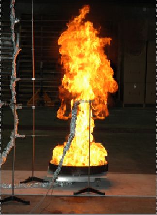
Disclaimer

The International Association of Arson Investigators (IAAI), CFITrainer.net and
Stonehouse Media make no warranty, expressed or implied, to users of the CFI
Calculator and the CFI Calculator Users Guide and accepts no responsibility for its use.
Users of CFI Calculator and the CFI Calculator Users Guide assume sole responsibility
for determining the appropriateness of its use in any particular application; for any
conclusions drawn from the results of its use; and for any actions taken or not taken as a
result of analysis performed using this tool.

Users are warned that CFI Calculator and the CFI Calculator Users Guide is intended for
use only by those competent in the field heat transfer, combustion and fire science, and is
intended only to supplement the informed judgment of the qualified user. This calculator
may or may not have predictive capability when applied to a specific set of factual
circumstances. All results should be evaluated by an informed user.

This document has undergone extensive review but no warranty against errors or
omissions is expressed or implied.

The IAAI would like to thank the following individuals for their review and contributions
to this document:

Special Agent Robert J. Schaal, ATF – Principal Writer
Dr. James Quintiere – Technical Review and Editing
Special Agent Daniel Heenan, ATF – Technical Review and Editing
Special Agent Steven Avato, ATF – Technical Review and Editing
Special Agent Steven Carman, ATF – Technical Review and Editing
Liz Connolly, Stonehouse Media – Project Development and Coordination
Ian Scott, Stonehouse Media- Developer
Jason Jammer, Stonehouse Media- Art Director
Jon Jones, Jones and Associates – Project Development and Coordination

                                                                                             2
Copyright www.CFITrainer.net, 2005-2008.
Table of Contents

Introduction……………………………………………Page 4

Downloading…………………………………………..Page 5

User Interface………………………………………….Page 6

Equations………………………………………………Page 7

Heat Release Rate……………………………………..Page 8

Flame Height………………………………………....Page 14

Heat Flux……………………………………………..Page 25

Time to Ignition………………………………………Page 33

Flashover……………………………………………...Page 37

Fire Growth…………………………………………...Page 48

Sprinkler Activation………………………………….Page 53

End Notes ……………………………………………Page 59

                                                 3
Copyright www.CFITrainer.net, 2005-2008.
INTRODUCTION:

       The CFITrainer.net CFI Calculator was developed as a part of a grant received by

the International Association of Arson Investigators through the Federal Emergency

Management Agency, Assistance to Firefighters Grant Program. The calculator is

designed to assist field fire investigators in the development and testing of hypothesis

while utilizing the scientific method, and to provide the investigator a tool that can be

utilized to analyze fire behavior using fire dynamics equations.

        The various formulae contained in the CFI calculator tool were derived from

existing scientific publications and literature and have been subjected to continued

assessment and peer review. The calculator is currently published in three formats,

including a Palm OS application, a Pocket PC application and a desktop PC application.

         While the look and feel of the three versions may differ slightly as a result of

operating systems functionality and screen real estate issues, the calculated results are

consistent. The tool has undergone extensive testing to ensure that the calculated results

are consistent with calculated results derived utilizing alternative methods including long

hand equation solving, solving utilizing programmable scientific calculators and solving

utilizing other computer based tools.

       The calculator currently contains seven equations including Flame Height, Heat

Flux, Flashover, Fire Growth, Sprinkler Activation, Heat Release Rate and Time to

Ignition. A number of these equations contain radio buttons, which are utilized to

increase the functionality of the equation, allowing the user to solve for different

unknown variables. Additionally, the tool employs drop down menus in a number of

equations to serve as a reference guide for commonly utilized values.

                                                                                             4
Copyright www.CFITrainer.net, 2005-2008.
While the equations stand alone in analyzing specific aspects of fire growth and

behavior, there is an interrelationship between a number of the equations such as Heat

Release Rate and Flame Height or Heat Release Rate and Heat Flux, etc.. This allows the

equations to be utilized in conjunction with one another to analyze multiple aspects of a

given scenario. While these equations can be very useful in hypothesis development and

testing, it is important to recognize that these formulas do have limitations and are

appropriately utilized to bound a problem, defining a “fence” around the realm of

possibilities. These equations may provide support to a hypothesis or show that a

particular hypothesis is less likely than others. However, no single formula or data will

typically prove that an event could not have occurred; only that is was less likely given

the parameters. For example, in estimating a time to Flashover the investigator may

calculate a range of values from 1 to 4 minutes (depending on input). This should not be

taken as proof that Flashover could not have occurred at 5 minutes, only that Flashover

was feasible as soon as 1 to 4 minutes. This tool is designed to be utilized by those

individuals that have a sound knowledge of fire dynamics and fire dynamics equations

and the use of this tool may require referencing additional scientific literature or

consulting outside experts.

DOWNLOADING:

       The CFI Calculator is available for download to registered CFITrainer.net users at

www.cfitrainer.net. All three versions (Palm, Pocket PC and Desktop) are available on

this website and users are free to choose any or all of the applications. The desktop and

Pocket PC versions require the installation of a .Net Framework version 2.0 application

and directions for locating the download are available on the CFITrainer.net site.

                                                                                            5
Copyright www.CFITrainer.net, 2005-2008.
Installation of updated versions may require the removal of older versions. Technical

support is available if users have problems installing or running the applications.

Additionally, the site hosts a frequently asked questions forum that addresses many of the

common questions a user may have without the need for additional technical support.

Users are also encouraged to provide feedback to the development team to ensure that the

product is serving the needs of the fire investigation community, identify potential bugs

that need correction, and provide insight on how the tool should be improved in future

releases.

USER INTERFACE:

       The application is typically launched by pressing a screen icon, similar to other

computer applications. Upon opening, the home screen will appear, listing the various

equations contained in the calculator tool. The equations are listed on “buttons” that are

utilized to launch each specific equation tool. Additionally, a link to the general

disclaimer is available on the home screen, warning users of the limitations of the tool.

Once a button is clicked, the selected calculation will open and an input screen will

appear allowing the input of the required variables necessary for solving the particular

equation. The screen also includes a help button that opens additional information

concerning the application of a particular formula and contains limited reference material.

Additional navigation tools are available including a “Home” button that takes the user

back to the opening screen containing all of the equations and a calculate button that will

solve the equation and take the user to the output screen. The Pocket PC and Desktop

version also contain a numeric and/or graphic input tool, which can be utilized for

inputting the necessary data without the use of an external keyboard. As previously

                                                                                             6
Copyright www.CFITrainer.net, 2005-2008.
mentioned, a number of applications contain drop down menus, allowing the input of
common values without the need of additional reference materials. In a number of
applications, these drop down menus can be toggled on and off by depressing a button,
allowing the user to manually input specific data, if available. Once transitioning to the
output screen, the user will view the calculated results and additionally have a “Back”
button navigation tool that returns the program to the input screen of the specific
equation, allowing the user to run multiple iterations of the equation without difficulty.
The program does not store or recall results so it is imperative that the user record the
input variables and the output measures for later use.
EQUATIONS:
The next several sections relate to the various equations included in the CFI
Calculator tool and are designed to break each formula down so the user understands
what the requested input means, where to find the input data, and what the output
measurements signify. By providing the user a better fundamental understanding of the
equations, it is believed that the user will become better informed and better able to apply
the tool to their fire scene hypotheses. The formulas and the CFI Calculator tool are
designed to assist the field investigator in the analysis of fire behavior at fire event,
analyze witness statements versus expected fire behavior, and predict results when
conducting tests and experimentation. The formulas and the CFI Calculator tool are
intended to be utilized as a part of and in furtherance of the proper application of the
Scientific Method to a fire scene investigation. As some applications utilize more than
one formula in calculating output data, each formula utilized will be discussed in the
appropriate section to which it relates. The equations will not necessarily be discussed in
7
Copyright www.CFITrainer.net, 2005-2008.the order in which they appear on the CFI Calculator tool. It is important to note that
all equations require input in metric values and conversions should be done prior to
utilizing this tool.
The most common measurements that need to be converted are feet to meters and
o
Fahrenheit to oCelsius. Simple formulas for these conversions are:
meters = feet / 3.2808 and °Celsius = (° Fahrenheit − 32) / 1.8
HEAT RELEASE RATE:
One of the fundamental properties of a fuel is its Heat Release Rate or Fire Power,
which represents how much energy an item gives off over a period of time. It is
represented by the symbol Q& , and is most accurately defined as “the energy produced by
the fire per unit time or fire power.”1 It takes into account a fuel’s effective heat of
combustion (energy released by the fire per unit mass of burned fuels)2, the mass loss rate
per unit area (the mass of the fuel vaporized but not necessarily burned)3, and the burning
area.
The formula for determining the heat release rate or energy release rate4 of a give fuel is:
Q& = m& ′′A ΔH c
Where:
Q& = Heat Release Rate in Kilowatts (kW)
m& ′′ = Mass Loss Rate of a given fuel in grams per unit area per second
( g m 2 − s ). This value relates to how much “weight” a fuel loses over a given
time (in seconds) and is usually a value derived from scientific reference material.
8
Copyright www.CFITrainer.net, 2005-2008.A = the area involved in the vaporization measured in square meters. (Note:
π
When calculating the area of a pool fire, utilize the equation A = D 2 , where D =
4
the diameter of the pool.)
ΔH c = the effective heat of combustion measured in kilojoules per g ( kJ g ).
This value is usually derived from scientific reference material.
Utilizing this equation to calculate the estimated heat release rate of a pool fire of
gasoline measuring approximately 1 meter across, with a Heat of Combustion ( Δ Hc )
value of 43.7 kJ g and a Mass Loss Rate ( m& ′′ ) value of 55 g m 2 − s (Average of range -
50-60 g m 2 − s ), the area of the fuel would first be calculated as follows:
π π
A= D2 = (1 m) 2 = 0.785 m 2
4 4
The Heat Release Rate equation would then be utilized by inserting the data in the
appropriate fields and the following results would be expected:
Q& = (55 g / m2 − s)(0.785 m2 ) (43.7 kJ / g )
Q& = 1887 kW
The expected input screen and output screen utilizing the CFI Calculator tool with
the same values discussed previously are demonstrated below:
9
Copyright www.CFITrainer.net, 2005-2008.The tool is designed to allow the user to utilize the materials drop down menu (in
this example we would select gasoline, and the stored data for the mass loss rate and
effective heat of combustion would be utilized in the calculation. References for the
values utilized in the drop down menu are also contained in the help file) or exact
variables can be entered, if known to the user. When determining the area involved in
vaporization, it is calculated by multiplying the length in meters by the width in meters.
The area of a pool fire is calculated based on it’s diameter in meters. For irregular shaped
objects or irregular shaped pools, some approximations or estimates might have to be
utilized. This calculator application has a radio button that allows the user to select if
they are calculating the Heat Release Rate of a pool or a standard item. Examples of the
drop down menu and reference help file are illustrated below:
10
Copyright www.CFITrainer.net, 2005-2008.An additional check with an Excel Spreadsheet tool (based on a spreadsheet tool
developed by Dr. Fred Mowrer5, with minor modifications) would yield the following
output results:
Q dot = Heat Release Rate
Input Parameters
Heat of Combustion (ΔHc) 43.7 kJs/m2
Mass Loss ( m& ′′ ) 55 kgs/m2
Area of Fuel Surface (A) 0.785 m2
Calculated Parameters
Heat Release Rate ( Q& ) 1886.7 kW
These examples demonstrate that the calculated results are consistent with the
manual calculation, the CFI Calculator Tool and the Excel Spreadsheet. Additional
validation can be done by comparing the calculated/estimated results with data derived as
a result of laboratory experimentation.
11
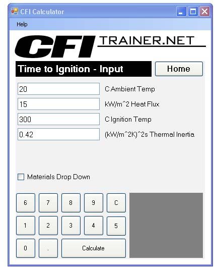
Copyright www.CFITrainer.net, 2005-2008.In 2005, an experiment involving a gasoline pool fire was conducted at the
Bureau of Alcohol, Tobacco, Firearms and Explosives, Fire Research Laboratory as a
part of a training session conducted for the International Association of Arson
Investigators 56th Annual Training Conference. The experiment involved burning
approximately 3.79 liters (1 gallon) of gasoline in a pan measuring approximately 0.55
meters (22 inches) in diameter. The pan was placed on a load cell to calculate the mass
loss rate and the burn was conducted under a cone calorimeter to allow for the
measurement of both peak heat release rate and total heat release rate. Thermocouples
were set above the pool in 0.30 meter (1 foot) increments and heat flux gauges were set
up approximately 0.50 meters and 1 meter from the axis of the pan.
With the given parameters of the experiment, the fuel properties and pan
dimension can be utilized to calculate the estimated heat release rate. With the given
values, the calculated peak heat release rate would yield the following results:
Area of Pool:
π π π
A= D2 = (0.55 m) 2 = (.303 m 2 ) = 0.238 m 2
4 4 4
Heat Release Rate:
Q& = (55 g / m 2 − s)(0.238m 2 ) (43.7 kJ / g )
Q& = 572 kW
12
Copyright www.CFITrainer.net, 2005-2008.The estimated peak heat release rate of the fire defined in these experiments is
572 kW. The experiment was run two times under the same set up parameters with the
results listed below:
Peak 30 second 1 minute 5 minute Total heat
(kW) maximum maximum maximum released (kJ)
average (kW) average (kW) average (kW)
326 306 299 266 94607
491 457 442 309 96949
As is demonstrated in this experiment, the measured results of actual peak heat
release rate in the two experiments (326 kW and 491 kW respectively) utilizing the same
parameters, fall below the calculated results of 572 kW. Utilizing the range of mass loss
rate published for gasoline (50-60 g m 2 − s ) the peak heat release rate can be calculated
at somewhere between 518 kW and 622 kW for the parameters defined in the experiment.
These results are closer to the observed measurements at the lower end, and certainly
help illustrate that these equations are appropriately utilized to bound a problem but
cannot be expected to yield exact results. The number of variables that can influence
experimental results including heat loss to the pan and heat loss to the floor are often too
difficult to factor into equations and, therefore, experimentally derived results will vary
not only from test to test but, often from the calculated results as well. These differences
not withstanding, utilized appropriately, fire dynamics equations and calculations can
serve an important role in the analysis of fire events.
The Heat Release Rate measurement is a common input value throughout most of
the equations utilized in the CFI Calculator tool. In particular, it is closely associated
with the flame height and heat flux calculations, as these properties are a function of, or
13
Copyright www.CFITrainer.net, 2005-2008.greatly influenced by Heat Release Rate. While the Heat Release Rate equation can be
utilized on it’s own to help quantify the amount of energy a particular fuel or item will
release, these other equations can also be utilized to help the investigator estimate this
property of a burning item. The alternative uses of additional formulas will be discussed
in the appropriate section.
FLAME HEIGHT
Flame height is closely associated with the amount of energy being released by a
fuel (Heat Release Rate or Q& ) with fuels with higher energy release rates expected to
have higher flame heights as compared to those with lower heat release rates. Other
factors, such as fuel configuration and fuel location, can also influence flame height and
should be considered when utilizing these formulae. There are a number of calculations
that have been developed that can be utilized to estimate the flame height based on the
heat release rate and conversely, estimate the heat release rate based on an observed
flame height. These formulas are useful in predictive analysis while conducting fire
testing as well as analyzing witness statements. When calculating flame height, the
measurement is taken from the base of the flame to the height above the flaming object,
not from the base of the object.
14
Copyright www.CFITrainer.net, 2005-2008.Flame Height Calculations
Flame height measured
from base of flame
lf lf
lf
The first formula to be discussed was developed by McCaffrey6 and is expressed
as follows:
Z c = 0.08 Q& 2 / 5 and Z i = 0.20 Q& 2 / 5
Where:
Z c
= Consistent Height of Flame in Meters
Z i
= Intermittent Height of Flame in Meters
0.08 = Consistent Flame Variable in m/kW
0.20 = Intermittent Flame Variable in m/kW
Q& = Heat Release Rate of Fire in Kilowatts
In this equation, McCaffrey utilizes the variables of 0.08 and 0.20 for the
consistent flame height and intermittent flame height respectively. This formula
describes the flame as varying between a relatively consistent height (the 0.08 value) and
an intermittent, but higher level (0.20 value) that the flame reaches as it undulates or
15
Copyright www.CFITrainer.net, 2005-2008.flickers at a periodic rate. These additional variables allow for additional estimations or
calculations utilizing this methodology.
An example of the use of this formula calculating the consistent flame height of a
500 kW is as follows:
Z c = 0.08 m / kW (500 kW ) 2 / 5
Z c = 0.08 m / kW (12 kW )
Z c = 0.96 m
The same example of this formula calculating the intermittent flame height would
yield the following results:
Z i = 0.20 m / kW (500 kW ) 2 / 5
Z i = 0.20 m / kW (12 kW )
Zi = 2.4 m
While McCaffrey’s calculation does provide for estimating the consistent flame
height and the intermittent flame height, the CFI Calculator utilizes the intermittent
variable (0.20) as the observed results are more consistent with the methods of Heskestad
and Alpert and Ward that incorporate an “average” variable, and compares more
favorably to experimental data that will be discussed later.
These same input variables can be utilized to calculate the Heat Release Rate ( Q& )
of a fire where the flame height is know either through actual measurement or estimated
16
Copyright www.CFITrainer.net, 2005-2008.from observation. The equation can be rebalanced algebraically to solve for the
unknown, in this case Q& , as follows:
Z i = 0.20 (Q& ) 2 / 5
Divide each side by (0.20):
⎧ Z i 0.20 (Q& ) 2 / 5 ⎫ ⎧ Zi ⎫
⎨ = ⎬ = ⎨ = (Q& ) 2 / 5 ⎬
⎩ 0 . 20 0.20 ⎭ ⎩ 0.20 ⎭
Raise each side to a power of (5/2):
⎧ Zi 5/ 2 ⎫ ⎧ ⎫
⎨( ) = ((Q& ) 2 / 5 )5 / 2 ⎬ = ⎨( Z i )5 / 2 = Q& ⎬
⎩ 0.20 ⎭ ⎩ 0.20 ⎭
Utilizing the results of 2.4 meters, we obtained from calculating the flame height
of a fire with a Heat Release Rate of 500 kW, we would estimate the heat release rate as
follows:
2.4 m
( )5 / 2 = Q&
0.20 m / kW
(12 kW )5 / 2 = Q&
498 kW = Q&
This result compares favorably to the 500 kW fire in the example, with the
differences attributed to the rounding properties assigned to the calculator.
A second method of calculating flame height was developed by Heskestad7,8,9.
This formula is typically utilized for calculating the flame height of pool fire and
included a flame diameter variable. This formula compares well to the other formulas
17
Copyright www.CFITrainer.net, 2005-2008.and can be used to calculate the flame height of other burning objects, in addition to pool
fires. It is expressed as follows:
L f = 0.23 Q& 2 / 5 − 1.02 D
Where:
L f
= Height of Flame in Meters
Q& = Heat Release Rate of Fire in Kilowatts
D = Diameter of Flame in Meters
0.23 = Flame constant expressed in m/kW
Utilizing the same example of a 500 kW fire that was discussed in the McCaffrey
example and defining the diameter at 0.50 meters, the following results would be
expected:
L f = 0.23 m / kW (500 kW ) 2 / 5 − 1.02 (0.50 m)
L f = 0.23 m / kW (12 kW )− (.51m)
L f = (2.76 m)− (.51m)
L f = 2.25 m
This result compares favorably to the McCaffrey Intermittent results of 2.4
meters. Again, this formula can be reconfigured algebraically to solve for the heat
release rate as follows:
L f = 0.23 Q& 2 / 5 − 1.02 D
18
Copyright www.CFITrainer.net, 2005-2008.Add (1.02D) to each side:
{L + 1.02D = (0.23 Q&
f
2/5
} { L + 1.02D = 0.23Q& }
− 1.02 D) + 1.02 D =
f
2/5
Divide each side by (0.23):
⎧⎪ L f + 1.02 D 0.23 Q& 2 / 5 ⎫⎪ ⎧⎪ L f + 1.02 D ⎫⎪
⎨( )= ⎬ = ⎨( ) = Q& 2 / 5 ⎬
⎪⎩ 0.23 0.23 ⎪⎭ ⎪⎩ 0.23 ⎪⎭
Raise each side to the power of (5/2):
⎧⎪ L f + 1.02 D 5 / 2 ⎫
2/5 5/ 2 ⎪ ⎧⎪ L f + 1.02 D 5 / 2 ⎫⎪
⎨ = & ⎬ = ⎨ = &
( ) (Q ) ( ) Q ⎬
⎪⎩ 0.23 ⎪⎭ ⎪⎩ 0.23 ⎪⎭
Utilizing the example of a 2.25-meter flame height, (calculated from a given heat
release rate of 500 kW) and a flame diameter of 0.50 meters, the results for an estimated
heat release rate would be as follows:
(2.25 m) + 1.02(0.50 m) 5 / 2 &
( ) =Q
0.23
(2.25 m) + (.51 m) 5 / 2 &
( ) =Q
0.23 m / kW
2.76 m 5 / 2 &
( ) =Q
0.23 m / kW
(12 kW ) 5 / 2 = Q&
498 kW = Q&
19
Copyright www.CFITrainer.net, 2005-2008.Again, this result compares favorably with what the expected results of 500 kW
and the minor differences can be attributed to rounding.
The third formula included in the CFI Calculator and discussed in this paper, was
developed by Alpert and Ward10 and is included in the 2004 edition of NFPA 92111.
Similar to the other equations discussed, this calculation is based predominately on the
heat release rate. This equation includes a location factor, which is utilized to estimate
the effects of entrainment on the flame height. Recent experimentation has indicated that
the limiting effects of entrainment (factored at 50% for a wall configuration and 75% for
a corner configuration) may not be as great as previously reported. Fuel shape does have
some influence on this limiting effect, for example a square fuel against a wall or corner
will reduce entrainment more than a round fuel in against a wall or corner. While the use
of an entrainment-limiting factor is somewhat subjective, they can be utilized to establish
a range of flame heights for use in scene analysis. The equation is expressed as follows:
H f = 0.174 (k Q& ) 2 / 5
Where:
H f
= Height of Flames in Meters
k = Location of Fire in Compartment with:
1= Center of Room
2= Against Wall
4= Corner of Room
Q& = Heat Release Rate of Fire in Kilowatts
0.174 = Flame Constant in m/kW
20
Copyright www.CFITrainer.net, 2005-2008.Utilizing the same example of a 500 kW fire that was discussed in the other two
equations, and giving it a center of the room value of (1) the following results would be
expected:
Hf = 0.174 m/ kW ((1) (500kW)) 2/5
H f = 0.174 m / kW (500 kW ) 2 / 5
H f = 0.174 m / kW (12 kW )
H f = 2.09 m
This result also compares favorably with the result obtained from the McCaffrey
equation (2.4 meters) and the Heskestad equation (2.25 meters). The differences again,
demonstrate that these formulas do have limitations and are appropriately utilized to
bound a problem, defining a reasonable range of possibilities versus what scientifically
could not happen.
Like the other flame height calculations, the Alpert and Ward formula can be
reconfigured algebraically to solve for the heat release rate based on a known flame
height. The formula would be configured as follows:
H f = 0.174 (k Q& ) 2 / 5
Divide each side by (0.174):
⎧
⎨H f 0.174 =
⎩
0.174(k Q& ) 2 / 5 ⎫
0.174
⎬
⎭
= {H f 0.174 = (k Q& ) 2 / 5 }
21
Copyright www.CFITrainer.net, 2005-2008.Raise each side to the power of (5/2):
{(H f 0.174)5 / 2 = ( (k Q& ) 2 / 5 )5 / 2 } = {( H f }
0.174) 5 / 2 = (k Q& )
Divide each side by (k):
⎧⎪ ( H f 0.174)5 / 2 (k Q& ) ⎫⎪ ⎧⎪ ( H f 0.174) 5 / 2 ⎫⎪
⎨ = ⎬ ⎨ &
= Q⎬
⎪⎩ k k ⎪⎭ = ⎪⎩ k ⎪⎭
Utilizing the example of a 2.09 meter flame height, (calculated from a given heat
release rate of 500 kW) and a center of the room location factor of (1), the results for an
estimated heat release rate would be as follows:
(2.09 m 0.174 m / kW 5 / 2 &
=Q
1
(12 kW )5 / 2 = Q&
1
498 kW &
=Q
1
498 kW = Q&
These results are consistent with the heat release rate results utilizing the other
flame height calculations are consistent with our expected output of 500 kW. Again, the
minor difference can be attributed to rounding issues.
A comparison of the calculated results with the Excel spreadsheet tool indicates
very consistent results.
22
Copyright www.CFITrainer.net, 2005-2008.Estimate of Flame Heights Calculated
Input Parameters
Heat Release Rate 500 kW
Wall Factor (kLF) 1
Diameter (Pool Fires)(D) 0.5 m
Calculated Parameters
Persistent Flame Height 1.0 m
Intermittent Flame Height 2.4 m 2.4
NFPA Flame Height 2.1 m 2.09
Pool Fire Flame Height 2.3 m 2.25
When utilizing the CFI Calculator tool, selecting the Flame Height button from
the initial user interface will open the input screen. From the input screen, the user can
toggle to calculate flame height based on heat release rate or heat release rate based on
flame height as we have previously discussed. Samples of the input screen with the
values utilized in earlier examples and the output screen revealing the calculated results
are demonstrated below. These values are, again, consistent with the other tools utilized
to make these calculations including hand calculating and the Excel spreadsheet.
23
Copyright www.CFITrainer.net, 2005-2008.For an example of the practical application of the flame height calculation, the
2005 experiment at the Fire Research Laboratory can be utilized. Recall that the
experiment involved burning approximately 3.79 liters (1 gallon) of gasoline in a pan
measuring approximately 0.55 meters (22 inches) in diameter. The pan was placed on a
load cell to calculate the mass loss rate and additionally the burn was conducted under a
cone calorimeter to allow for the measurement of the peak heat release rate and total heat
release rate. Thermocouples were set above the pool in 0.30 meter (1 foot) increments
and heat flux gauges were set up approximately 0.50 meters and 1 meter from the axis of
the pan. The calculated heat release rate with the given parameters was 572 kW and the
measured results from the two experiments were 326 kW and 491 kW respectively.
Utilizing these figures in the flame height equations, the calculated flame height would be
as follows:
Alpert and
Method HRR McCaffrey Heskestad Ward
Calculated 572 kW 2.54 m 2.35 m 2.21 m
Exp 1 326 kW 2.02 m 1.77 m 1.76 m
Exp 2 491 kW 2.38 m 2.18 m 2.07 m
Observational evidence derived from photographs indicates a flame height in the
range of 1.8 meters (6 feet) above the pool. This compares most closely to the calculated
results of experiment 1. In comparing the observed results to the range of calculated
results, there are some differences noted, however they are fairly accurate for this type of
application. Again, we are establishing a range of possibilities versus developing an
exact result.
24
Copyright www.CFITrainer.net, 2005-2008.If we utilize the observed flame height of 1.8 meters to calculate an estimated heat
release rate we would observe the following:
HRR Calculation
Calculate the Estimated Heat
Release Rate Given Estimated 5’
Flame Height of 6’ (1.8m)
4’
McCaffrey = 252 kW
Alpert and Ward= 358 kW 3’
Heskestad = 351 kW
2’
Actual HRR Exp 1= 326 kW
Actual HRR Exp 2= 491 kW 1’
Again, minor differences are observed, but it is clear that the calculated results are
reasonably reliable and are within the “fence of reality” established by the measured
results. These results help indicate that the calculations can be reliable within the scope of
their intended use and can be effectively utilized in analytical analysis.
HEAT FLUX
The heat flux equation utilized in the CFI Calculator measures the radiant heat
flux utilizing a point-source method. This methodology is based on the assumption that
all of the energy is received uniformly a sphere radius from the flame.12 The tool is set up
similar to the flame height calculation, in that the formula can be utilized to calculate heat
flux based on a known heat release rate (calculated utilizing the heat release rate equation
or the flame height equation or obtained from published literature) or utilized to calculate
the heat release rate if a heat flux value is known. Radiation is heat energy that is
transferred through electromagnetic waves and unlike conduction and convection, this
25
Copyright www.CFITrainer.net, 2005-2008.form of energy transfer does not need any intervening medium. Heat flux can be defined
as the heat flow per unit area of flow path13 and is generally expressed in kilowatts per
meter squared (kW/m2). As a fire transitions through the development stages, radiation
becomes the dominant form of energy transfer and greatly influences fire progression as
it preheats and ignites additional fuels. The heat flux equation is based on a number of
factors including the heat release rate, how efficiently the fuel radiates energy (radiation
fraction) and the distance between the fuel and the target. The equation is stated as
follows:
X r Q&
q& =
"
4πc 2
Where:
q& ′′ = Heat Flux in kilowatts per meter squared ( kW )
m2
X r = Fraction (percentage of Combustion Energy lost by the flame as Radiation
(Value generally acquired from reference material)
Q& = Rate of Heat Release measured in kilowatts. (usually estimated based on
published reference material or calculated utilizing other formulas such as Heat
Release Rate or Flame Height (in Heat Release Rate mode)
c =distance between the axis of the flame and the target receiving the radiation in
meters.
The Radiation Fraction ( X r ) factor relates to how efficiently a given fuel radiates
energy and is expressed as a fraction of energy radiated relative to the total energy
released. It is not a constant for a given fuel but will vary between 0.15 for low soot fuels
such as methane to 0.60 for high soot fuels such as polystyrene.14 This value can
26
Copyright www.CFITrainer.net, 2005-2008.generally be estimated based on values in published literature, and the CFI Calculator
includes a drop down menu with the values of methane, wood, and gasoline being:
GAS=0.45 (Average Radiation Fraction for Gasoline)
WOOD=0.35 (Average Radiation Fraction for Wood)
METH=0.17 (Average Radiation Fraction for Methanol and methane)
It is advisable to run multiple iterations of the equation utilizing the range of values so a
more accurate and useful estimation can be made. It should also be note that as the
diameter of a fire increases the Radiation Fraction ( X r ) decreases.
The equation is generally accurate when applied to a target that is more than two
flame diameters from the axis of the flame. The potential for ignition caused by radiation
for thermally thin materials increases at 10 kW/m2 and above and at 20 kW/m2 for
thermally thick materials.15 Floor-level heat flux at the onset of flashover is typically
measured in excess of 20-25 kW/m2 and this can typically be achieved when the upper
smoke layer temperature reaches the 500 o -600 o Celsius range.16
Measure Flux from Axis of
Flame
Flame Axis
q”
Source Target
27
Copyright www.CFITrainer.net, 2005-2008.A typical application of the formula to estimate the heat flux received by an object
1 meter away from the flame axis, utilizing a heat release rate of 500 kW, the radiation
fraction of wood (0.35) would appear as follows:
(0.35) (500 kW )
q& " =
4π (1m) 2
175 kW
q& " =
12.56 m 2
q& " = 13.9 kW m 2
It is important to note that the heat flux formula follows the inverse square rule,
meaning that the flux is inversely proportional to the square of the distance between the
flame and the target. This means that doubling the distance between the flame and the
target (for example from 1 meter to 2 meters) reduces the flux by 75%, not simply 50%
that one might think. An example utilizing the 2-meter value would appear as follows:
(0.35) (500 kW )
q& " =
4π (2 m) 2
175 kW
q& " =
4π (4 m2 )
175 kW
q& " =
50.24m2
28
Copyright www.CFITrainer.net, 2005-2008.q& " = 3.48 kW m 2
Comparing the results of the two calculations, it is observed that the value of 3.48
kW/m2 measured at 2 meters away is approximately 75% of the value of 13.93 kW/m2
measured at 1 meter away.
As indicated earlier, this equation can be rearranged algebraically to solve for heat
release rate if the heat flux is known (or given if estimating what the heat release rate
would need to be to yield a flux value at a given distance). The formula is rearranges as
follows:
X r Q&
q& =
"
4πc 2
Multiply each side by 4π c 2 :
⎧ ⎛ X r Q& ⎞ ⎫
′
′
⎨q& 4πc = ⎜
2
⎜ ⎟
2 ⎟
4πc ⎬ {q& ′′4πc 2 = X Q& }
2
⎩ ⎝ 4πc ⎠ ⎭
= r
Divide each side by X r :
⎧ q& ′′4πc 2 X r Q& ⎫ ⎧ q& ′′4πc 2 & ⎫
⎨ = ⎬=⎨ = Q⎬
⎩ Xr Xr ⎭ ⎩ Xr ⎭
Utilizing the results of 13.93 kW/m2, we obtained from calculating the heat flux 1
meter away from a wood fire with a radiation fraction of 0.35 a fire, we would estimate
the heat release rate as follows:
29
Copyright www.CFITrainer.net, 2005-2008.(13.93kW / m 2 )(4π (1m) 2 ) &
=Q
0.35
(13.93kW / m 2 )(12.56 m 2 )) &
=Q
0.35
174.96 kW
= Q&
0.35
499.98 kW = Q&
This value compares favorably to the heat release rate of 500 kW utilized in the
original examples, with the minor differences attributed to rounding.
When utilizing the CFI Calculator tool, selecting the Heat Flux button from the
initial user interface will open the input screen. From the input screen, the user can
toggle to calculate heat flux based on heat release rate or heat release rate based on heat
flux as we have previously discussed. Samples of the input screen with the values
utilized in earlier examples and the output screen revealing the calculated results are
demonstrated below.
30
Copyright www.CFITrainer.net, 2005-2008.The 2005 Fire Research Laboratory experiment can again, be utilized as an
example of the practical application of the heat flux calculation. Recall that the
experiment involved burning approximately 3.79 liters (1 gallon) of gasoline in a pan
measuring approximately 0.55 meters (22 inches) in diameter and heat flux gauges were
31
Copyright www.CFITrainer.net, 2005-2008.placed 0.50 meters and 1 meter from the axis of the pan. The pan was placed on a load
cell to calculate the mass loss rate and additionally the burn was conducted under a cone
calorimeter to allow for the measurement of the peak heat release rate and total heat
release rate. The calculated heat release rate with the given parameters was 572 kW and
the measured results from the two experiments were 326 kW and 491 kW respectively.
Utilizing these figures in the heat flux equation, the heat flux would be calculated with
the following results:
Heat Flux Calculations
Calculate the Heat Flux at .5 meter and 1
meter Given the Estimated Heat Release
Rates based on Flame Height
Method HRR .5 meter 1 meter
McCaffrey 252 36 9
NFPA 358 50 12
Heskestad 351 51 12
Actual (calc 1) 326 46 11
Actual (calc 2) 491 78 19.5
Actual (Exp 1) 326 27 9.7
Actual (Exp 2) 491 29.2 11.5
From the above results, it is observed that the 1-meter values are consistent and
compare favorably to the actual measured values. The 0.50 results do not show as much
accuracy and this can be attributed to the fact that the calculated results and measured
results are less than a flame diameter away from the flame axis. The equation can be
effectively utilized with the values derived from other equations, such as Heat Release
32
Copyright www.CFITrainer.net, 2005-2008.Rate or Flame Height (Heat Release Rate Option). Used within its limits, the equation
can be utilized effectively to assist in fire progression and analyzing witness statements.
TIME TO IGNITION:
The Time to Ignition formula has a close inter-relationship to the heat flux values.
The Time to Ignition formula17 is useful in analyzing fire progression and determining
how long a secondary fuel would take to ignite (progress from one fuel to another).
There is a differentiation between calculating ignition times of thin fuels (thermally thin)
and thick fuels (thermally thick). The calculator only utilizes the methodology for
calculating ignition of thermally thick fuels and this will be the only process discussed.
The formula utilizes certain properties of the fuel including the ignition temperature and
the thermal inertia ( kρ c ), as well as the heat flux being applied to the fuels and the
ambient temperature in the environment. The thermal inertia is defined as “a thermal
property responsible for temperature rise.”18 More simply, thermal inertia is a property
related to how easy or difficult a fuel it is to get a fuel involved in the fire process. Fuels
with low thermal inertia are more readily ignited, while fuels with high thermal inertia
are more difficult to ignite. The formula is expressed at follows:
⎡ Tig − Ts ⎤
2
π
t ig = 4 κρc ⎢⎣ q& ′′ ⎥⎦
Where:
t ig = Time to ignition in seconds
33
Copyright www.CFITrainer.net, 2005-2008.kρ c = Thermal inertia of fuel (typically obtained from appropriate reference
(kW / m 2 K ) 2
material) measured in (where k = thermal conductivity, ρ = density
s
and c = specific heat capacity)
Tig = Auto Ignition temperature of fuel item in degrees Celsius (typically
obtained from appropriate reference material)
Ts = Ambient temperature of compartment in degrees Celsius
q& ′′ = Heat flux being applied to fuel in kW/m2 (can be estimated or calculated
using other methods as heat flux formula)
Utilizing the reference values for ¾-inch plywood (19mm) of a thermal inertia
0.54 and an ignition temperature of 390 o Celsius, along with a measured ambient
temperature of 29 o Celsius and heat flux of 20 kW/m2, the equation would be worked as
follows:
2
π (kW / m 2 K ) 2 ⎡ 390 s − 29 s ⎤
t ig = 4 (0.54 s
)⎢
⎣ 20 kW / m ⎦
2 ⎥
2
( kW m 2 K ) 2 ⎡ 361 s ⎤
t ig = (.785)(0.54 s
)⎢ 2 ⎥
⎣ 20 kW / m ⎦
2
( kW / m 2 K ) 2 ⎡ s ⎤
t ig = ( 0 . 42 ) 18
⎢ kW / m 2 ⎥
s ⎣ ⎦
(kW / m 2 K ) 2 ⎡ s ⎤
t ig = ( 0 .42 ) ⎢324 2⎥
s ⎣ kW / m ⎦
t ig = 136 s
34
Copyright www.CFITrainer.net, 2005-2008.For comparison purposes, the charts below illustrate the anticipated results of this
formula and compares two fuels having similar ignition temperatures but different
thermal inertia values. Included in this example are 3/4 inch (19mm) plywood which has
2 2
an ignition temperature of 390 o Celsius and a thermal inertia of 0.54 (kW / m K ) and 1
s
inch (25mm) flexible foam, which also has an ignition temperature of 390 o Celsius and a
2 2
thermal inertia of 0.32 (kW / m K ) . This example utilizes a heat flux value of 20 kW/m2
s
and an ambient temperature of 29 o Celsius.
Estimate of the Time to Ignite a Thermally Thick
Solid Exposed to a Constant Heat Flux
Input Parameters – Plywood ¾ inch (19 mm)
Thermal Inertia of Material (kρc) 0.54 (kW/m2-K)2/s
Ignition Temperature (Tig) 390 C
Ambient Temperature (Ts) 29 C
Exposure Heat Flux (q") 20 kW/m2
Calculated Parameters
Ignition Time (tig) 138 S
Estimate of the Time to Ignite a Thermally Thick
Solid Exposed to a Constant Heat Flux
Input Parameters – Rigid Foam 1 inch (25.4mm)
Thermal Inertia of Material (kρc) 0.32 (kW/m2-K)2/s
Ignition Temperature (Tig) 390 C
Ambient Temperature (To) 29 C
Exposure Heat Flux (q") 20 kW/m2
Calculated Parameters
Ignition Time (tig) 82 S
The results indicated for the plywood (138 s) compare favorably with the
calculated results (136 s) the Excel sheet indicates, with the minor difference attributed to
35
Copyright www.CFITrainer.net, 2005-2008.rounding. The 52 s difference between the plywood (138 s) and the rigid foam (86 s)
helps illustrate the effect of thermal inertia. An additional factor that needs to be
considered is that this formula is only effective when the heat flux value utilized is at or
above the published critical heat flux value. This is the minimum flux, determined
experimentally, that must be present for the given fuel to ignite.
When utilizing the CFI Calculator tool, selecting the Time to Ignition button from
the initial user interface will open the input screen. Samples of the input screen utilizing
the values for Acrylic Carpet with an ignition temperature of 300 o Celsius and a thermal
2 2
inertia of 0.24 (kW / m K ) and an ambient temperature of 20 o Celsius, and a heat flux of
s
15 kW/m2 the output screens would appear as below:
The user can also utilize the stored values for ignition temperature and thermal
inertia by toggling the Materials Drop Down radio button. The user input screen would
allow the drop down menu to appear in lieu of these fields and the user can scroll and
select the appropriate material. The help file also includes published critical heat flux
36
Copyright www.CFITrainer.net, 2005-2008.values (10 kW/m2 value for the Acrylic Carpet utilized in the above example) for the
materials contained in the drop down menu and can be utilized as a reference tool. The
drop down menu would appear as follows:
While there are other variations of the Time to Ignition calculations, including an
alternative formula for thin fuels and an alternative variable that account for heat loss by
the target fuel19, this calculation and the CFI Calculator tool can appropriately be utilized
to give a reasonable estimation for use by the field investigator.
FLASHOVER:
Flashover is the transition phase of the fire development process in which all
available fuels in a compartment become involved in the fire process. It is defined as “ a
dramatic event in a room fire that rapidly leads to full room involvement and an event
that can occur at a smoke temperature of 500 o - 600 o Celsius.”20 The flashover process is
a transition phase and series of events and is not one specific moment in time. There are
three primary equations utilized for calculating the energy release rate required for
flashover (including the Thomas method, the Babrauskas method and the McCaffery,
37
Copyright www.CFITrainer.net, 2005-2008.Quintiere, Harkleroad method) and all three are included in the CFI Calculator tool.
While each includes slightly different variables, the process is influenced by the available
ventilation and each equation includes a ventilation factor based on the area of the
openings and the height of the openings ( A0 H 0 ). Methods for calculating or factoring
multiple openings will be discussed later in this paper.
The first equation to be discussed is the McCaffery, Quintiere, Harkleroad (MQH)
method21 which is expressed as:
Q& fo = 610 (hk At Ao H o )1 / 2
Or
Q& fo = 610 hk At Ao H o
Where:
Q fo
= Energy Release Rate necessary to achieve flashover in kilowatts
h k
= Wall conductivity factor divided by wall thickness (in meters) expressed in
kW/m2K. Although these values change with time of fire, typical conductivity
factors are referenced as:22
Drywall = 0.00048
Brick = 0.00069
Wood = 0.00018
Concrete = 0.0011
2
A = Total area of boundary surfaces less ventilation openings in m
t
(typically (2
*((L x W) + (L x H) + (W x H)) – (Vent Width x Vent Height)) but should
include all compartment surfaces)
A = Total area of ventilation opening(s) in m2 (Vent Width x Vent Height)
o
38
Copyright www.CFITrainer.net, 2005-2008.H o
= Height of the opening in meters
The MQH equation is based on an approximation or estimation that an upper
layer temperature change of 500 o Celsius is a criterion for the transition to flashover.23
An example of this equation being utilized to calculate the energy required to cause a
compartment lined by 0.012 meter sheetrock/drywall (equivalent of ½ inch) measuring 3
meters long by 4 meters wide by 2.4 meters wide with a door opening measuring 0.91
meters wide by 1.98 meters from the floor to reach flashover is as follows:
Q& fo = 610 ((0.00048 0.012)(55.8)(1.8)( 1.98 ))1/ 2
Q& fo = 610 ((4.02)(1.41))1/ 2
Q& fo = 610 (5.67)1/ 2
Q& fo = 610 ( 2 .38 )
Q& fo = 1452 kW
A second commonly utilized flashover correlation was developed by Thomas24,25 and is
expressed as follows:
Q& fo = 7.8 At + 378 Ao H o
Where:
Q fo
= Energy Release Rate necessary to achieve flashover in kilowatts
39
Copyright www.CFITrainer.net, 2005-2008.2
A = Total area of boundary surfaces less ventilation openings in m
t
(typically (2
*((L x W) + (L x H) + (W x H)) – (Vent Width x Vent Height)) but should
include area of all compartment surfaces)
A = Total area of ventilation opening(s) in m2 (Vent Width x Vent Height)
o
H o
= Height of the opening in meters
Utilizing the same input variables utilized in the MQH example above
(compartment measuring 3 meters long by 4 meters wide by 2.4 meters wide with a door
opening measuring 0.91 meters wide by 1.98 meters from the floor) we would calculate
energy required for flashover as follows:
Q& fo = 7.8 (55.8) + 378 (1.8) 1.98
Q& fo = (435.24) + (680.4)(1.41)
Q& fo = (435.24) + (959.36)
Q& fo = 1395 kW
The third method utilized in the CFI Calculator to calculate the heat release rate
necessary to cause flashover was developed by Babrauskas.26,27 Unlike the other
correlations that include room dimensions; this formula relies on the ventilation factor as
its primary input variable. The equation is expressed as follows:
Q& fo = 750 Ao H o
40
Copyright www.CFITrainer.net, 2005-2008.Where:
A = Total area of ventilation opening(s) in m2 (Vent Width x Vent Height)
o
H o
= Height of the opening in meters
Utilizing the same input variables utilized in the MQH and Thomas examples
above (compartment measuring 3 meters long by 4 meters wide by 2.4 meters wide with
a door opening measuring 0.91 meters wide by 1.98 meters from the floor) we would
calculate energy required for flashover as follows:
Q& fo = 750 (1.80) 1.98
Q& fo = 750 (1.80)(1.41)
Q& fo = 750 (2.54)
Q& fo = 1905kW
When utilizing the CFI Calculator, all three formulas can be calculated from the
data entered on the input interface. The Thomas and Babrauskas methods require input
of the room dimensions and ventilation dimensions (even though the Babrauskas method
does not technically factor in the room dimensions) and the MQH method requires the
additional entry of the boundary conductivity factor and the boundary thickness variables
(which account for heat loss to the boundary surfaces.) Samples of the input screen with
the values utilized in the earlier examples and the output screen revealing the calculated
results are demonstrated below:
41
Copyright www.CFITrainer.net, 2005-2008.The results calculated utilizing the CFI Calculator compare favorably to the
results from the above examples, with minor differences attributed to rounding. As in
other calculations contained in CFI Calculator tool, the Flashover Calculation includes a
built in drop down menu for the Boundary Conductivity variable. An example of the
menu with the associated values appears below.
42
Copyright www.CFITrainer.net, 2005-2008.Input Interface – Flashover
Drop Down Menu
Boundary Conductivity Constants
Drywall=0.00048
Brick=0.00069
Wood=0.00018
Concrete=0.0011
An additional check with the Excel spreadsheet tool yields the results listed below, which
again compare favorably to the previous examples.
Estimates of HRR Needed to Reach Flashover (F/O)
Input Parameters
Room Length (L) 3 m
Room Width (W) 4 m
Room Height (H) 2.4 m
Opening Width (Wo) 0.91 m
Opening Height (Ho) 1.98 m
Boundary Conductivity (k) 0.00048 kW/m2-k
Boundary Thickness (d) 0.012 m
Calculated Parameters
Boundary Surface Area (At) 55.80 m2
Ventilation Factor 2.54 m5/2
Area of Opening 1.80 m2
Babrauskas F/O Prediction 1902 kW
MQH F/O Prediction 1451 kW
Thomas F/O Prediction 1394 kW
43
Copyright www.CFITrainer.net, 2005-2008.While the calculator tool is not designed to factor in abnormal geometries such as
irregular shaped rooms, irregular shaped ceilings or multiple ventilation openings, the
equations themselves can be utilized to analyze these types of problems. For example,
given the room dimensions previous examples (width of 3 meters, length of 4 meters,
wall height of 2.4 meters, 0.91 opening width, 1.98 opening height) but changing to a
cathedral ceiling with a peak height of 4.24 meters, we could calculate the estimated heat
release rate for flashover by utilizing the sum of all planes less the ventilation opening as
the At factor. To do so, we would have to calculate the area of all seven planes including:
two equal square wall planes along the length (A and C), two equal gable end wall planes
along the width (B and D), two equal ceiling planes (E and F) and one floor plane (G). In
this example, the area of each plane would be as follows:
Plane A = 7.2 m2 (3m x 2.4m)
Plane B = 12.06 m2 (4m x 2.4m) + (area of gable triangle = 2.46 m)
Plane C = 7.2 m2 (3m x 2.4m)
Plane D = 12.06 m2 (4m x 2.4m) + (area of gable triangle = 2.46 m)
Plane E = 7.02 m2 (3m x 2.34m)
Plane F = 7.02 m2 (3m x 2.34m)
Plane G = 12 m2 (3m x 4m)
For purposes of calculating the area of the various planes, the additional area
created by the gable ends was measured by finding the area of the gable “triangle”
utilizing (A = ½ B * H) and adding it to the area calculated by multiplying the height of
plane A or C by the Width of Plane B or D. Additionally the distance from the top of
plane A or C to the peak of the ceiling was determined by calculating the hypotenuse of a
44
Copyright www.CFITrainer.net, 2005-2008.triangle utilizing the formula C = A 2 + B 2 (Where C = the unknown distance).
Utilizing 1.23m as distance A (increase height along gable wall above height of plane A
or C) and 2m as distance B (1/2 of length of plane B or D), distance C is calculated to be
2.34 m. The sum of the areas of all planes results in a total surface area calculation of
64.56 meters. This figure can then be utilized in the Thomas equation as follows:
Q& fo = 7.8 (63.48) + 378 (1.8) 1.98
Q& fo = 495.14 + (680.4) (1.41)
Q& fo = 495.14 + 959.36
Q& fo = 1460 kW
Utilizing the properties of ½ inch sheetrock/drywall (thickness of 0.012 m,
conductivity of 0.00048), the estimated Heat Release Rate required for flashover utilizing
the MQH method can be calculated as follows:
Q& fo = 610 ((0.04)(63.48)(1.8)( 1.98 ))1/ 2
Q& fo = 610 (6.44)1/ 2
Q& fo = 610 (2.54)
Q& fo = 1550 kW
45
Copyright www.CFITrainer.net, 2005-2008.As illustrated, calculating the irregular ceiling resulted in an increased estimated
Heat Release Rate required for flashover in both the Thomas and MQH methods. The
Babrauskas method was not illustrated, as it is primarily dependant on the ventilation
openings and not influenced by room geometry.
Similar methodologies can be utilized for determining a weighted value for
ventilation openings.28 Utilizing the dimensions from our standard compartment
discussed in a number of exercises above (length 3 m, width 4 m, height 2.4 m, opening
width 0.91 m, opening height 1.98 m) and adding additional ventilation openings
including another door with a width of 0.91 and a height of 1.98 and a window with a
width of 1 m and a height of 1 m. In this example, the weighted area of the openings
would be found by adding (0.91 x 1.98) + (0.91 x 1.98) + (1 x 1) resulting in an Ao factor
of 4.60m2. The weighted Ho factor can be calculated by adding the area of the opening x,
the height of the opening for the three vents and dividing the total by the Ao factor. In
this example Ho = ((1.80 x 1.98) + (1.80 x 1.98) + (1 x 1))/4.40 or 1.84 m.
In this example a slightly different definition of At is utilized in which the area of
the openings is not removed from the enclosures total surface area.29 This factor can now
be utilized in the various formulas in place of the standard ventilation factor. An example
of this procedure for each equation (Thomas, MQH and Babrauskas) is as follows:
Thomas:
Q& fo = 7.8 (64.56) + 378 (4.40)( 1.84)
Q& fo = 7.8 (64.56) + 378 (5.98)
46
Copyright www.CFITrainer.net, 2005-2008.Q& fo = 503.57 + 2260.44
Q& fo = 2760 kW
MQH:
Q& fo = 610 ((0.04)(64.56)(4.40)( 1.84 ))1 / 2
Q& fo = 610 (15.45)1/ 2
Q& fo = 610 (3.93)
Q& fo = 2400 kW
Babrauskas:
Q& fo = 750 (4.40 1.84)
Q& fo = 750 (5.98)
Q& fo = 4490 kW
As illustrated, increased ventilation openings result in an increase in the amount
of energy estimated to reach flashover. Caution must be utilized when using this
approach as the location of the vent is not necessarily factored into the calculations.
47
Copyright www.CFITrainer.net, 2005-2008.FIRE GROWTH:
The Fire Growth calculation30 is utilized to estimate how long it will take a fire to
progress to a given heat release rate based on certain fuel properties. It is useful in
analyzing fire development and estimating a timeline of events, and is useful when
utilized with other formulas such as Flashover, Flame Height or Heat Release Rate. The
calculator is designed to allow the user to determine how much energy a fire would
produce at a given time based on the various growth factors (solve for heat release rate),
and conversely, an estimate of how long it would take a fire to reach a given heat release
rate based on the various growth factors (solve for time). This calculation is based on the
estimate or assumption that growth is in proportion to time squared (t2) and is based on
flame spread velocity31. If the growth rate is dependent on the fire itself, than the fire
would be classified as an exponential and would require a different calculation.32 The
formula for estimating fire growth is expressed as follows:
Q& = α t 2
Where:
Q& = Heat Release Rate or Energy Release Rate in kilowatts
α = Growth Factor or Growth Variable where Slow = 0.00293, Moderate =
0.01172, Fast = 0.0469, and Ultra Fast = 0.1876 (0.400- Mowrer Rate)
t = Time in seconds
Note: This equation is only valid to Q& max
48
Copyright www.CFITrainer.net, 2005-2008.You can also read