A V2G scheduling strategy based on the fruit fly optimization algorithm
←
→
Page content transcription
If your browser does not render page correctly, please read the page content below

Journal of Physics: Conference Series

PAPER • OPEN ACCESS

A V2G scheduling strategy based on the fruit fly optimization algorithm
To cite this article: Muyao Han 2021 J. Phys.: Conf. Ser. 1952 042063

View the article online for updates and enhancements.

                               This content was downloaded from IP address 46.4.80.155 on 07/10/2021 at 13:48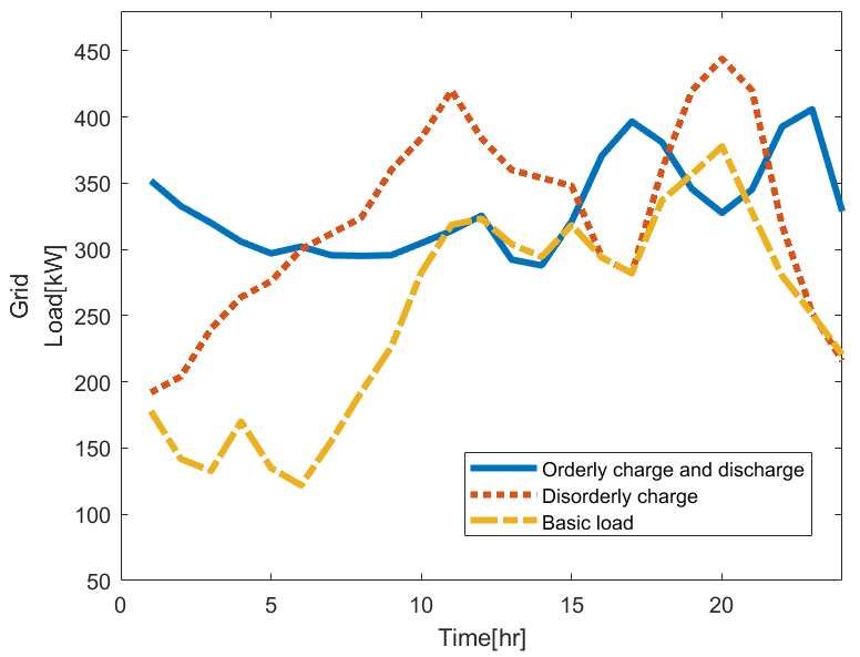
IPEC 2021                                                                                                       IOP Publishing
Journal of Physics: Conference Series                         1952 (2021) 042063          doi:10.1088/1742-6596/1952/4/042063

A V2G scheduling strategy based on the fruit fly optimization
algorithm

                     Muyao Han*
                     College of International Communications, China Three Gorges University, Yichang,
                     China

                     *Corresponding author e-mail: hanmuyao@mail.ctgu.edu.cn

                     Abstract. As electric vehicles enter people’s lives in large numbers, their behavior of
                     disorderly charging and discharging will have a seriously negative impact on the safety
                     and economic operation of the power system. This study proposes an electric vehicle
                     charging and discharging load model under the constraint of joint benefits on the both
                     power supply and demand sides. In this model, we set the minimum variance of grid
                     load peak-to-valley values and the maximum benefit for users as the objective function,
                     and take into account the randomness of electric vehicle starting charging time and
                     duration as well as the grid capacity limitation. The main innovation point is that based
                     on the fruit fly optimization algorithm, it proposes an intelligent orderly charging and
                     discharging strategy with vehicle-to-grid (V2G). Following this, we compare several
                     common charging models for electric vehicles with simulations, and conclude that the
                     proposed optimization model can best reduce the target of peak-to-valley difference in
                     grid load and also charging and discharging costs, thus demonstrating the feasibility and
                     effectiveness of the model and strategy.

                     Keywords: Electric vehicle, orderly charging and discharging, fruit fly algorithm, V2G.

1. Introduction
Given the dual pressure of the energy crisis and environmental degradation, electric vehicles have
received widespread attention as a green way to travel that effectively addresses greenhouse gas
emissions and energy shortages. Meanwhile, as the EVs industry continues to develop, its ownership
has also shown a growing trend, yet large-scale disorderly charging behavior will place a serious burden
on the smooth-running capacity and carrying capacity of the power system, and to a certain extent will
also affect the quality of power. Therefore, it is of great research importance to rationalize the charging
and discharging of EVs reliant on vehicle-to-grid (V2G) technology [1].
   Using the characteristics of EVs as both mobile loads and energy storage devices, V2G technology
guides users to charge and discharge in an orderly manner, complementing distributed energy sources
and reducing the degree of impact on the grid [2-3], while also being able to increase grid revenue and
user charging costs [4]. Current research on modeling with the goal of maximizing the charging profit
of electric vehicles in V2G mode has achieved substantial success by many scholars internationally. In
[5], Vagropoulos et al. introduce an intelligent control method based on time-of-use tariffs to control the
charging periods of EVs by comparing the burden of disorderly charging on the grid. Furthermore,
              Content from this work may be used under the terms of the Creative Commons Attribution 3.0 licence. Any further distribution
              of this work must maintain attribution to the author(s) and the title of the work, journal citation and DOI.
Published under licence by IOP Publishing Ltd                          1
IPEC 2021 IOP Publishing
Journal of Physics: Conference Series 1952 (2021) 042063 doi:10.1088/1742-6596/1952/4/042063
Zhang H et al. establish a real-time tariff trading and charging pile intelligent control model, with its
ability to improve power quality while achieving optimal grid trading profits and ensuring supply-side
reliability [6]. In addition, considering the vehicle battery and the characteristics of the environment in
which it is located, Xie D et al. build a multi-objective ordered charging control system as per different
user requirements [7]. Depending on the orderly charging and discharging management, the [8]
mentioned strategy for large-scale decentralized charging behavior with autonomous decision making
by charging piles, which can manage to guide electric vehicles to play their "energy storage" even in
offline state. And with the operating hours of electric buses, reference [9] is mainly focused on a multi-
time-scale optimal scheduling strategy to integrate into the grid to achieve "peak and valley removal",
but this strategy is highly dependent on bus operating hours and operating modes. To solve the problem
of grid dispatching, Su Shu et al. improve fast-charging stations into predictable ones, guiding users to
change their charging behavior, but without considering factors such as alleviating traffic conditions and
reducing users' charging waiting time.
At present, relatively few scholars have used intelligent optimization algorithms to realize grid
interactive dispatching strategies on the premise that both the supply side and the demand side benefit
from each other. Considering the above, this paper establishes a two-layer optimization model for
charging and discharging EVs: the grid company minimizes the variance of the total load level by
collecting the dispatching plan of each owner in the lower layer and the EV owners, who are motivated
to change the charging and discharging periods of their EVs, should conform to the schedule set by the
grid company and respond to the expected range of total load variance predicted. Meanwhile,
considering the common interests of grid side and customer side, the model develops a time-sharing
charging and discharging tariff scheduling scheme that benefits both sides. Finally the model is chosen
to adopt a newer intelligent optimization algorithm, fruit fly optimization algorithm (FOA) [11], to
optimize the electric vehicle battery discharge strategy, and the feasibility and effectiveness of the model
is verified by simulation.
2. V2G charging and discharging strategy
2.1. Electric vehicle travel time distribution model
Reference [12] conducted data statistics based on the distribution pattern of EVs travel time in real-life
residential areas, through the normalization of the statistical graph data, and fitted that the travel time
approximately obeys a normal distribution.
The EV travel and return trip probability model is shown in equation
The travel distribution density function is:
2
( x 1 )
1 2 1
2
f , ( x) e (1)
1
2 1
1
The return distribution probability density function is:
2
( x 2 )
1 2
2 2
f , 2
( x) e (2)
2
2 2
In the equation, x is the user's travel time and return time, 1 and 2 is the expectation, 1 and 2
are the standard deviation; Among the travel distribution, 1 =8 , 1 =1.33 , the return distribution
parameter is 2 =18.5 , 2 =1.99 , whether or not to go out is then randomly generated and the total
probability of residents traveling is assumed to be 0.8.
The probability density function of the daily mileage of EV is:
(ln x s ) 2
1 2 s2
f s ( x) e (3)
x s 2
2IPEC 2021 IOP Publishing
Journal of Physics: Conference Series 1952 (2021) 042063 doi:10.1088/1742-6596/1952/4/042063
Where, x is the EVs daily mileage. s is the expectation, s is the standard deviation; of which s 3.2 ,
s 0.88 .
2.2. Electric vehicle discharge model
For the study of V2G, the optimal charging power time distribution derived from the load forecast
information and analysis in the literature [8] is used to calculate the discharge margin of the grid in each
time period for providing a data basis for the grid company to make decisions on the behavior of EVs,
while guiding users to orderly charging and discharging.
The charging margin refers to the highest charging load capacity that the grid can allow EVs to bear
in a certain period of time, expressed as the optimized charging load; the discharge margin refers to the
highest load-consuming capacity of EVs discharging to the grid in a certain period of time, expressed
as the difference in power between the peak load discharge offsetting forecast demand and the optimized
load. As a result, the discharge margin model is shown in the equation
ti1 ( P* (t ) P (t ))dt ,P* (i ) P(i )
Pdem (i) ti
(4)
0, P* (i ) P (i)
Where, Pdem (i ) indicates the discharge margin for time period i , P(t ) indicates the charging load at
moment t after optimization, P * (i ) is the forecasted load value of the grid in time period i . When the
predicted charging load in time period i is greater than the optimized charging load, Pdem (i ) is equal to
the integral of the difference between the two in time periods t i to t i1 , otherwise it is equal to 0.
3. Two-layer optimization-based optimal dispatching model for EVs and grids
V2G revenue cost serves as an important means for users to participate in decision-making grid dispatch,
and the reasonable development of time-of-use tariffs can change user charging and discharging
behavior to achieve auxiliary smoothing of grid load fluctuations, while reducing battery losses as well
as power consumption behavior [14]. Based on the time-sharing tariff, the demand side is able to allocate
the grid connection time and charging time for the EVs, both in terms of time cost and revenue cost,
which is more efficient than the traditional unstructured non-time sharing tariff. However, in reality, not
all users are able to actively and positively respond to the charging plan developed by the grid company
owing to the influence of different environments and different travel options, hence it is also necessary
to develop a set of incentives for users to cooperate with V2G to motivate owners to be able to join the
distribution grid dispatching process under the condition of satisfying their own trips. Therefore, in this
paper, we choose to model the minimum grid load variance and the minimum V2G cost, respectively.
3.1. Power grid and user interaction dispatch model
3.1.1. Upper layer optimization model. The upper layer optimization model consists of an upper layer
objective function that contains a range of variance for the total load level of the grid system and 2
incentives developed by the grid company for the actual dispatch results of each agent in the lower layer.
The grid-side load is composed of two parts: the base load available in the grid and the EV charging and
discharging load, so it can be expressed as
1
Fc min
T
[( P(t 1) EVload , t 1) ( P(t ) EVload , t )]2 (5)
Where, P(t 1) and P(t ) denote the base load in the grid at times t+1 and t, respectively, EVload , t 1
and EVload , t denote the load of EVs in time period t, respectively.
Aiming to realize the interaction between the grid and electric vehicles as well as to promote users
to actively change their own charging and discharging behavior, incentives for users to participate in
3IPEC 2021 IOP Publishing
Journal of Physics: Conference Series 1952 (2021) 042063 doi:10.1088/1742-6596/1952/4/042063
smooth load curve behavior are added on the basis of load variance, and the incentive cost R can be
expressed as
R FcT (6)
Where, denotes the reward factor for users who meet the grid company's load variance target, and
its value depends on the grid's target variance for the day. T denotes the total number of time periods
during which users participate in orderly charging and discharging behavior and meet the grid
requirements.
Constraint Conditions
When electric vehicles are integrated into the grid for power transmission in a disorderly manner, the
capacity of the distribution grid is affected to a certain extent owing to the increase in quantity and the
difference in battery capacity, which might form a new load peak-to-valley difference. Consequently,
the grid company sets the value of the allowable range of load variance at the level of user behavior
rewards, which enables the electric vehicle behavior to help the distribution network to a great extent to
meet the grid company requirements. The mathematical expression for the given user reward constraint
is
R,Fc Fc , s
(7)
0, Fc Fc , s
Where, Fc , s indicates the maximum value of the allowed range of expected load variance based on
the comprehensive analysis of the recent power consumption by the grid company. Only when the
variance of the grid load after adding the scheduling strategy is less than the expected value of the grid,
the customer can get the corresponding reward. If the electric vehicle does not reach the expected range
due to factors such as charging and discharging duration or battery capacity, the user will not be
rewarded. The simulation results show that the load variance as the target for the distribution network
for peak and valley reduction can indeed smooth the load power to a certain extent, and accomplish the
requirements for vehicle cluster load transfer in a small area, so that the user charging and discharging
costs are reduced on the basis of disorderly charging, however, it still cannot solve the load bearing
pressure on the grid side during the peak load hours of the peak electricity consumption period, and the
load fluctuation of the distribution system still exists.
3.1.2. Lower layer optimization model. V2G strategy is not only related to user-side cost optimization,
but also usually involves grid losses, load balancing and other practical problems. It is impossible to
achieve the expected efficient operation mode of the grid simply by controlling the variance coefficient
for peak-shaving and valley-filling, so considering the relevant factors affecting load fluctuation on both
grid side and user side can improve the stable operation of the grid, thus developing user charging and
discharging cost optimization as the lower layer optimization model.
Given that the user side has a more diversified choice of charging methods due to different travel
reasons and travel frequency, grid companies can develop multiple types of charging modes and
charging pricing that meet user needs. Meanwhile, electric vehicles have dual characteristics of charging
and discharging as mobile energy storage devices, and they can also be used as random distributed power
sources to deliver electricity to the distribution network, allowing users to obtain discharge gains while
helping the distribution network system to operate stably. With the constraints and incentive mechanism
of peak and valley reduction coefficients, the discharge gains of users Bu can be expressed as
Bu wu , s ( ) pEVu ,c (t ) R (8)
Where, pEV denotes the amount of electricity discharged by an electric vehicle at a charging post in
a residential neighborhood or parking lot, the value of which depends on the value of the electric power
that the customer expects the electric vehicle to transmit to the distribution system. wu , s ( ) is the user-
side discharge decision factor, the value of which is determined in relation to whether the user chooses
4IPEC 2021 IOP Publishing
Journal of Physics: Conference Series 1952 (2021) 042063 doi:10.1088/1742-6596/1952/4/042063
to have the electric vehicle charged or not. u ,c (t ) denotes the time-of-day discharge tariff (yuan/kwh)
developed by the grid company based on system operation and revenue costs.
Combining the above influencing factors, the charging and discharging cost Cuc of electric vehicles
can be expressed as
N N J
Cuc ch Bu k (1 ) PEV ,t v1 (t )(tend t start ) k ( 2 ) PEV ,t v 2 (t )(tend t start ) (9)
i 1 i 1 j t 1
Where, ch denotes the grid-side discharge decision factor, the value of which depends on the length
of time the electric vehicle is connected to the grid for charging and discharging. k (1 ) is the fast
charging decision variable, if the user chooses fast charging according to his travel situation, then k (1 )
=1, conversely, k (1 ) =0; k ( 2 ) is the slow charging decision variable, if the user decision outcome
is slow charging of electric vehicles, then k ( 2 ) =1, conversely, k ( 2 ) =0, and the fast and slow
charging decisions do not hold simultaneously during the conventional charging process, i.e. k (1 ) and
k ( 2 ) cannot be 1 at the same time; v1 (t ) is the slow charging tariff (yuan/kwh), v 2 (t ) is the fast
charging tariff (yuan/kwh), Both of them are divided into peak, low and flat periods within a day
according to the changes of the grid load, and different tariffs are formulated for the characteristics of
the load curve in different periods to encourage users to choose the charging mode and charging time
reasonably, which has the effect of peak and valley reduction, and v1 (t ) u ,c (t ) v 2 (t ) ; PEV ,t
denotes the total charging power in time period t where the electric vehicle is located. tstart and tend
denotes the starting moment and the leaving moment of the electric vehicle user's access to the charging
pile, respectively.
Constraint Conditions
①User-side discharge decision factor constraint
1, Electrical vehicles are involved in discharges
wu , s ( ) (10)
0,Electrical vehicles are not involved in discharges
②Electric vehicle charging behavior when fast charging and slow charging can not be carried out at
the same time
k (1 )+k ( 2 ) 1 (11)
③Grid-side discharge decision factor constraint
1, Tch Tch
ch (12)
0, Tch Tch
Where, Tch denotes the total time of continuous charging and discharging of the user to the grid.
Tch denotes the minimum access dwell time to the grid for which grid companies specify that electric
vehicles are allowed to take discharge measures. It guarantees that when leaving the grid, the SOC of
the electric vehicle will still ensure normal travel for the user even if the user selects the discharge mode
due to other conditions by terminating the interaction between the electric vehicle and the distribution
network in advance.
④Safety constraints on battery operation
SOCmin SOCn,t SOCmax (13)
Of which, SOCmin and SOCmax denotes the maximum and minimum values of the electric vehicle
charge state, respectively.
5IPEC 2021 IOP Publishing
Journal of Physics: Conference Series 1952 (2021) 042063 doi:10.1088/1742-6596/1952/4/042063
⑤Power constraints for charging and discharging of electric vehicles in adjacent time periods
EVload ,t 1 EVload ,t EVp min (14)
Of which, EV p min denotes the maximum charging power allowed in adjacent time periods under
electric vehicle charging status.
⑥Electric vehicle charging and discharging capacity constraints
ch PN ,t (tend tstart )
SOC N ,t , wu ,s ( ) 0
SOCm
SOCN ,t 1 (15)
SOC sp PN ,t (tend tstart ) , w ( ) 1
N ,t
SOCm
u ,s
Where, SOCN ,t denotes the state of charge at the end of moment t when the electric vehicle is
connected to the grid. ch and sp denotes the charging efficiency and discharging efficiency of
charging piles in residential neighborhoods or parking lots, respectively. PN ,t denotes the charging and
discharging power provided by the user's choice of grid connection mode. SOCm denotes the battery
capacity in the user's electric vehicle.
⑦Unschedulable time constraints
wu , s ( ) 0
k (1 ) 0 , N , t tstart OR tend (16)
( ) 0
k 2
Where, if the charging period t is smaller than tstart or tend , it is impossible for the grid company to
schedule EVs charging and discharging behavior, which means wu , s ( ) , k (1 ) and k ( 2 ) all equal to
zero.
4. V2G scheduling strategy for electric vehicles based on fruit fly algorithm
4.1. Fruit fly algorithm
As the intelligent algorithms continuously improve and develop, many studies have achieved good
results for the processing of multi-optimization problems, especially about the optimization problem of
orderly charging and discharging of electric vehicles, most scholars at home and abroad choose to take
Particle Swarm Optimization, PSO algorithm to find the optimal solution of the problem in the grid or
user strategy [15-17], however, PSO suffers from the disadvantages of slow computation speed and easy
to fall into local optimum, which has a great degree of influence on the accuracy of the algorithm. Newer
group intelligence optimization algorithms, the fruit fly optimization algorithm principle is easy to
understand, easy to implement programmatically, has fewer control parameters, and is easy to embed in
specific search sessions targeted to the problem. Due to the convenience and speed of the Drosophila
optimization algorithm to deal with optimization problems, it has been successfully applied to network
energy efficiency optimization, logistics, planning, and scheduling problems in a relatively short time
[18-20]. In recent years, the algorithm is gradually being applied to positioning in the case of electric
vehicles connected to the grid [21], with good results.
4.2. Algorithm Process
According to the fruit fly optimization algorithm, the steps for optimizing the layout of EV charging
stations in this paper are shown in Figure 1.
6IPEC 2021 IOP Publishing
Journal of Physics: Conference Series 1952 (2021) 042063 doi:10.1088/1742-6596/1952/4/042063
Step 1: The original parameters are set and initialized for data processing, including user electric
vehicle charging and discharging information (charging and discharging power, battery capacity,
charging demand, etc.) and parameters such as grid-side base load information and predicted load
variance are set.
Step 2: Depending on the scope of the target area, the charging and discharging load power in
different areas at different times is calculated and the charging and discharging driving cost of users is
converted.
Step 3: Optimized values in each range are found by updating the calculated particles by fitness
Step 4: Determine whether the maximum number of iterations is exceeded, if not, repeat steps 2 and
3, and vice versa to find out the optimal particle positions and adaptation values with respect to different
charging and discharging strategies, and end the simulation.
Figure 1. Operation process of the fruit fly optimization algorithm
5. Example analysis
5.1. Parameter Setting
In this paper, the formal characteristics of domestic electric vehicles and grid base load curves from the
literature [8] are used as references. For ensuring that the maximum optimization of user-side charging
and discharging costs is reached, wu , s ( )=1 and ch =1 , namely, all users select the slow charging mode
and agree to participate in the discharge decision and the grid connection time meets the specified length.
The grid sets tariffs in the form of time-of-day tariffs. The time-of-day tariff is divided into 3 periods:
peak, usual and valley, and the grid company sets the corresponding tariff for each period. With the aim
of providing a better charging experience and power quality, as well as motivating users to choose to
7IPEC 2021 IOP Publishing
Journal of Physics: Conference Series 1952 (2021) 042063 doi:10.1088/1742-6596/1952/4/042063
consume as much as possible when the price is lowest in the valley and discharge to the grid when the
revenue is highest in the peak time, a time-sharing tariff has been implemented in some areas on a trial
basis, with the specific development of charging and discharging price parameters set as shown in Table
1. If we suppose that the charging station provides charging service for 24 private electric vehicles per
day, and analyze the general habits of residential users in using electric vehicles, we find that the
distribution of users' starting charging time and charging capacity conforms to a normal distribution
N (18,32 ) .
The research time starts from 1:00 and ends at 24:00 on the next day. For the sake of more intuitive
and simple research results, we set the time gap as 1 hour, that is, 1 day is divided into 24 periods, 1:00-
2:00 is 1 period, and so on. Based on the analytical calculation of the grid base load in the literature [8],
we assume that the grid company expects the maximum value of the range of daily load curve variance
to be 834, i.e. Fc , s 834 .
Table 1. Charging station charging and discharging tariff parameter settings
Slow charging tariff / Regular discharge tariff /
Time period -1 -1
(Yuan·(kW·h) ) (Yuan·(kW·h) )
Valley time (0:00-3:00, 22:00-
0.200 0.300
24:00)
Usual time (3:00-7:00, 15:00-
0.862 0.906
17:00)
Peak time(7:00-15:00,17:00-
0.558 0.668
22:00)
5.2. Disorderly and orderly charge/discharge simulation
Aiming at verifying the actual control effect of the model strategy on orderly charging, we first calculate
the load of distribution system and the benefit of user charging and discharging in the case of disorderly
charging, then compare and analyze the arithmetic results with the case of orderly charging. When
charging in an unordered manner, new entrants can be charged as long as there is space available at the
charging station, until the user leaves, otherwise the charging should stop if the electric vehicle battery
is full. Prior to the electric vehicle being connected to the grid, the grid system itself contains
comprehensive power consumption in residential areas and line network loss consumption to form a
base load with large power differences at various times. However, when electric vehicles are integrated
into the grid in a disorderly manner, the charging station may overload the distribution transformer
during peak hours of power consumption due to the access of a large number of electric vehicles, or the
user's demand may be urgent, requiring the state of charge in a short period of time, then occur the
situation that the battery cannot be fully charged when leaving even if the electric vehicle has been
charging. While in the case of orderly charging and discharging, no increase in the peak-to-valley
difference in the base load curve after accessing electric vehicles according to the guidance of the time-
sharing tariff strategy developed in advance, while the user cost is also reduced compared to disorderly
charging. As a result, the time-sharing tariff strategy in the context of unordered charging remains
ineffective in solving the problems of load fluctuation and minimum cost for users in the distribution
network during the peak electricity consumption period, while ordered charging can provide problem
solving options.
5.3. Simulation results based on the fruit fly optimization algorithm
Optimization analysis is carried out by fruit fly algorithm according to the selected parameter settings
with the maximum benefit cost of user discharge as the objective function, and the calculation results
under the disorderly charging mode and the orderly charging mode are calculated, in which the optimal
8IPEC 2021 IOP Publishing
Journal of Physics: Conference Series 1952 (2021) 042063 doi:10.1088/1742-6596/1952/4/042063
discharge power curve is superimposed on the conventional load and the electric vehicle charging load
in the grid to obtain the daily load expectation curve and the conventional load curve under the two
modes of disorderly charging and orderly charging.
5.4. Result Analysis
Table 2 is derived from the model data results and analyzes that the user cost decreases by 2.5 times in
the orderly charging mode compared with the disorderly charging mode, which proves that the
interaction between the user's orderly charging and discharging and grid dispatching is conducive to
achieving the optimal demand-side benefit on the premise of meeting the stable operation of the grid.
From Figure 2, we can see that when this strategy adopts the orderly control of electric vehicle charging
and discharging, after 24 electric vehicles are integrated into the grid, the minimum load value is
increased from 192 KW to 287.875 KW after optimization, and the peak-to-valley difference is reduced
from 252 KW in disorder to 108.783 KW after optimization, and the load power variance in the grid is
reduced from 4982 kW2 to 1085.66 kW2, with obvious effect of "peak reduction" during the peak hours
of electricity consumption. It also effectively adjusts the charging behavior moment to 1:00 to 4:00,
while the discharging behavior is concentrated in the two peak hours of electricity consumption from
9:00 to 13:00 and 18:00 to 20:00. Compared with the charging and discharging tariff, the higher rebate
reward can be obtained by choosing to discharge to the grid in these two periods compared with other
periods. With the fruit fly optimization, this scheduling scheme can indirectly assist the grid to reduce
the peak-to-valley difference of the load curve and play the role of peaks and valleys reduction while
achieving the goal of saving users' charging cost.
Table 2. Charging and discharging costs of electric vehicles under different modes
Charging and discharging cost Orderly charge and
Disorderly charge
model discharge
Charging cost(yuan) 4328.46 4096.50
Discharge earnings(yuan) 0 2379.53
Total(yuan) 4328.46 1716.97
Table 3. Load variance of distribution network system under different modes
Orderly charge and
Mode Basis load Disorderly charge
discharge
Load variance/kW2 7124.41 4982 1085.66
Figure 2. Comparison among disorderly charging and optimal charging and discharging
9IPEC 2021 IOP Publishing
Journal of Physics: Conference Series 1952 (2021) 042063 doi:10.1088/1742-6596/1952/4/042063
Consequently, this calculation shows that the V2G mode dispatching strategy for home electric
vehicles that sets the load variance range on the grid side and maximizes the charging and discharging
costs for vehicle owners can motivate electric vehicle users to participate in grid dispatching interactions,
with a mechanism to provide incentives for discharging to the grid helping to promote the goal of user
response to the time-of-use tariff. Simultaneously, this example also proves that a scientific and
reasonable electric vehicle dispatching strategy can provide technical support to the "peak and valley
reduction" scheme of the distribution network and effectively help the grid system maintain a stable
operation.
6. Conclusion
This paper mainly deals with the application of V2G strategy based on FOA for home EVs in residential
communities, which sets the expected range of grid load variance affected by the grid connection of
electric vehicles by analyzing the actual grid base load distribution, while considering various
constraints such as decision factors of both sides, battery capacity and charging and discharging power.
It is demonstrated that the strategy can promote the users to respond to the grid company's proposal by
comparing the grid load power under the disorderly charging mode, thereby enabling the access of
electric vehicles to achieve the goal of smoothing the electricity load curve in the distribution system,
realizing the goal of grid peaks and valleys reduction, and ensuring the stability of grid system operation
and power quality.
The proposed scheme is based on the behavior of clustering vehicles in a small area, while the user
chooses to participate in the optimal scheme to the maximum extent to achieve the minimum charging
cost. The charging behavior of electric vehicles is directly related to the load fluctuation on the
distribution side, while in reality, users cannot prefer such strategies as per their own travel needs at the
moment, season, weather and other factors. Consequently, it is advisable to consider the response of
users' multifaceted travel factors to their charging and discharging behaviors under different scenarios
in the subsequent study in conjunction with the actual situation.
References
[1] Alam M, Muttaqi K M, D Sutanto. Effective Utilization of Available PEV Battery Capacity for
Mitigation of Solar PV Impact and Grid Support With Integrated V2G Functionality[J]. IEEE
Transactions on Smart Grid, 2017, 7(3):1562-1571.
[2] YANG H, PAN H, LUO F, et al. Operational planning of electric vehicles for balancing wind
power and load fluctuations in a microgrid[J]. IEEE Transactions on Sustainable Energy, 2017,
8(2).
[3] NIEY, CHUNG C, XU N. System state estimation considering EV penetration with unknown
behavior using quasi-Newton method [J]. IEEE Transactions on Power Systems, 2016, 31(6):
4605-4615.
[4] Cheng Suan, Wang Xianning, Feng Yi Brazier. Decentralized optimization of orderly charging
scheduling for electric vehicle charging stations[J]. Power System Automation,
2018,42(01):39-46.
[5] Vagropoulos S I, Balaskas G A, Bakirtzis A G. An Investigation of Plug-In Electric Vehicle
Charging Impact on Power Systems Scheduling and Energy Costs[J]. IEEE Transactions on
Power Systems, 2017, 32(3):1902-1912.
[6] Zhang H, Hu Z, Xu Z, et al. Evaluation of Achievable Vehicle-to-Grid Capacity Using Aggregate
PEV Model[J]. IEEE Transactions on Power Systems, 2017, 32(1):784-794.
[7] Xie D, Chu H, Gu C, et al. A Novel Dispatching Control Strategy for EVs Intelligent Integrated
Stations, IEEE Transactions on Smart Grid, 2017,8(2):802-811.
[8] Wang Yi, Ma Xiu, Wan Yi, Hou Xingzhe, Zheng Ke, Chen Wenli. Orderly charging and
discharging guidance strategy for electric vehicles based on time-sharing charging and
discharging margins[J]. Power Grid Technology, 2019,43(12):4353-4361.
[9] Chen Lijuan, Qin Meng, Gu Shaoping, Qian Kejun, Xu Xiaohui. Optimal scheduling strategy for
10IPEC 2021 IOP Publishing
Journal of Physics: Conference Series 1952 (2021) 042063 doi:10.1088/1742-6596/1952/4/042063
electric buses participating in V2G taking into account battery losses[J]. Power System
Automation,2020,44(11):52-60.
[10] Su Shu, Lin Xiangning, Zhang Hongzhi, Zhao Hang, Li Hao, Li Zhengtian. Dynamic evolution
model of spatial and temporal distribution of electric vehicle charging demand[J]. Chinese
Journal of Electrical Engineering, 2017, 37(16):4618-4629+4887.
[11] Fan Y, Wang P, Heidari A A, Wang M, Zhao X, Chen H, Li C. Rationalized fruit fly optimization
with sine cosine algorithm: A comprehensive analysis[J]. Expert Systems With
Applications,2020,157.
[12] Shi Ruifeng, Liang Zihang, Ma Yuan. An orderly charging strategy for electric vehicles in
residential areas based on TOPSIS method[J]. Power System Automation, 2018,42(21):104-
110+159.
[13] Cui Jindong, Luo Wenda, Zhou Niancheng. Research on the pricing model and strategy for
orderly charging and discharging of electric vehicles based on multiple perspectives[J].
Chinese Journal of Electrical Engineering,2018, 38(15):4438-4450+4644.
[14] Zhang H, Hu Z, Xu Z, et al. An Integrated Planning Framework for Different Types of PEV
Charging Facilities in Urban Area[J]. IEEE Transactions on Smart Grid, 2017, 7(5):2273-2284.
[15] Li Xianshan, Chen Minrui, Cheng San, Chen Aobo. Optimal scheduling strategy for electric
vehicle microgrid based on double incentive cooperative game[J]. High Voltage Technology,
2020, 46(07):2286-2296.
[16] Ma Xiufan, Wang Hao, Li Ying, Wang Chao, Hong Xiao. Electric vehicle charging station
planning based on variable-weight Voronoi diagram and hybrid particle swarm algorithm[J].
Journal of Electrical Engineering Technology, 2017, 32(19):160-169.
[17] Xu Fangwei, Tan Yangyang, Yang Hongkeng, Teng Yufei, Zhang Xi, Yin Qing. Optimal layout
of centralized charging stations taking into account the interests of different players[J]. High
Voltage Technology, 2017, 43(04):1256-1262.
[18] Liu Yong, Sun Jingjie, Wang Xuan. Research on multiple distribution center site selection
problem based on immune fruit fly hybrid optimization algorithm [J]. World Science and
Technology Research and Development, 2015, 37(1) : 83-87.
[19] Bian X Y, Yan G, Lo K L, et al. Coordination of PSSs and SVC Damping Controller to Improve
Probabilistic Small-Signal Stability of Power System With Wind Farm Integration[J]. IEEE
Transactions on Power Systems, 2016, 31(3):1-12
[20] Yuan Wenbing, Chang Liang, Xu Zhoubo, et al. Multi-station assembly sequence planning based
on fruit fly optimization algorithm [J]. Computer Science, 2017, 44 (4) :246-251.
[21] Wan Xiaofeng, Xi Ruixia, Hu Hailin, Wan Xiaoli. Research on multi-objective optimal control
of grid-connected inverters during grid imbalance based on fruit fly algorithm[J]. Power Grid
Technology, 2018,42(05):1628-1635.
11You can also read