ABSTRACT - Royal Aeronautical Society
←
→
Page content transcription
If your browser does not render page correctly, please read the page content below
Journal of Aeronautical History                                             Paper 2020/04

               The Royal Aircraft Establishment Farnborough
         100 years of Innovative Research, Development and Application

                                       Dr Graham Rood

                           Farnborough Air Sciences Trust (FAST)
           Formerly Head of Man Machine Integration (MMI) Dept. RAE Farnborough

                                         ABSTRACT

Aviation research and development has been carried out in Great Britain for well over a
century. Starting with balloons in the army at Woolwich Arsenal in 1878, progressing through
kites and dirigibles in 1907, through to the first practical aeroplanes, the B.E.1 and B.E.2,
designed and built by the Royal Aircraft Factory in April 1911. At this time Mervyn O’Gorman
was installed as the Superintendent of the Army Aircraft Factory and began to gather the best
scientists and engineers and bring scientific methods to the design and testing of aeroplanes.
Renamed the Royal Aircraft Factory (RAF) in April 1912, it designed, built and tested aircraft,
engines and aircraft systems throughout WW1. In 1918 its title was changed to the Royal
Aircraft Establishment (RAE) to avoid confusion with the newly formed Royal Air Force.
From then on RAE Farnborough and its outstations, including Bedford and Pyestock, developed
into the biggest aviation research and development establishment in Europe and one of the best
known names in aviation, working in all the disciplines necessary to build and test aircraft in
their entirety. On the 1st April 1991 the RAE ceased to exist. The Establishment was renamed
the Aerospace Division of the Defence Research Agency (DRA) and remained an executive
agency of the UK Ministry of Defence (MOD). It was the start of changing its emphasis from
research to gain and extend knowledge to more commercially focussed concerns.

1.       INTRODUCTION

The problem of compressing 100 years of the Royal Aircraft Establishment (RAE)’s research,
development and innovation into a short article risks understating the breadth and depth of the
advances made in aviation science and technology by the RAE. At the risk of alienating many
of those who worked at RAE and whose speciality and expertise cannot be included I have
tried to summarise many of those things that RAE did well and tried to bring out the innovations
of some of the less ‘glamorous’ departments. It is inevitable that this paper highlights a sequence
of interesting and significant projects, rather than providing a comprehensive account of the full
scope of the Establishment over the past hundred years. The RAE was not only Farnborough
but also outstations such as Bedford and (at times) Pyestock and ranges such as Aberporth.

The Royal Aircraft Establishment was formed in 1918 when the Royal Aircraft Factory (RAF)
and the newly formed Royal Air Force (RAF) ended up with the same initials. To avoid
confusion ‘Factory’ was changed to ‘Establishment’ - thus, the Royal Aircraft Establishment
was named.

                                                53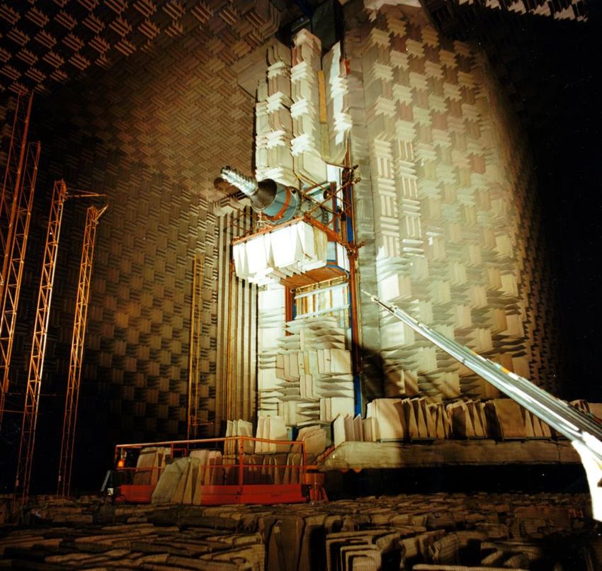
Journal of Aeronautical History                                        Paper 2020/04

However, to give a more complete historical context it is necessary to start earlier, when the
Royal Engineers’ Balloon School first moved to its Farnborough site on the Swan Plateau
(Figure 1). The move was from Balloon Square in Aldershot at the end of 1905, bringing a
single balloon shed and constructing on the site an airship shed, some workshops and a hydrogen
generation station. At the time the main interest of the army was in using balloons for
reconnaissance and the move to Farnborough was to allow the necessary space to start work on
the bigger powered dirigibles which, they surmised, would be the future of aerial operations.(1)

Because balloons could only be used when there was little or no wind, man-carrying kites were
developed for use in windy conditions, led by Samuel Cody, and this was followed by heavier-
than-air machines by the Wright brothers in the USA in 1903/5, by Samuel Cody in Britain in
1908 and by Louis Bleriot, amongst other French pioneer aviators. When Bleriot spanned the
English Channel in 1909 the War Office, perhaps realising that Great Britain was no longer a
secure island, began to view aviation and its military potential in a more advantageous light.

                     Figure 1 The Balloon Factory in 1906 on the Swan Plateau
                          just after its move from Balloon Square, Aldershot

1.1       The start of scientific development of aeronautics

The real basis for scientific advance in aviation was started when Mervyn O’Gorman was
appointed the civilian Superintendent of the newly formed Royal Aircraft Factory in December
1909. He brought the beginning of a coherent structure to aviation research, introduced
scientific method to the development of aeronautics and recruited the first true aeronautical
scientists and engineers. The work of the Factory included airships, aircraft and engines.

                                               54
Journal of Aeronautical History                                             Paper 2020/04

In January 1910 F M Green, one of O’Gorman’s early acquisitions from the Daimler
Company, on the recommendation of Dr F W Lanchester, joined the Factory as ‘Engineer in
Charge of Design’ (E.D.). He was directly responsible for the design of the Beta, Gamma and
Delta airships, most of the aeroplanes from the S.E.1 to the B.E.1 and all the engines from the
RAF 1A in 1913 up to 1916. Later, in 1945, he described the 1910 beginnings of scientific
method:
   ‘…rational methods of stress calculations were developed and introduced into the
  technique of design, and strength testing of complete structures was started. Calculation
  of stability and control began to take the place of inspired guesses, and design ceased to
  be purely an art and became more of a science’ (2).

Through use of these methods the Factory began to develop more efficient aeroplanes and
better understand and control many of their irregularities. By the beginning of the Great War it
had ready for production two effective machines - the B.E.2 and its derivatives (Figure 2), and
the pusher F.E.2.

    Figure 2. Geoffrey de Havilland in a B.E.2/2a with the RFC/Inspection ‘Black’ Sheds
                             in the background in May 1912

Considerable advances in all areas of military aviation were made in WW1 which were not,
theoretically, part of the later RAE’s R&D but which strongly influenced the future of the
Royal Aircraft Establishment. At the end of the war the Factory had developed significantly
and had formed some eleven scientific departments researching into full scale flight and all the
other scientific and engineering processes that are needed to support safe and effective flight
(Figure 3a). This was the structure that RAE inherited in April 1918 (or June if you read other
histories), but by 1922 it had developed into the organisation shown in Figure 3b.

                                               55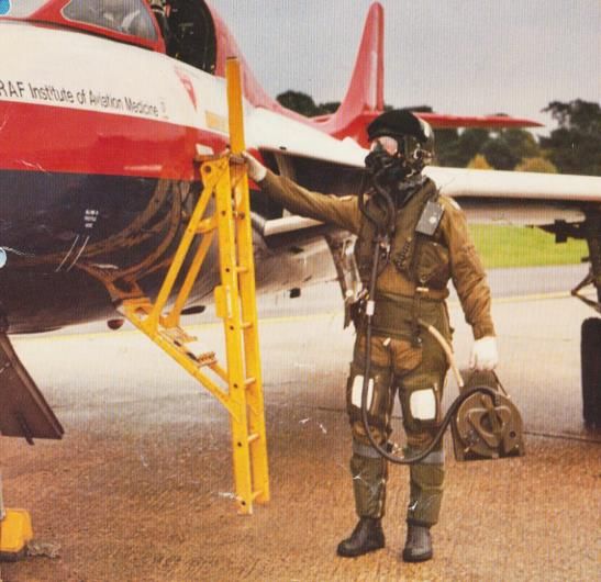
Journal of Aeronautical History                                           Paper 2020/04

Figure 3a. This 1914-16 organisational chart is the closest available to the RAE structure in 1918, apart from the change of Superintendent of
 the Factory to Henry Fowler in September 1916, replacing Mervyn O’Gorman, and then by W. Sydney Smith in March 1918. It is indicative
                                 but considered to be accurate in the number, type and size of departments.

                                                                     56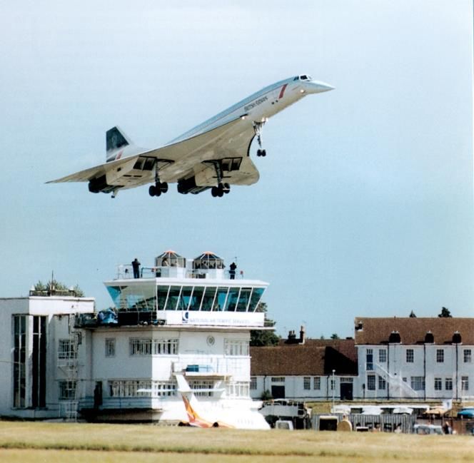
Journal of Aeronautical History                                          Paper 2020/04

                       Figure 3b   The organisational chart for RAE in 1922

                                          57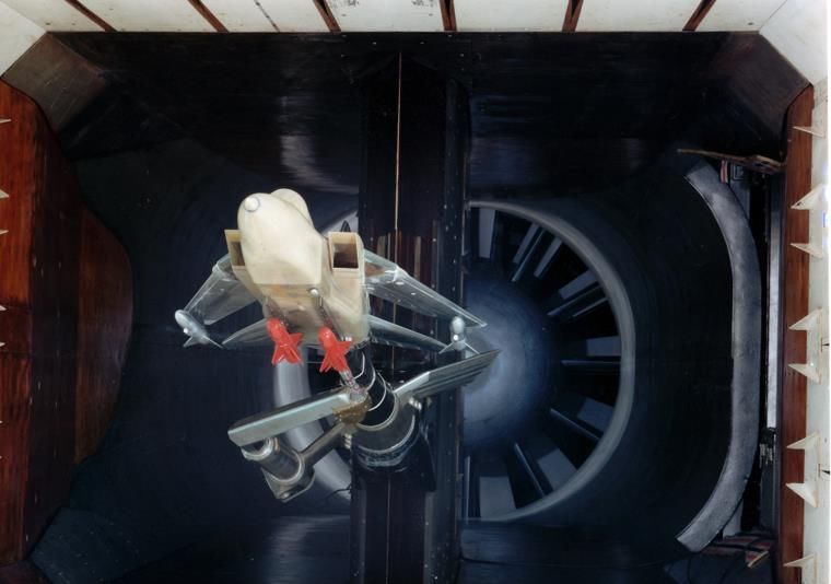
Journal of Aeronautical History                                            Paper 2020/04

Figure 3b shows the organisation in 1922 by which time the transition from the WW1 footing
had been completed and the organisational structure was set – with a few modifications and
additions over the years – until well past WW2. In the Production section, running the Fabrics
Shop, is Vivian Cody, son of Samuel Cody, who remained Head of Fabrics Division right
through to his retirement in 1950 and was, in due course, succeeded by his son Leslie. The
Fabric Shop was always known just as “Cody’s”.

1.2       Post-war financial cut-backs

As with the cessation of all conflicts, certainly in Great Britain, the end of WW1 was followed
by large reductions in Treasury funding and thus resources and staff available to support research.
The Establishment funding reduced to about 20% of its 1918 figures. In 1917/8 the total number
of employees was 5,052 which, by 1920, had fallen to 1,380 - a reduction of some 73%.

However, there remained a few positives with the Trade Lads School (Apprentice training)
being established in 1918. In 1922 the Wireless and Photographic Departments arrived from
Biggin Hill and Airworthiness and Contracts Supervisions from the Air Ministry.

The financial stringencies hit the work at Farnborough and over the next few years research
and development continued but at a considerably reduced level. RAF/RAE had been developing
variable pitch propellers and had carried out ground trials on the whirling arm and flight trials
with an S.E.5a and a B.E.2. Hermann Glauert – one of Aerodynamics Department’s
distinguished scientists - had developed “The Elements of Aerofoil and Airscrew Theory”
(R&M 786) in 1922, published as a text book in 1926, which contributed significantly to the
world’s understanding of the design of wings and propellers (3, 4). Louis Brennan had begun
the construction of a helicopter at Farnborough in 1919, the development of which stretched
through six years to 1926 with some 300 flights before being abandoned with the advent of the
Autogiro which did much of the same job in a simpler form (Figure 4).

By 1922 the total number of staff stood at 1,316, comprising 250 Scientific and Technical
including RAF officers, 85 clerical, 626 skilled including apprentices and 335 labourers and
general workers (Figure 5 shows the extent of the establishment in the 1920s).

In 1924 further savings in funding were proposed and the Halahan Committee was formed and
tasked to
   “examine the present organisation of the Royal Aircraft Establishment and to report
   what steps, if any, should be taken to reduce the cost without impairing its value as an
   experimental establishment in peacetime or its capacity to expand in an emergency”. (5)
The findings concluded that “The primary function of the Establishment is that it should
provide a full-scale aeronautical laboratory for the Air Ministry with its main activities being:
   1.    Development work on experimental aeroplanes and engines
   2.    Testing of experimental instruments and accessories
   3.    Development of special flying instruments for which there is little commercial demand
   4.    Investigation of failures

                                                58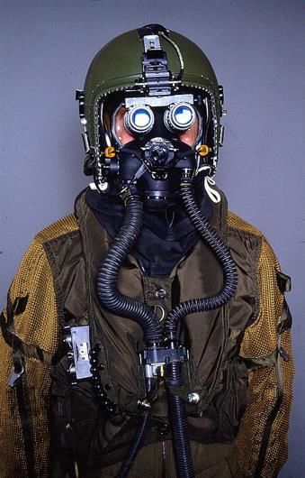
Journal of Aeronautical History                                             Paper 2020/04

    Figure 4.   Louis Brennan poses in front of his helicopter on the airfield with the Black
                                Sheds in the far background

In addition, there were subsidiary functions for the support of HQ and RAF
  5. Liaison with contractor’s research
  6. Technical supervision of the construction of experimental aircraft
  7. Stressing of new types of aircraft, approvals of designs for these and recommendations
     for the issue of airworthiness certificates
  8. The issue of certain technical publications
This resulted in the Establishment progressing in much the same way but with a close eye on
expenditure and finding innovative ways of getting round financial inconveniences - a process
in which they excelled into the future.

   Figure 5. An aerial view of RAE in the 1920s showing the extent of the research facilities
  and supporting workshops. The airfield extends to the left of the picture in front of the Black
           Sheds (originally the Inspection and RFC sheds, and not yet painted black)

                                               59
Journal of Aeronautical History                                              Paper 2020/04

2.       UNMANNED AIRCRAFT

The RAE has always had an involvement in unmanned aircraft (UMA), starting in 1914 when
they worked on the development of a radio-controlled UMA to attack Zeppelins which were,
for security purposes, called the Aerial Target (AT). Not used during the Great War,
development went on at a low level but with flight trials undertaken. In 1927 a better-developed
machine – the Larynx – was completed and was designed to carry a 250 lb bomb a distance of
300 miles (Figure 6). This proved successful but it did not spark interest in the Air Ministry
who presumably were having trouble finding funding for conventional squadron aircraft and
were probably not keen to hasten the demise of the human pilot. In brief, this direction of
research included the provision of proper Aerial Targets using conventional bi-planes under
radio control as targets for gunnery (the Fairy Queen and developments) to the post WW2 X-
RAE Unmanned Aircraft to the current Zephyr solar-powered long-duration very-high-altitude
surveillance machines.

 Figure 6. RAE Larynx No.3 prepares for flight from HMS Stronghold on the 19th October
 1927 with a future Director of RAE, George Gardner, standing between the wing and tail unit.

3.       WIND TUNNELS

A competent aviation research establishment needs to have a comprehensive range of facilities
that allow ground testing of aircraft designs and systems prior to flight testing. One of the
foremost is the use of wind tunnels to develop and refine the aerodynamic performance of a
future aircraft - which is considerably less costly than modifying aircraft once fully constructed.
The other significant advantage is that scientific and engineering measurements and changes
can be made in a controlled, consistent and repeatable environment. In the early part of the
20th Century the National Physical Laboratory had led much of the aeronautical research and

                                                60
Journal of Aeronautical History                                          Paper 2020/04

had several wind-tunnels. By 1907 the Factory had a small tunnel and by 1917, R52 building
had been constructed as the ‘Small wind tunnels’ building and contained two seven-foot
working section tunnels (Figure 7).

Figure 7 An aerial view of RAE taken in 1950 with the wind tunnels area shown marked in
red in the top right-hand of the image. Also shown in the top left-hand corner are the crescent
   of RAF accommodation buildings built in WW1 and called the RAFBOROUGH estate

3.1       The 24 ft tunnel and engine cooling

In the early 1930s it was realised that larger tunnels were needed and in 1930 recommendations
were made for a tunnel which could be used for the current and predicted problems of future
aircraft designs. These included the cooling of air- and liquid-cooled engines, the reduction of

                                                61
Journal of Aeronautical History                                              Paper 2020/04

drag on aircraft and engine cowlings, the development of full scale airscrews and experiments
on large aircraft and component parts of aeroplanes such as gun turrets, cockpit canopies, etc.

The tunnel was specifically designed to be able to run engines with a fresh-air intake and exhaust
extraction system either side of the working section. In April 1932 work commenced and on
April 4th 1935 the 24 ft tunnel was opened by the Secretary of State for Air, the Marquis of
Londonderry. It was an open-working-section closed-return tunnel with a 24 ft working section,
the airflow being generated by a 30ft mahogany fan with airspeeds of up to 120 mph. Until it
was closed in the 1990s the tunnel was used for testing full scale aircraft (Hurricane, Whirlwind,
Pou de Ciel, etc., Figure 8), air-cooled and fluid-cooled engines, fir trees for the Forestry
Commission, motor cars for Jaguar, Austin and Vanwall, advanced helicopter rotor blades, jet
engines for the Meteor nacelle design and finally, amongst many other experiments, the high
incidence research models – for post- or near-stall manoeuvring, in the early 1990s.

For the aerodynamicists at Farnborough (and anywhere else) the last thing they needed were
protuberances extending into the airstream and interfering with aerodynamic efficiency whilst
for the engine researchers at Farnborough there was a need to fit ducts that were large enough
to provide the cooling necessary for the engine. This balance between the drag caused by the
necessary cooling ducts and the aerodynamic efficiency (for high speed with the available
power) becomes more important the higher the speed and had been a constant problem for
aircraft designers, much exercised in the 24 ft wind-tunnel, particularly as WW2 approached
and lower drag monoplanes became more prevalent

Figure 8 A full-scale WW2 Westland Whirlwind undergoes drag confirmation and reduction
       tests in the 24 ft tunnel. The radially positioned holes are for exhaust extraction.

                                               62
Journal of Aeronautical History Paper 2020/04
In 1936 one of these perpetual problems of balancing drag and performance was largely solved
in one area by the innovative research of F W Meredith. The modern high power engines such
as the Rolls Royce Merlin used ethylene glycol as an engine coolant and he realised that the
energy of the waste heat transferred to the cooling air in a hot radiator need not be lost and, with
careful design, this could be used to generate thrust, thus negating much of the drag of the
radiator duct protuberance. His seminal work was published in 1936 (BA.1348) (6) and the
purpose of the report was to show that, by correct design of low velocity cooling systems, in
which the cooling surface (generally in the form of honeycomb radiator) is exposed in an
internal duct, the power expended on cooling does not increase with the speed of flight, but
that, on the contrary, it should diminish to vanishing point at a practicable speed beyond which
the cooling system contributes to the propulsion.
The phenomenon became known as the "Meredith effect" and was quickly adopted by the
designers of prototype fighter aircraft then under way, including the Supermarine Spitfire and
Hawker Hurricane. An early example of a Meredith effect radiator was designed into the
prototype Supermarine Spitfire which first flew on 5th March 1936. Later the system was used
to even greater advantage in the P-51 Mustang.
RAE, through its new form in QinetiQ, still runs a 5-metre pressurised low-speed tunnel for low
speed studies (up to M = 0.34) where dynamic modelling of airflow remains at a lower level of
confidence. The fact that it is pressurised allows direct measurements of the effect of Reynolds
Number, improving predictions of full-scale aerodynamic quantities.
3.2 The high-speed tunnel
The 24ft tunnel was a low speed tunnel – up to 120 mph – and by 1937 the aerodynamicists of
Aerodynamics Department realised that over the next few years, particularly if a conflict
intervened, the speed of aircraft would rise significantly and RAE had no way of testing at high
speeds. Thus was borne the idea of the High Speed Tunnel. The tunnel was designed with a
working section 10 ft by 7 ft, reaching speeds of 600 mph with a fan driven by a 4,000 hp
motor. (7)
Permission to start was given in July 1938 and building commenced in early 1939. The tunnel
was completed August 1942 and opened on 6th November 1942. The tunnel was a closed
pressurised tunnel, to allow a range of Reynolds Number to be achieved, needing a large
cooling system due to the kinetic heating of the high-speed airflow.
Used almost full time during the war, it tested almost all of the aviation industry’s new projects,
particularly towards the end of the war when the jet engine allowed high subsonic speeds and
high-altitude flight. It was this increase in speed and the necessity to understand the complex
aerodynamics of the approaching “Sound Barrier” that caused the original High Speed Tunnel
to be closed in October 1954 and the tunnel modified to increase the airflow speed from 600mph
(Mach 0.8) through Mach 1 to Mach 1.15 – the so-called transonic region. The tunnel structure
was used with modifications to the walls of the working section to reduce shock wave
formation in the tunnel (the dark slots in the tunnel floor in Figure 9 allow air to flow in and
out of the working section) and needed a new 12,000 hp motor. The original working section
would have choked above M = 0.8 because of reflected shocks affecting the air flow.
63Journal of Aeronautical History Paper 2020/04
Opened on the 1st April 1956, it remained a significant tool in the understanding of the
difficulties of transonic flight until June 1993 (Figure 9). The tunnel provided assistance to
industry in testing most of the high-speed designs; the three V bombers, TSR-2, Tornado and
interaction between fuselage aerodynamics and weapon during high speed weapon release of
bombs and missiles (Figure 10).
Figure 10. The Transonic tunnel facilities
were developed such that any aerodynamic
interferences during weapon release at high-
speed could be studied prior to flight trials
As well as testing aircraft models the
tunnel was used to develop mathematical
and computer models of wing
Figure 9. An Avro Vulcan with the modified aerodynamics and the RAE method
leading edge tested in the Transonic Tunnel became one of the standards for civil
(M < 1.15) which was a Cold War facility aircraft high speed-wing design.
developed from the earlier M < 0.8 WW2
High Speed Tunnel. Note the slots in the floor
of the tunnel to reduce shock wave reflection
3.3 Hypersonic tunnels
At the higher end of the speed scale RAE had several other tunnels which included, in the Ball
Hill wind tunnel complex, tunnels with a hypersonic capability.(8) Design of the first
hypersonic facility started in 1954 and comprised a 7” x 7” working section running at between
Mach 5 and Mach 9. It was a conventional intermittent supersonic tunnel operating with heat
addition upstream of the settling chamber but with stream conditions in the working section
near to liquefaction (a so-called cold tunnel). In 1956 a decision was made to construct a large
shock tube where Mach numbers of above 10 could be generated along with the corresponding
enthalpies. Initially built in the open air, the tube was constructed of old gun barrels of 6-inch
internal diameter and suitably bored, smoothed and chromium plated. The high-pressure
chamber was 30 ft long and stressed for a working pressure of 1,000 atmospheres.
64Journal of Aeronautical History Paper 2020/04
On the Ball Hill site were a number of smaller tunnels. A 2-inch diameter shock tube was used
to study relaxation effects, a 3” x 1½ ” shock tube used to calibrate specialist pressure gauges
and a square section 4” x 4” tunnel with large side windows to investigate the interaction of the
reflected shock wave in a tube with the wall boundary layer at high Reynolds numbers. Thus
RAE had covered the range of speeds liable to be used in conventional aircraft plus the speeds
that were needed for most of the re-entry conditions for space vehicles.
4. SEAPLANES AND DITCHING
In the 1930s there arose an interest in the wider civil commercial use of seaplanes to extend
operations to areas which were short on runways but large on rivers, lakes and coastal areas.
To carry out the necessary research into the hydrodynamics of new forms of seaplane hulls and
floats the RAE constructed a seaplane tank. This comprised a water trough nine feet wide by
four and a half feet deep which extended for some 650 ft in length, through which the test hulls
could be driven at a speed of up to 40 ft/sec (9). Built alongside Fowler Avenue, it carried a
carriage on rails above the trough which contained the lift and drag balance and two intrepid
operators who journeyed the 650 ft length, taking measurements and filming the seaplane
dynamics for later analysis. Used from the mid-1930s, it was in use right up to trials on the
Saunders Roe Princess and included some interesting experiments on a Spitfire fitted with
floats in May 1941 to prepare for operations from lakes in the Middle East in 1943.
Figure 11. The water-borne characteristics of the Saunders Roe Princess are studied in detail in
the seaplane tank. The moving carriage and balance are controlled by the two riding operators.
Prior to WW2 very little research had been carried out on the behaviour of aircraft during an
emergency landing on water (ditching). Information on how a landplane behaves on water had
been obtained before the war from dynamic model tests made on three aircraft in the seaplane
towing tank at the RAE Farnborough. But in these trials no attempt was made to represent the
65Journal of Aeronautical History Paper 2020/04
strength of parts of the aircraft’s structure that would probably fail under water loads, and no
attempt was made to represent the alighting contact which, in subsequent tests, was shown to
have a direct bearing on ditching behaviour. The general information obtained was, therefore,
of limited usefulness.
Early in 1941 the Royal Aircraft Establishment was asked to advise how best to put landplanes
down on water; in other words, how best to ditch. The inconclusive results from the pre-war
RAE seaplane tank trials, using a towing technique, led to the use of a catapult to project
dynamic models on to water in free flight – a technique that was adopted early in the war to
investigate, in the first instance, the ditching characteristics of the Hudson, Spitfire, Hurricane
and Fulmar.
Free launching model tests were started in an outdoor tank at RAE Farnborough (10) where
scale dynamic models were catapulted on to the water and the alightings were observed and
photographed with a high-speed Vinten camera. Owing to the complete freedom of the model
once it had left the catapult, these tests were considered to be dynamically considerably more
realistic; also, the failure of parts of the structure thought to be important were represented. It
was possible to explore the ditching behaviour of an aircraft over a wide range of touch-down
conditions, and information was obtained both on the best method of handling the aircraft
before impact and on the hydrodynamic and structural design features that made aircraft good
or bad ditchers.
The outdoor tank was the spray pond of the high-speed wind tunnel, then under construction.
The models were attached to a carriage which would be catapulted down an inclined track and
the model released to fly on to the water. The catapult was powered by the fall of a heavy
weight attached to the carriage by a rope and pulley system. By relying on gravity, the trials
did not suffer from power cuts as the wind tunnels often did! From the results of tests and from
the experience of pilots who ditched successfully, it was possible to assess the qualitative effect
of the various parameters that may be considered as primarily affecting ditching behaviour.
During, and after, the war RAE tested in excess of 50 aircraft, both military (e.g. Stirling,
Tempest, Vampire, Sea Hawk, Javelin….) and civil (e.g. Viking, Viscount, Britannia, Tudor,
York …) and many more (10).
From these series of experiments the primary parameters affecting the ditching behaviour could
be determined (e.g. effects of size and wing loading, fuselage shape, wing position, wing height
and setting, tailplane position, nacelles, air intakes, underslung radiators, undercarriages, bomb
doors and other weak parts of the under-fuselage structure). From these data a series of design
parameters were set for both military and civil aircraft to minimise the risk to aircraft and
passengers in ditching – all of which carries through to the present generation of aircraft.
5. STRUCTURAL INTEGRITY
In another significant area of aviation safety, RAE had been responsible for aircraft structural
integrity since the 1924 Halahan Committee recommended it undertake “Stressing of new
types of aircraft, approvals of designs for these and recommendations for the issue of
66Journal of Aeronautical History Paper 2020/04
airworthiness certificates”. Structural testing had gone on at Farnborough since the Cody
flying days, initially with dead-weight testing using loose sand and lead bags on an inverted
airframe – which was carried through to structural failure. The load factor could then be
assessed and in addition could be compared with the theoretical calculations.
To assist the structural design of the pre and early WW1 aeroplanes, the Factory, under the
name of the Superintendent – Mervyn O’Gorman – published in the open literature an article in
Flight on October 13th 1913 (11) entitled ‘Stresses in wings – The RAF method of estimating’.
This article set out the method of stressing the wings for the flight loads of the time and was
intended to assist the British Industry in its design of new aeroplanes. Farnborough followed
up this article by the issue, in November 1916, of a six-page pamphlet on the “Design
Requirements for Airplanes” – essentially the first Av.P 970 and predecessor of the current Def
Stan 00-970 ‘Design and airworthiness requirements for service aircraft’. Indeed, the first
certificate of airworthiness awarded on 14th March 1912 for a Factory B.E.1 aircraft partially
stated “the machine has been inverted and suspended from the centre and the wings loaded to
three times the normal loading. On examination after this test the aeroplane showed no signs
of defect”. The Airworthiness Division of Structures Department provided structural
airworthiness approvals for the aircraft and airborne weapons of all three service right through
to 1990 and beyond.
As aeroplanes developed from wood and fabric to metal structures, dead-load testing was
superseded by a structural frame test allowing loadings to be more precisely applied. In 1927
the RAE applied for Treasury funding for the new test rig but permission was refused.
However, the Treasury would support a rig going to industry under a Treasury Economy
Scheme. RAE devised a solution where Bristol Aircraft accepted the rig for a short period of
testing before it was re-assigned to Farnborough (a fine example of lateral thinking by RAE
and Industry!). This ‘Temple’ rig could accommodate half wings up to 25 ft in length and used
dial-reading extensometers sensitive to 0.0001 inch for the recording deflection. Apart from
ultimate strength testing, it and other structural rigs were used for strength analysis and
improvement. As an example, the Short Singapore II fuselage frames were designed to take a
load of 16,000 lb but failed at 3,000 lb. Testing and iterative re-design resulted in the
Singapore III frames which, when tested, failed at 20,600 lb with a bonus reduction in weight
of some 16%, contributing to savings of some 10% in the bare hull weight.(12) Thus the rigs
could be used in trade-offs between weight and strength (and presumably cost). Used
extensively by RAE for research, by industry for confirming the strength of new aircraft types
(Figure 12) and RAE for airworthiness clearances, the rig was also in use when new structural
materials were introduced with new construction techniques. When the Bristol 188 experimental
aircraft with a stainless steel airframe was tested, the rig was used to review the use of spot-
welding and other structural developments as a reliable and safe construction technique.
67Journal of Aeronautical History Paper 2020/04
Figure 12 A prototype de Havilland Venom undergoes structural strength testing in the
SME Department ‘Cathedral’ test rig in Q153 Building
6. THE AIRFIELD
The airfield was, obviously, an integral part of RAE. At the start of the Balloon School and the
Factory, the large grassed area south of the balloon and airship sheds – Farnborough Common –
was used as the launching and landing grounds. Throughout the First World War and up to the
beginning of WW2, the area—although slightly enlarged—was still a grass airfield (Figure
13), but with public access restricted. In 1940, with the advent of the heavier bombers, the
07/25 concrete runway was constructed with runway 00/18 added in 1942, which involved
filling in of a local landmark, Cove reservoir. The post war extension of runway 07/25 took it
across Laffan’s Plain. An aerial photo, taken in 1958 (Figure 14), shows the airfield essentially
as it remains today with its main and two auxiliary runways – which, incidentally, are no
longer used in its current role as a commercial airfield for business jets.
68Journal of Aeronautical History Paper 2020/04
Cove
Reservoir
Figure 13. A plan of the Factory airfield in 1916
Cove
Hill
Figure 14. An aerial view of the Farnborough runways and research facilities in 1958. The
bottom right hand corner shows the display tents for that year’s SBAC Airshow
6.1 Landing in poor weather conditions
Of the many problems in aviation, landing an aircraft in bad weather, particularly fog, rates
fairly highly in the pilot’s scale of difficulty. During WW2 bombers based in Britain would
sometimes return to their home bases in the early morning hours to find all their landing sites
completely fogged in, which resulted in the senseless loss of airframes and aircrews. Providing
a capability for landing safely in adverse conditions would be of significant benefit to both
military and civilian flyers, as military missions would be made possible in all conditions and
airlines could avoid the wasteful and expensive practice of diverting away from fogged-in
airports.
69Journal of Aeronautical History Paper 2020/04
Initially a system of local fog dispersal called FIDO was tested, some simple dispersal
experiments being carried out at Farnborough and then larger scale trials at Hartford Bridge
Flats (Blackbushe), Farnborough’s ‘satellite’ airfield. This involved burning copious amounts
of fuel along both sides of the runway, the resulting hot air clearing enough fog to enable a
landing to be accomplished. This was used successfully on a number of dispersal airfields in
WW2 and saved many aircraft and lives but was only viewed as a short-term palliative solution.
The more permanent solution was to ensure that an aircraft could blind-land in any conditions.
The RAE Blind Landing Experimental Unit (BLEU) was formed at RAF Woodbridge and
Martlesham Heath during 1945 and 1946. It was a multi-disciplinary unit, drawing staff from
the RAE Farnborough and the Telecommunications Research Establishment (TRE) Malvern.
The terms of reference were that the unit “will operate as a satellite of the RAE and will be
responsible for the development of blind approach and landing of RAF, Naval and Civil
aircraft”. An alternative system had been briefly used early in 1945 by TRE at RAF Defford
using the American SCS 51 radio guidance system in a Boeing 247D aircraft. The initial
research at BLEU led to the conclusion that a promising approach to blind landing would be a
fully automatic system, later to be called Autoland. (13)
The systems would use developments of the Instrument Landing System (ILS) which had been
developed from wartime technology, but with accuracy increased sufficiently to provide
guidance during landing. Lateral guidance was enhanced using magnetic leader cables
extending from each end of the runway for a length of one mile. In elevation, an improved FM
radio altimeter developed by BLEU and capable of resolving height differences to 2 feet at low
altitude was employed. Thousands of test landings were carried out using this system. It was
later modified to work with a radio-based solution for lateral guidance rather than the leader
cable system, since for most airports installing the cables parallel with extended runway
centrelines for a mile beyond landing thresholds was simply not practicable. Working in
collaboration with UK industry and the civil aviation authorities, most of the trials flight work
was undertaken from the RAE Bedford airfield.
Several types of aircraft were tested, including the Lancaster, Viking, Devon and Albemarle,
and a demonstration of the techniques used was given to military and government representatives
in May 1949. By 1950 the entire system had been installed on a DH Devon and the first
demonstration of Autoland was given on that aircraft on 3 July 1950. Over the next 20 years,
BLEU, in conjunction with UK industry and the UK airworthiness authorities, was responsible
for almost all the pioneering work needed to convert the concept of those experimental
demonstrations into safe accurate blind landings by civil and military aircraft. In particular, the
system was fitted to the RAF V-Bomber fleet, extending their operational capability in all
weathers.
6.2 Approach lighting
Prior to this blind landing capability entering service there was a long period where the
problems of final approach to land in conditions of limited visibility still existed. Civil
airfields in the early to mid-1940s were starting to be equipped with high intensity approach
lighting patterns on what were termed their ‘precision approach runways’ to assist pilots make
the transition from ‘blind’ approaches, using instruments or automatics, to a manual visual
70Journal of Aeronautical History Paper 2020/04
landing. In 1946 the RAE was requested by a UK Ministry of Civil Aviation Airfield Lighting
Committee to investigate the problem of approach lighting and establish the general principles
involved. RAE’s Electrical Engineering Department took up the request and an outstanding
and elegant analysis by E S Calvert and J W Sparke, backed by simple practical simulations
(on the CYCLOAMA, a panoramic image on the inside of a cylindrical platform designed to
give viewers standing in the middle of the cylinder a 360° view) demonstrated conclusively the
mental processes by which visual judgements on the present position of the aircraft, aiming
point and rate of change of position were extracted from the changing perspective of lighting
patterns.(14)
As a result of this exhaustive analysis, Calvert concluded that in the absence of the real horizon,
all existing systems might give ambiguous indications when the aircraft banked. He then
demonstrated that illuminated bars running transversely across the direction of approach would
appear in perspective to be parallel to the real horizon for lateral and heading errors, however
large. He also pointed out that if the width of the bars decreased progressively as they
approached the runway, a rough indication of whether the aircraft was overshooting or
undershooting could be given, even if only a limited portion of the whole approach pattern
were seen. The superiority of the cross-bar pattern was almost unanimously agreed by some
hundreds of pilots who compared the RAE system with others on the CYCLOAMA.
In 1948 a temporary cross-bar approach lighting system was installed on the Farnborough
airfield as a preliminary to its adoption for London Airport Heathrow. The successful trials of
the system, both at Farnborough and on the Berlin Air Lift, led to its general adoption for
British Civil airfields and to a permanent installation at Farnborough in 1949.
7. AERIAL PHOTOGRAPHY
Aerial photography was an area in which Farnborough was involved from its earliest days.
The B.E.2c was designed as a stable aeroplane for reconnaissance purposes but that stability
made it an excellent vehicle for camera work. The Balloon School building has the first dark
room for developing and printing of aerial photographs, contained in a small cupboard under
the stairs in the entrance to G1 Trenchard House. The Air Photography Section had produced
the first report on Air Photography in 1915 and concentrated upon the development of aerial
cameras and their specialized technique. In 1919 RAE were involved with the Air Ministry
Directorate of Scientific Research in the design and testing of the new F8 camera which used
7” x 7” roll film in place of the glass plates and which could be fitted with lenses of varying
focal lengths. However, the Ministry considered it too heavy for the aircraft in service at the
time and too expensive at £200, although it continued to be used in less demanding
installations.
In 1924 the Wireless and Photographic Department designed the F24 camera, intended to be
lighter and smaller than the F8 with a 5” x 5” image and which was in production in 1925 and
used by the Royal Air Force for day and night aerial photography until 1955. However, it
lacked the high definition of the earlier F8 camera with its 7” x 7” negative and was therefore of
limited use for military mapping. In 1942, with the need for more detailed images for bombing
assessments etc, the F24 was developed into the F52 that used an image format of 8.5" x 7",
71Journal of Aeronautical History Paper 2020/04
magazines up to 500 exposures, and was better suited for 36” and 40” lenses in larger
installations. The F.52 camera was so called as it took RAE just 52 days from design to
completion.
Farnborough also had a decisive part in the first significant attempts at aerial photography in
WW2. Sidney Cotton, the civilian and controversial champion of aerial photography in WW2,
had visited Farnborough and asked advice on fitting cameras to a Mk1 Spitfire. When two
Spitfires were set aside for this photographic work they were equipped at Farnborough, and
these aircraft became the first Spitfire PR(1)s. In November 1939 they were used by 212
Squadron, flying from airfields at Coulommiers and Senlis in France to take the first aerial
images inside the German border, of Aachen from 34,000 ft. To support this type of dispersal
Farnborough designed and constructed the first fully independent Mobile Photographic
Printing Unit, consisting of trailers which contained all the components needed to process and
print the film. Taken to France in December 1939 it was set up near Arras. RAE was also
carrying out many high-altitude experiments to stop cameras lens misting and camera control
systems freezing at these heights and temperatures, as well as the physiological protection of
pilots at these high altitudes with the Bazett flying suit.
8. BOMB AIMING AND NAVIGATION
From the earliest days of aviation, bombs were dropped by hand from airships and aeroplanes.
As the use of aircraft increased during WW1, the need for better accuracy became pressing.
Farnborough had been involved peripherally in testing and developing bombsights from the
beginning of WW1, but prior to 1930 bomb-sighting problems had been the responsibility of
the Air Ministry Laboratory (AML). After this date, the design, development, the technical
aspects of production and the introduction into service use of this equipment became the direct
responsibility RAE’s Instrument and Photographic Department (I&P). In particular, all the
fundamental design work and the majority of the detail design and development was carried
out by the Department. In 1935, as part of this responsibility, a modern version of the original
Bombing Teacher was designed and built to simulate bombing with bombsights of the existing
course setting bombsight type (CSBS), which made use of four vectors: height, airspeed, wind
speed and direction,
By 1939 the Farnborough-designed Mk. IIA automatic bombsight was being introduced into
service; later it was used with considerable success against small important targets such as the
Tirpitz. However, as WW2 started, revised versions of the CSBS, the Mk. VII and Mk. IX,
remained universal, and the Mk. X, a more extensive improvement, was in mass production
and being readied for service entry.
The downside to the CSBS was that the settings, made through four main input dials, were for
a given altitude and heading. If the aircraft manoeuvred, the entire system had to be reset. The
CSBS generally required the bomber to fly straight and level for up to a minute before releasing
the bombs, and the predictability of this track made it very vulnerable to anti-aircraft fire and
fighter attack.
72Journal of Aeronautical History Paper 2020/04
On 28 March 1939 the Head of RAF Bomber Command hosted a conference on the state of
Bomber Command and, noting many problems with operational readiness, he stated that not
only were RAF bombs much too small but that bombsight technology was obsolete. Bomber
Command pressed for a new bombsight that featured stabilization to allow the aircraft to
manoeuvre while it approached the target. What was needed was a new bombsight that could
be very quickly set up, had useful illumination of the crosshairs for night use, and was
stabilized so the bomb aimer could watch the approach as the bomber was manoeuvring.
The request for a new bombsight was quickly passed on to RAE and Patrick Blackett, a founder
member of the Tizard Committee, volunteered to lead the new design and was given facilities
and a small team of engineers at Farnborough. The resulting Mk. XIV, comprising a control
cabinet mounted on the left of the bomb aimer and a separate stabilised sighting head with an
illuminated optical graticule, was first tested in June 1941. It was the first modern bombsight
that allowed for accurate bombing immediately after radical manoeuvring, with a settling time
as little as 10 seconds. The fast settling time was invaluable during night bombing missions, as
it allowed the bomber, in order to evade an enemy night-fighter, to fly a corkscrew (a helical
path), climbing and turning, and then level out immediately before the drop. Even slow turns
made it difficult for night fighters to track the bombers within the limited view of their radar
systems and continually changing altitude was an effective way to avoid anti-aircraft fire.
Although the Mk. XIV was not as accurate as the US-developed Norden bombsight at altitudes
over 20,000 ft, for typical night bombing altitudes of 12,000 to 16,000 ft any differences in
accuracy were minor. When the need for more accuracy with the Tallboy bombs arose in 1943
and for Pathfinder operations, the Stabilized Automatic Bomb Sight (SABS), a development of
the earlier Automatic Bomb Sight, was introduced in limited numbers.
8.1 Ground Position Indicator
A further significant navigation aid from I&P Department was the Ground Position Indicator
(GPI) which combined the earlier RAE designed Air Mileage Unit and Air Position Indicator
into a single unit showing the position and heading of the aircraft optically on a map pinned
onto the navigators table. This provided essentially fully automatic navigation, leaving the
navigator with the remaining job of determining the wind speed and direction and inserting the
values into the GPI. Accurate to within 1 to 2% in any type of flying, including evasive action,
it was of great value for navigation to important targets and, usefully, was not vulnerable to
enemy counter-measures. The Establishment helped to fit this equipment to 617 Squadron
Lancasters for the Mohne and Eder Dams raid and also to USAAF Liberators for the Operation
Tidal Wave attack on the Ploiesti oilfields on 1st August 1943.
9. POWERPLANTS
A further major area of concern for Farnborough was in the area of aircraft power plants.
Research on aircraft engines had been carried out since the very early days of WW1, and
throughout WW1 Farnborough produced at least four types of engine based on a modified
Renault design. These were V-8 and V-12 air- and water-cooled designs. Much research was
also carried out, particularly on air cooled engines, and detailed and definitive design rules on
air-cooling were promulgated by Griffith, Heron and Gibson.(15) Also in the period from 1913
73Journal of Aeronautical History Paper 2020/04
to 1918 some 23 research engines were built and tested. Supercharging flight trials were
carried out using the Factory RAF 1a engine in a B.E.2c (Figure 15). The climb performance
improved from 8,500 ft in a time of 35 minutes with normal aspiration to 11,500 ft in 35 minutes
while supercharged. Similar trials were carried out in 1918 with turbo-charging using the
Figure 15. Two early examples of engine development at Farnborough. On the left is a
supercharger fitted to a RAF 1a engine in a B.E.2c for trials in 1915. Another method of forced
induction, on the right, in this case a Turbocharger in 1918.
Factory RAF4D engine with a Rateau turbine in an R.E.8, improving the attainable altitude
from 11,000 ft to 15,300 ft in the same time (23 minutes).
In September 1916 the Factory designed the RAF 8 engine, an air-cooled fourteen-cylinder
two-row radial, with aluminium overhead cylinders, lined and with valve seat inserts, that was
engineered to use a gear driven supercharger. In January 1917 a number of staff left the
Factory for Industry, one of whom was F M Green, one of O’Gorman’s first hires, who went to
the Siddeley Deasy Motor Car Company and later developed an engine at Armstrong Siddeley
based on the experimental RAF8 engine which, with some changes, became the highly
successful Jaguar engine. The Factory also carried out a design study for the RAF 10 engine, a
12-cylinder water-cooled ‘W’ format which later formed the inspiration for the Napier Lion
engine, which was widely used in the 1920s and early 1930s.
9.1 Piston engine fuel systems
In the early days of WW2, particularly during the Battle of Britain period, Spitfires and
Hurricanes fitted with a SU carburettor on their Merlin engines were having problems with a
hesitating engine during negative ‘g’ manoeuvres. Farnborough was asked to provide a simple
and hopefully immediate answer which would not delay aircraft production. This problem was
referred to the RAE engine section and taken up by a prominent lady scientist - Beatrice Shilling
(Figure 16). Her innovative and elegant solution was to control the flow of fuel into the
carburettor, which was starved then flooded under negative ‘g’, to a level that did not exceed
the engine’s requirements. The solution was simple, cheap and immediately effective; by
inserting a calibrated restrictor into the feed from the fuel pump to the carburettor fuel chamber
74Journal of Aeronautical History Paper 2020/04
– restricting the maximum fuel
flow normally controlled by the
carburettor float. Although the
official title was the RAE
Restrictor it was more widely
known a ‘Tilly Shilling’s
Orifice’ (16). During the Battle
of Britain Miss Shilling could be
found delivering the restrictors to
the operational squadrons on her
motorbike and helping to
supervise the fitting. Later her
Department and H M Hobson
Ltd produced the RAE pressure
injection metering carburettor in Figure 16. Beatrice “Tilly” Shilling of RAE’s Engine
which the fuel flow was Department, originator in 1940 of the RAE Restrictor
determined by charge density for fitting to the RR Merlin engine in Spitfires and
and the engine speed, and which Hurricanes to ameliorate the negative ‘g’ problems
solved this particular problem.
9.2 Gas turbine engines
Work on gas turbine engines by Dr A A Griffith, of the Experimental Engine Department,
started in July 1926 when he produced RAE Report H1111 ‘An Aerodynamic theory of turbine
design’.(17, 18) He showed that the comparatively low efficiency of existing turbines was due to
the blades being stalled, and proposed treating the blades as aerofoils to improve their
performance. The paper went on to describe an engine using an axial compressor and two-
stage turbine, the first stage driving the compressor, the second a power-take-off shaft that
would be used to power a propeller.
In 1927 the ARC recommended tests on a single stage compressor and turbine to confirm this
theory, and this was built under Griffith’s supervision (Figure 17). The results from the test rig
were published in 1929 by Griffith, who had by then joined the Air Ministry Laboratory in
Kensington, in AML Report No 1050A ‘The present position of the internal combustion engine
as a power plant for aircraft’.(19) He outlined the design of an axial flow gas turbine engine - a
completely new approach to aircraft propulsion design. He summarized:
“The turbine is superior to existing Service engines and to projected compression
ignition engines in every respect examined. The efficiency is higher and the weight and
bulk less. No external cooling is required at high altitudes, there is an inherent
supercharger effect, coupled with a substantial decrease in specific consumption. The
use of a variable pitch airscrew is unnecessary. Starting presents no difficulty and
control is simpler than in the case of existing engines. Any liquid fuel of suitable
composition may be used, without reference to anti-knock value or volatility”.
Griffith returned to RAE in 1931, and Hayne Constant returned from Imperial College in
1936, when work at RAE on gas turbines restarted. In parallel, at Power Jets, Whittle was
75Journal of Aeronautical History Paper 2020/04
developing gas turbines with centrifugal compressors, and achieved a first engine run in
April 1937.
Figure 17. Dr A A Griffith’s experimental axial turbo-compressor rig
(AML Report No.1050 entitled ‘The present position of the internal combustion engine as a
power plant for aircraft’, March 1929)
In the two-year period from 1939 to 1941, RAE tested seven experimental axial-flow
compressors. Flight trials of the Metro-Vickers built F2 axial flow engine in the tail of a
Lancaster started in 1943 (Figure 18).(20)
Figure 18. A Metro-Vickers built F2 axial flow engine fitted in the tail of a Lancaster for
flight testing
76Journal of Aeronautical History Paper 2020/04
9.3 The National Gas Turbine Establishment
With the growing importance of RAE’s gas turbine work, the Turbine Division of Engine
Department moved across the road to the Pyestock site and thus was later born the National
Gas Turbine Establishment (NGTE). Construction of the test facilities started during the
1950’s, and in 1951 the Battle Test House was commissioned as a boiler house to provide
steam for the turbines that drove compressors and for general use on site. The boilers were
from a Battle-class destroyer, giving the building its name. In 1953, the Compressor Test
Facility was added, comprising two test beds at either end of a 14,000 hp double ended steam
turbine. A further extension in 1956 added a Turbine Test Facility, fitted with a 25,000 hp
dynamometer to absorb the power from a turbine under test. With its boiler house and two
testing cells, the Battle Test House became an important turbomachinery research facility.
Also commissioned in 1951, the Admiralty Test House allowed turbines for warships to be run
using marine grade fuel, salt water and air containing sea salt. Successive generations of gas
turbines used in RN ships were tested in the ATH throughout the life of NGTE.
New research facilities were constructed – Test Cells 1 and 2 – which were to be the first high
altitude jet engine test beds in the country. The construction took 3 years to complete and the
cells were commissioned in 1957. In 1961 the largest testing facility in Europe, Cell 3, was
commissioned (Figure 19). This chamber provided a much more enhanced high-altitude
Figure 19. Pyestock Test Cell 3, setting up for an RB199 test. In 1961 it was the largest
altitude chamber in Europe, capable of simulating Mach 2.2 at 70,000 ft.
77Journal of Aeronautical History Paper 2020/04
testing facility and, to provide the enormous volumes of air needed to the cell, the Air House
was built. This contained four large air compressors and exhausters, the number soon being
increased to eight.
To address the complex propulsion problems associated with supersonic flight, Test Cell 4 was
constructed in 1965.(21) This cell was unique (and the most advanced) in the world and was an
integral part of the massive supersonic-testing expansion at Pyestock, as the need to test engines
in close association with their air intake systems was an urgent requirement for the new
generation of supersonic aircraft. This could only be achieved by full-scale free-jet testing and
Cell 4 was designed to provide that capability. It was most famously used to simulate
Concorde’s flying conditions – Mach 2 (1,324 mph) at 61,000 feet – but could test Concorde’s
engines at a maximum air speed of 1,520 mph – M 2.3. The unique combination of the complex
intake system and Olympus engine could not be tested in the safety of a ground test facility in
any other way.
The final test cell to be built, Cell 3 West, was the largest altitude chamber on site and was used
to test 50,000 lb thrust class turbofan engines. It also allowed engines to be tested in icing
conditions. It was also used to test the icing characteristics of complete helicopter engine
installations for Sea King and EH101 Merlin as well as early development of the rotor blade
de-icing system for Merlin, in collaboration with Westlands. The construction of Cell 3 West
and Cell 4 required the construction of two new exhausters.
Pyestock was not solely a test establishment but carried out much research work on compressors,
combustion and exhaust emissions, high temperature materials and unidirectional solidification
of turbine blades, turbine blade cooling, high temperature research turbines, digital engine
control, ramjets and much more.
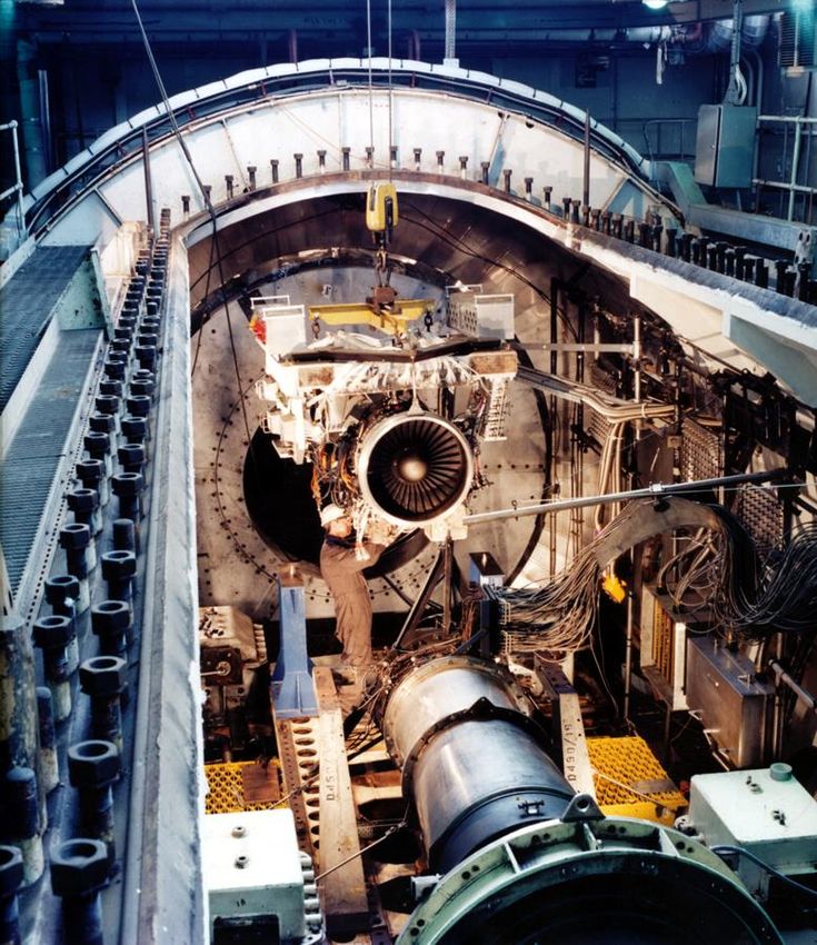
As engine powers increased, with commensurate increases in jet velocities and temperatures,
the environmental problems of noise pollution – particularly around large and busy airports –
became important and Pyestock set up the early noise reduction test facilities; the first anechoic
chamber was built in the early 1960s. The increasing demand for quieter aircraft stimulated more
research work, and as a result a larger test facility capable of undertaking large scale noise tests
on a variety of gas turbine components opened in the 1970s.
The new facility consisted of two main laboratories, fully independent of each other – the
Absorber Rig (1972) and the Anechoic Chamber (1974). The Anechoic Facility had a 10,000
cubic metre chamber for noise testing which reproduced environmental conditions comparable
to those in flight and permitted work to separately identify the source and direction of noise
wave phenomena. The building was principally intended for noise testing jets, turbines and
certain configurations of acoustically lined ducts (Figure 20).
Working with UK industry, significant advances were achieved in the understanding and the
reduction of engine noise which led to the Queen’s Award for Technological Achievement
being jointly awarded in 1990 to Propulsion Department RAE and the Design Engineering
Group, Rolls-Royce.
78You can also read