Actuation efficiency of nanosecond repetitively pulsed discharges for plasma-assisted swirl flames at pressures up to 3 bar - IOPscience
←
→
Page content transcription
If your browser does not render page correctly, please read the page content below
Journal of Physics D: Applied Physics

PAPER • OPEN ACCESS

Actuation efficiency of nanosecond repetitively pulsed discharges for
plasma-assisted swirl flames at pressures up to 3 bar
To cite this article: Francesco Di Sabatino et al 2021 J. Phys. D: Appl. Phys. 54 075208

View the article online for updates and enhancements.

                               This content was downloaded from IP address 46.4.80.155 on 18/01/2021 at 20:32
Journal of Physics D: Applied Physics
J. Phys. D: Appl. Phys. 54 (2021) 075208 (11pp) https://doi.org/10.1088/1361-6463/abc583
Actuation efficiency of nanosecond
repetitively pulsed discharges for
plasma-assisted swirl flames at
pressures up to 3 bar
Francesco Di Sabatino1, Thibault F Guiberti1, Jonas P Moeck2, William L Roberts1
and Deanna A Lacoste1
1
Clean Combustion Research Center, King Abdullah University of Science and Technology, Thuwal
23955-6900, Saudi Arabia
2
Norwegian University of Science and Technology, 7491 Trondheim, Norway
E-mail: deanna.lacoste@kaust.edu.sa
Received 26 August 2020, revised 12 October 2020
Accepted for publication 28 October 2020
Published 2 December 2020
Abstract
This study analyzes different strategies of plasma actuation of premixed swirl flames at
pressures up to 3 bar. A wide range of applied voltages and pulse repetition frequencies (PRF) is
considered, resulting in different combinations of nanosecond repetitively pulsed (NRP)
discharge regimes, NRP glow and NRP spark discharges. Electrical characterization of the
discharges is performed, measuring voltage and current, and deposited energy and power are
evaluated. The effectiveness of the plasma actuation is assessed through images of OH∗
chemiluminescence from the flame. From these images, the distance of the center of gravity of
the flame to the burner plate is evaluated, with and without plasma actuation. The results show
that strategies which involve a high percentage of NRP sparks are effective at improving flame
anchoring at atmospheric pressure, while they are detrimental at higher pressures. Therefore,
high applied voltage and low PRF are preferable at atmospheric pressure, while the opposite is
observed at elevated pressures. Moreover, it is found that a ratio of plasma power to thermal
power of the flame around 1% is the best compromise between a strong actuation of the flame
and a reasonable deposited electrical power. Explanations for these results are
proposed.
Keywords: flame stabilization, non-equilibrium plasma discharges, plasma-assisted combustion,
high-pressure combustion.
(Some figures may appear in colour only in the online journal)
1. Introduction
Improving combustion efficiency and reducing pollutant emis-
sions in combustion systems such as gas turbine engines are
major challenges that the scientific community is currently
facing. In this context, burning fuels in lean premixed con-
dition and at elevated pressure is a strategy widely utilized.
Original Content from this work may be used under the
terms of the Creative Commons Attribution 4.0 licence. Any
However, these burning conditions have limitations, such as
further distribution of this work must maintain attribution to the author(s) and unstable combustion and flame blow-off [1]. Finding ways to
the title of the work, journal citation and DOI. avoid or mitigate these phenomena in gas turbine combustors
1361-6463/21/075208+11$33.00 1 © 2020 The Author(s). Published by IOP Publishing Ltd Printed in the UK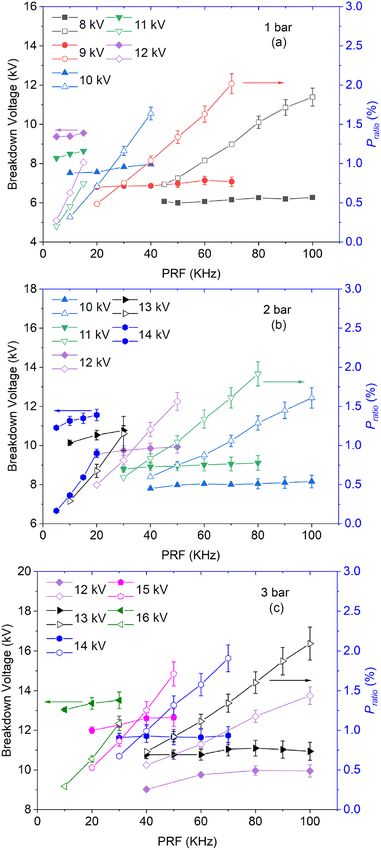
J. Phys. D: Appl. Phys. 54 (2021) 075208                                                                                  F Di Sabatino et al

or in high-pressure burners would be of interest for the design
of clean combustion systems.
    Non-thermal plasmas generated by nanosecond repetitively
pulsed (NRP) discharges have been utilized to improve the sta-
bility of various types of flames, including lean premixed swirl
flames that are widely used in gas turbine combustors [2–12].
However, the vast majority of these studies was carried out at
atmospheric pressure, with only two recent papers presenting
the effect of NRP discharges on flames at elevated pressures.
In [11], Kim and Cohen showed that the lean blow-off limit
of methane-air jet flames could be extended by NRP plasma
discharges at pressures up to 5 bar. Unfortunately, they found
that, with their plasma actuation strategy, the effectiveness of
plasma actuation on the flame was decreasing with increas-
ing pressure. As they did not provide any characterization of
the discharges, no conclusion on the efficiency of the plasma
actuation strategy could be drawn.
    In [12], Di Sabatino and Lacoste demonstrated that NRP
discharges were efficient in extending the blow-off limit of
lean premixed swirl flames at pressures up to 5 bar. They found
that the effectiveness of plasma actuation remained almost
constant with increasing pressure. Moreover, the plasma dis-
charges were electrically characterized, highlighting that actu-
ation with NRP discharges in the glow regime, known to pro-
mote the chemical impact of the plasma, became more efficient
than actuation with NRP discharges in the spark regime, with
strong thermal and chemical impact, for pressures above 2 bar.
This result was not explained. Even though these two studies           Figure 1. Schematic of the PACCI burner with insert of a single
[11, 12] showed promising results for plasma actuation at elev-        shot OH∗ chemiluminescence image of the flame during actuation
                                                                       by NRP sparks at 1 bar. All dimensions in millimeters.
ated pressures, they did not provide extensive parametric ana-
lysis, that could, for example, explain the discrepancy in their
conclusions concerning the effectiveness of plasma actuation
by NRP discharges at elevated pressure. This is the purpose of            A schematic of the PACCI burner is presented in figure 1.
the present study.                                                     The mixture of methane and air, controlled by mass flow
    The two main objectives of this study are (1) to compare           controllers (Brooks SLA58 series), is injected in a plenum,
different plasma actuation settings on the anchoring of lean           120-mm long. The accuracy and precision of the mass flow
premixed swirl flames at pressures up to 3 bar, and (2) to             controllers are around 1% of their actual values. Downstream
suggest effective plasma actuation strategies using NRP dis-           the plenum, the mixture flows through a honeycomb and a
charges for flames at elevated pressure.                               perforated plate before entering a radial swirler with a meas-
                                                                       ured swirl number of 0.4. The mixture is injected in the com-
                                                                       bustion section through an injection tube of 18 mm diameter.
2. Experimental setup and methodology                                  A stainless steel rod of 2.5 mm diameter is installed at the
                                                                       center of the injection tube. This rod serves as the anode
In this section, the experimental setup and diagnostics util-          (positive high-voltage, +HV in figure 1) for the generation of
ized are briefly presented. Then, the experimental conditions          plasma discharges, while the tip of the burner plate surround-
investigated are summarized. Finally, the methodology fol-             ing the injection tube serves as the cathode (negative high-
lowed to collect and analyze the data is detailed.                     voltage, -HV in figure 1). The injection tube is protected by
                                                                       a layer of ceramic material to avoid discharges in unwanted
                                                                       locations. The swirl flame is stabilized in the combustion
                                                                       section, confined by a 100 mm long and 70 mm diameter
2.1. PACCI burner and HPCD
                                                                       quartz tube.
The experimental setup comprises a swirl burner equipped                  The NRP discharges are generated between the stainless
with a system to generate plasma discharges, referred to as the        steel rod and the inner rim of the burner plate, separated
plasma-assisted control of combustion instabilities (PACCI)            by a gap of 7.75 mm, by applying 20 ns duration high-
burner. A detailed description of the PACCI burner is presen-          voltage pulses, at various pulse repetition frequencies (PRF).
ted in [13]. The burner is installed in a high-pressure combus-        In-house-designed high-voltage connections are utilized to
tion duct (HPCD). A detailed description of the HPCD can be            link the positive and negative outputs of the plasma generator
found in [14, 15].                                                     (FID FPD 25-100MC2), located outside of the HPCD, to the

                                                                   2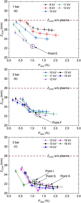
J. Phys. D: Appl. Phys. 54 (2021) 075208 F Di Sabatino et al
PACCI burner. These connections ensure that the high voltage
needed to generate the plasma discharges is safely delivered to
the anode and cathode of the burner. Except for the electrodes,
all other metallic parts of the PACCI burner are grounded.
The PACCI burner is installed in the HPCD, a large cyl-
indrical vessel of 0.41 m diameter, equipped with multiple
ports and optical windows. It can sustain pressures up to
45 bar; however, the maximum pressure used in this study is
3 bar. The pressure is regulated by a back pressure valve, loc-
ated about 3 m downstream of the PACCI burner. The HPCD
is grounded.
2.2. Diagnostics
In this study, the NRP discharges are electrically character-
ized, and the effect of plasma actuation on the flame is visually
assessed.
During plasma actuation of the flame, the applied voltage
is measured with voltage probes (Tektronix P6015A) on the
positive and negative high-voltage connections, outside of the
HPCD. The current is also measured outside of the HPCD,
with a current probe (Pearson Current Monitor, Model 6585)
on the ground cable. An oscilloscope (Agilent Technologies
Infiniium 2.5 GHz) is utilized to simultaneously record the two
voltage and the current signals.
Images of the chemiluminescence of excited hydroxyl rad-
icals (OH∗ ) from the flame are collected with a high-speed
CMOS camera (Lavision HSS8) equipped with an intensifier
(Lavision IRO), a UV lens (105 mm F/5.6 Coastal Optics),
and a 40-nm bandpass filter centered at 310 nm (Lavision
1108 760). These images are utilized to assess the effect of
NRP plasma discharges on the average position of the flame.
2.3. Experimental conditions
Three different operating pressures, Pamb , are considered in
this study: 1, 2, and 3 bar. The average bulk flow velocity,
V̄bulk , at the exit of the injection tube is maintained constant
at 6.8 m s−1 , for all the conditions analyzed. The equivalence
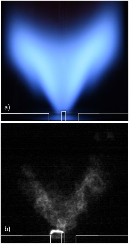
ratio of the mixture, ϕ, is slightly modified to keep a similar Figure 2. (a) Photograph of the methane–air swirl flame at 1 bar
flame shape when the pressure is increased. A photograph of (5 s exposure time). (b) OH∗ -chemiluminescence image of the same
flame with NRP spark discharges at 10 kHz and 12 kV (90 µs
the methane-air swirl flame at 1 bar is presented in figure 2(a).
exposure time, synchronized in-between two high-voltage pulses).
A summary of the combustion conditions investigated is White lines highlight the burner and rod contours.
reported in table 1. The thermal power of the flame is indic-
ated by Pflame , and Re is the bulk Reynolds number evaluated
at the exit of the injection tube. The distances of the center
2.4. Methodology
of gravity of the flame from the burner plate, ZCOG , are also
reported. They correspond to conditions without plasma actu- The characterization of the plasma discharges and the quanti-
ation. Since V̄bulk is kept constant when the operating pressure fication of their effect on the average flame position are carried
is increased, Pflame and Re increase with increasing pressure. out following the procedure detailed here.
For example, at 1 bar, Pflame = 4 kW and Re = 7800, while at After the flame is ignited by a laser-generated spark, the
3 bar Pflame = 11.5 kW and Re = 23,400. burner is run for 15 min to ensure thermal equilibrium.
During plasma actuation, the pulse duration is kept con- The plasma actuation is then initiated, for a given applied
stant (about 20 ns). The applied voltage and PRF are the two voltage and PRF. After steady-state is reached (after 10 s
parameters investigated in this study, for the three pressures of plasma actuation), the temporal evolution of the voltage
considered. The range of applied voltages considered is 8– and current signals is measured for 500 pulses. The applied
16 kV, while the range of PRFs is 5–100 kHz. voltage measured on the cathode is inverted and added to
3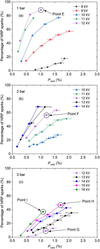
J. Phys. D: Appl. Phys. 54 (2021) 075208                                                                                                  F Di Sabatino et al

         Table 1. Summary of the experimental conditions.                                        COG w/ plasma             COG w/o plasma
                                                  −1
Pamb (bar)     ϕ     Pflame (kW) V̄bulk (m s           )    Re      ZCOG (mm)

                                                                                                                                                            Normalized OH* Intensity [-]
                                                                                                                                                      1.0
1            0.67         4.0               6.8              7800     28.1
2            0.65         7.9               6.8            15,600     27.7                                                                            0.8
3            0.63        11.5               6.8            23,400     27.8
                                                                                                                                                      0.6

                                                                                                                                                      0.4
the applied voltage measured on the anode. The resulting
waveform is synchronized with the total current waveform.                                                                            ZCOG             0.2
                                                                                                                      z

                                                                                                                                             10 mm
By multiplying the applied voltage and current, the electrical                               Quartz                                                   0
energy deposited by each pulse is determined. The depos-                                     Ceramic
ited power is evaluated by multiplying the PRF by the aver-                                  Stainless steel
age energy deposited over 500 pulses. This procedure is fol-                                 NRP discharge                      r
lowed for each condition of pressure, applied voltage, and PRF
investigated.                                                                          -HV                                +HV
    The effect of the plasma actuation on the average flame
position is quantified by utilizing the images of OH∗ chemilu-                         Figure 3. Examples of average OH∗ chemiluminescence images of
minescence. These images are collected after reaching steady                           a flame with (left) and without (right) plasma actuation, at 1 bar.
                                                                                       Plasma actuation is generated by pulses of 12 kV and 10 kHz. The
state, as defined in the previous paragraph. The camera is syn-                        center of gravity (COG) of the two flames as well as ZCOG are
chronized to take images only in-between pulses. However,                              highlighted. The ZCOG without and with plasma actuation are 28 and
the OH∗ filaments generated by the discharges emit for a dur-                          24 mm, respectively.
ation longer than the delay between the pulses (10–200 µs,
depending on the PRF). They are so intense compared to the
naturally occurring OH∗ chemiluminescence of the flame that                            3. Results and discussion
no information could be extracted from the base of the flame,
as shown in figure 2(b). The field of view of the camera is                            In this section, first the electrical characterization of the NRP
then chosen to avoid direct imaging of the plasma filaments                            discharges is presented. Then, the effect of plasma actuation
that could saturate and damage the camera. Series of 1000                              on the average flame position at different operating pressures
images are collected for each experimental condition, with and                         is shown and analyzed. Finally, the plasma actuation strategies
without plasma actuation, for each combination of pressure,                            at different pressures are discussed.
applied voltage, and PRF. Since different values of PRF are
considered, the acquisition frequency and the exposure time                            3.1. Electrical properties of the plasma discharges
of the camera are adjusted accordingly. Moreover, each image
is corrected for non-linearities of the camera. Averaging these                        Depending on the applied voltage and PRF, two discharge
1000 images, a mean image of the flame is obtained. It is veri-                        regimes can be obtained, namely, NRP glow and the NRP
fied that, even if the total averaging time differs if the PRF                         spark discharges, as defined in [16, 17]. The NRP glow dis-
is modified, the average flame images of all the experimental                          charges mainly have a chemical impact on the flame [18],
conditions are statistically converged. Examples of average                            while NRP spark discharges influence the flame hydrodynam-
flame images, with and without plasma actuation, are repor-                            ically, thermally, and chemically [19–21]. Examples of the
ted in figure 3.                                                                       temporal evolution of the voltage, total current, and corres-
    The position of the center of gravity (COG) of the flames is                       ponding deposited energy are presented in figure 4 for NRP
estimated from these average images. In the (r, z) plane, such                         glow discharges (a) and NRP spark discharges (b). These
as defined in figure 3, the coordinates of the COG, RCOG and                           waveforms are measured in a flame at 1 bar, for a setting of
ZCOG , are obtained from:                                                              the plasma generator at 8 kV and a PRF of 50 kHz.
                                                                                          First, it is interesting to note that for a given setting of the
                     ∑                           ∑                                     plasma actuation, both NRP glow discharges and NRP spark
                       Ii · ri                     Ii · zi                             discharges may be observed, with a similar breakdown voltage
               RCOG = ∑ ,                  ZCOG = ∑ ,                        (1)
                         Ii                          Ii                                of about 6 kV (peak voltage in figures 4(a) and (b). This is
                                                                                       probably due to the highly complex gaseous media in the inter-
                                                                                       electrode area, with a time-varying combination of turbulent
where I i is the intensity of the ith pixel of the image, and ri and                   fresh mixture, flame front, and burned gases. Depending on
zi are its coordinates. The distance from the COG to the burner                        the local gas composition at breakdown, the discharges can be
plate in the z-direction (ZCOG ) is utilized as a parameter high-                      either in the glow or spark regime. Note that as the instant-
lighting the effect of plasma actuation on the average flame                           aneous energy is calculated utilizing the total current, it is
position. A detailed analysis of the effect of plasma actuation                        not always increasing with time. Fluctuations of instantan-
on the ZCOG is presented in the next section.                                          eous energy are induced by the charge and discharge of stray

                                                                                   4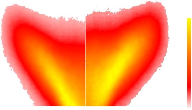
J. Phys. D: Appl. Phys. 54 (2021) 075208                                                                                       F Di Sabatino et al

                                                                          conditions for which no discharge was obtained. For all cases,
                                                                          it is below 5% of the energy obtained for the NRP glow dis-
                                                                          charges. Knowing the PRF and the average deposited energy
                                                                          for the 500 pulses measured, it is possible to determine the
                                                                          average power of the plasma discharges, Pplasma , for a given
                                                                          condition. The ratio of Pplasma and thermal power released by
                                                                          the flame, Pflame , defines the power ratio, Pratio , that is utilized
                                                                          in the analysis of the results in the following sections.
                                                                              Another quantity of interest extracted from the electrical
                                                                          characterization of the discharges is the percentage of NRP
                                                                          sparks for a given condition. Figure 5 presents an example of
                                                                          distribution of number of pulses as a function of the energy
                                                                          deposited for 500 NRP discharges produced in a flame at 1
                                                                          bar, for 11 kV applied voltage and 10 kHz PRF. The bi-modal
                                                                          distribution of the pulses allows for a clear distinction between
                                                                          the two discharge regimes.

                                                                          3.2. Effect of plasma power and applied voltage on the flame
                                                                          anchoring

                                                                          As shown in figure 3, NRP discharges affect the position of the
                                                                          flame. Specifically, the COG of the flame moves towards the
                                                                          burner plate during plasma actuation, and the distance between
                                                                          the COG and the burner, ZCOG , is reduced. This anchoring
                                                                          effect is a direct indicator of the plasma actuation because
Figure 4. Examples of the temporal evolution of the voltage,              it results from the same plasma effect on the flame as that
current and corresponding energy, obtained for NRP glow                   responsible for reducing the response of a flame to acoustic
discharges (a) and NRP spark discharges (b), generated by pulses of
8 kV applied at 50 kHz, in a flame at 1 bar.                              perturbations [13], or to promote the stabilization of flames
                                                                          close to blow-off [3, 4, 7–10, 12]. Thus, it is interesting to ana-
                                                                          lyze how ZCOG evolves during plasma actuation with different
                                                                          combinations of discharge parameters, at different operating
                                                                          pressures.
                                                                              Figure 6 presents the evolution of ZCOG as a function of
                                                                          the power ratio, Pratio , at 1 (a), 2 (b), and 3 bar (c). Since
                                                                          for any plasma actuation, a combination of NRP glows and
                                                                          sparks is obtained, the average deposited energy utilized to cal-
                                                                          culate Pratio is evaluated considering both discharge regimes.
                                                                          At all pressures, without plasma actuation, ZCOG ≈ 28 mm
                                                                          (see table 1) and when NRP discharges are applied, ZCOG
                                                                          decreases. The value of ZCOG without plasma actuation is
                                                                          almost constant with increasing the pressure because the equi-
                                                                          valence ratio has been adjusted to maintain a similar flame
                                                                          shape for all pressures, as explained in section 2.3. For a given
                                                                          pressure and applied voltage, Pratio is changed by adjusting
                                                                          the PRF, between 5 and 100 kHz (see section 3.5). Note that
                                                                          for the three pressures considered, different ranges of applied
                                                                          voltage are investigated. These ranges result from two lim-
Figure 5. Number of pulses as a function of the energy deposited
for 500 NRP discharges produced in a flame at 1 bar for 11 kV
                                                                          iting conditions: achieving NRP spark discharges and main-
applied voltage and a PRF of 10 kHz.                                      taining the integrity of the burner. For example, at 2 bar, for
                                                                          an applied voltage of 9 kV, no NRP spark discharges can be
                                                                          observed, while for an applied voltage of 15 kV, the probabil-
capacitance of the electrical circuit. After about 0.5 µs, the            ity for the flame to flash-back into the injection tube becomes
instantaneous energy remains constant, and its value corres-              very high. Moreover, the strong NRP sparks produced would
ponds to the energy deposited by a discharge in the gap. In               quickly damage the electrodes.
this example, the NRP spark deposits 1.5 mJ, while the NRP                    For the three pressures studied, at constant applied voltage,
glow only deposits 0.9 mJ. The error induced by using the total           ZCOG generally decreases with increasing Pratio . However, for
current instead of the conductive current has been evaluated by           a power ratio larger than 1%, this decrease becomes mar-
calculating the energy using voltage and current waveforms for            ginal. It is interesting to note that regardless of the pressure,

                                                                      5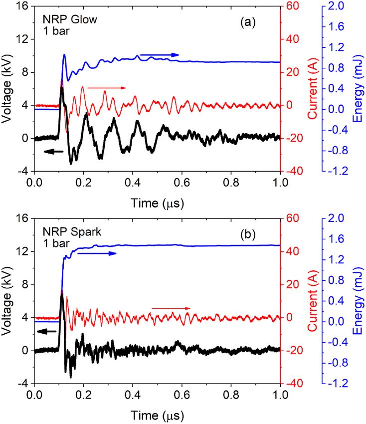
J. Phys. D: Appl. Phys. 54 (2021) 075208                                                                                            F Di Sabatino et al

                                                                                 ZCOG reaches a similar absolute minimum value of 20–22 mm
                                                                                 (at 1 bar, ZCOG minimum is equal to 22.3 mm, at 2 bar, it
                                                                                 is equal to 22.0 mm, and at 3 bar, it is equal to 20.5 mm).
                                                                                 This distance corresponds to fully anchored flames. As the
                                                                                 shape of the flame is the same at all pressures (thanks to
                                                                                 adjustments in the equivalence ratio), ZCOG for the fully
                                                                                 attached flames takes the same value at all pressures. A
                                                                                 smaller value in ZCOG would correspond to the beginning of
                                                                                 a flash-back of the flame in the injection tube. Moreover,
                                                                                 saturation of the plasma effect on the flame might affect
                                                                                 the absolute minimum value of ZCOG . Additional experi-
                                                                                 ments should be carried out to highlight possible saturation
                                                                                 mechanisms in the flame response to plasma forcing. There
                                                                                 are two exceptions for the general trend just described: the
                                                                                 cases of flame actuation at 3 bar with 15 and 16 kV of
                                                                                 applied voltage (pink pentagon and green triangles in fig-
                                                                                 ure 6(c), respectively). In these two cases, ZCOG first decreases
                                                                                 with increasing Pratio , and then increases. An increase in
                                                                                 ZCOG is an indicator that the flame is less anchored on the
                                                                                 burner, i.e., the NRP discharges are less efficient in stabilizing
                                                                                 the flame.
                                                                                    Finally, for a given Pratio , at 1 bar, the NRP discharges have
                                                                                 an increasing effect on the anchoring of the flame by increas-
                                                                                 ing the applied voltage. For example, for Pratio = 1%, at 8 kV
                                                                                 (black squares in figure 6(a), ZCOG = 26.5 mm, while at 12 kV
                                                                                 (violet diamonds in figure 6(a), ZCOG = 22.3 mm. However, at
                                                                                 2 and 3 bar, for a given Pratio , the effect of applied voltage is
                                                                                 less pronounced.
                                                                                    In summary, at all pressures investigated, NRP discharges
                                                                                 have an anchoring effect on the swirl flames. Furthermore,
                                                                                 increasing the ratio of plasma power to flame thermal power,
                                                                                 Pratio , generally increases the effect of the plasma actuation.
                                                                                 However, Pratio is not the only parameter controlling the effect-
                                                                                 iveness of plasma actuation. At atmospheric pressure, for a
                                                                                 constant Pratio , an increase in applied voltage increases the
                                                                                 effect of the plasma, while at 3 bar, an increase in applied
                                                                                 voltage can have a reverse effect on the flame anchoring. The
                                                                                 effect of applied voltage on the plasma actuation efficiency is
                                                                                 discussed in the next section.

                                                                                 3.3. Effect of applied voltage on the actuation efficiency

                                                                                 At a given pressure, an increase in applied voltage increases
                                                                                 both the percentage of NRP spark discharges versus NRP
                                                                                 glow discharges and the average energy per pulse. Therefore,
                                                                                 to obtain a constant Pratio , the PRF has to be decreased and,
                                                                                 consequently, the delay between discharges increases. This
                                                                                 increase in stronger and sparser discharges could explain the
                                                                                 results on the effect of the applied voltage, positive or negative,
                                                                                 on the flame anchoring presented in figure 6.
                                                                                    Figure 7 presents the percentage of NRP sparks obtained
                                                                                 for 500 discharges as a function of Pratio and applied voltage,
Figure 6. Distance between the burner plate and the center of                    for the three pressures considered. For a given Pratio , the range
gravity of the flame, ZCOG , as a function of the plasma to flame                of percentages of NRP spark discharges obtained for the dif-
power ratio, Pratio , at 1 (a), 2 (b), and 3 bar (c) for different applied
voltages. The error bars on Pratio represent the standard deviation of
                                                                                 ferent values of applied voltage is larger at 1 bar than at higher
the measurements. The error bars on ZCOG represent the uncertainty               pressures. For example, for Pratio = 1%, the percentage of NRP
due to the spatial resolution.                                                   sparks ranges from 5% at 8 kV to 90% at 12 kV, while at 2 bar,

                                                                             6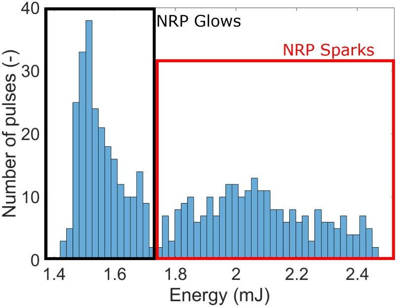
J. Phys. D: Appl. Phys. 54 (2021) 075208                                                                                         F Di Sabatino et al

                                                                                it ranges from from 15% at 10 kV to 70% at 13 kV, and at 3 bar,
                                                                                from 5% at 12 kV to 40% at 16 kV.
                                                                                    At 1 bar, for Pratio = 1%, the most efficient plasma actu-
                                                                                ation is obtained for 12 kV (Point E in figures 6(a) and 7(a)).
                                                                                This actuation is obtained for 90% of NRP sparks. For an
                                                                                actuation with mainly NRP glow discharges, for example at
                                                                                8 kV with 5% of NRP sparks, the plasma effect on the flame
                                                                                anchoring becomes weaker; less than a 2 mm decrease in ZCOG
                                                                                is observed, even though Pratio is still 1%. This result sug-
                                                                                gests that at atmospheric pressure, the thermal impact of NRP
                                                                                sparks plays a key role in the flame anchoring, while the chem-
                                                                                ical effect of NRP glow discharges is less effective. This is in
                                                                                agreement with previous studies [22, 23], showing that a com-
                                                                                bined thermal and chemical action has a stronger effect on the
                                                                                combustion process than a purely chemical one.
                                                                                    At 2 bar, for Pratio = 1%, the efficiency of plasma actuation
                                                                                on the flame anchoring is very similar for a large range of
                                                                                NRP spark percentages, from 15% to 70% (see figures 6(b)
                                                                                and 7(b)). This result suggests that at 2 bar, the flame is
                                                                                not sensitive to the plasma regime and NRP glow discharges
                                                                                become as effective as NRP sparks. This could be explained
                                                                                by either a stronger chemical impact on combustion at elev-
                                                                                ated pressure or an increase of the thermal impact associ-
                                                                                ated with NRP glow discharges. Indeed, to maintain a given
                                                                                Pratio while increasing pressure, it is necessary to increase the
                                                                                PRF to promote NRP glow discharges instead of NRP sparks
                                                                                (see section 3.5 and figure 9). Recently, Adams et al [24]
                                                                                showed that an increase in PRF could significantly increase the
                                                                                thermal impact of similar discharges in air. Further investiga-
                                                                                tion is necessary to conclude. Note that this change in effect-
                                                                                iveness between NRP glow and NRP spark discharges at 2 bar
                                                                                has recently been reported in [12] for enhancement of the lean
                                                                                blow-off limit.
                                                                                    At 3 bar, similar conclusions as at 2 bar can be drawn,
                                                                                except for points H and I (see figures 6(c) and 7(c)), obtained
                                                                                for 15 and 16 kV, for which a larger percentage of NRP spark
                                                                                discharges has a negative effect on the flame anchoring. This
                                                                                non-monotonic trend may be explained by considering the
                                                                                strength of the NRP spark discharges generated at elevated
                                                                                pressure.
                                                                                    During the experimental campaign, for 15 and 16 kV
                                                                                applied voltage, strong disturbances of the base of the flame
                                                                                could be observed. Visually, these disturbances correlated
                                                                                with strong discharges (i.e. intense light emission of the dis-
                                                                                charge filament). Due to the sudden thermal expansion of the
                                                                                gas heated by the discharges, shock waves are produced by
                                                                                NRP spark discharges [20]. These shock waves lose energy
                                                                                rapidly and become acoustic waves, but in the cases of 15 and
                                                                                16 kV, they may be strong enough to disturb the anchoring of
                                                                                the flame on the central rod. Indeed, the discharges are gener-
                                                                                ated at the close vicinity of the inner recirculation zone, which
                                                                                is known to be a key area for swirl flame stabilization (see for
Figure 7. Percentage of NRP sparks for 500 pulses as a function of              example [25, 26]). Note that these disturbances of the flame
power ratio at 1 (a), 2 (b), and 3 bar (c) for different applied voltage.       base were not observed regularly but more like exceptional
The error bars represent the standard deviation of the measurement.             events, i.e. a few times per minute.

                                                                            7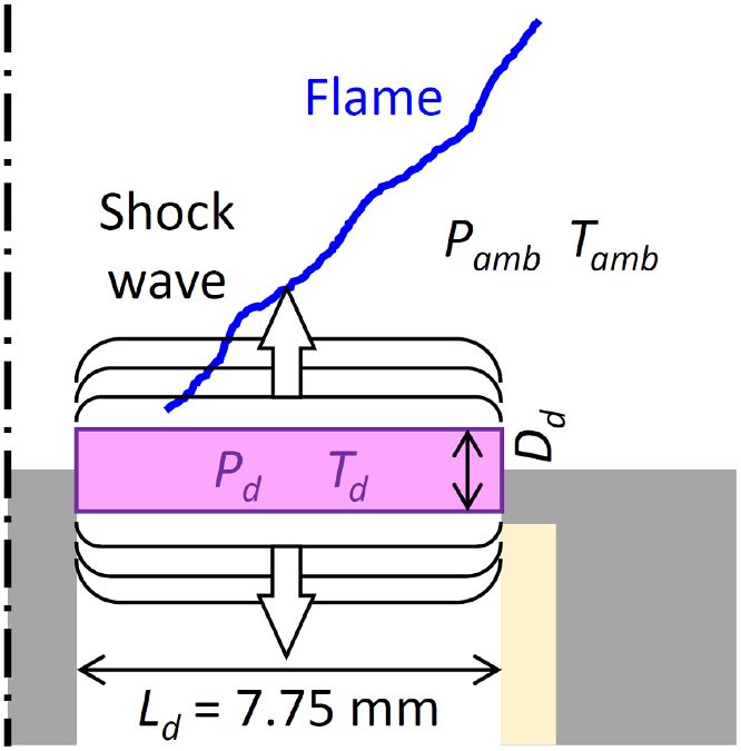
J. Phys. D: Appl. Phys. 54 (2021) 075208                                                                                          F Di Sabatino et al

Figure 8. Schematic of the NRP discharge model in the
inter-electrode gap. The scale of the discharge is exaggerated to help
visualization.

3.4. Hydrodynamic effect of the plasma actuation

In order to verify if at 3 bar for 15 and 16 kV applied voltage,
the shock waves produced by NRP sparks could be stronger
than for the other conditions, a simple model is proposed here.
The strength of the shock wave following an NRP spark, Sshock ,
can be defined as the ratio between the change in pressure
across the shock over the ambient pressure, Pamb [27]:

                                    Pd − Pamb
                         Sshock =             ,                   (2)
                                      Pamb

where Pd is the pressure in the discharge channel at the end of
an NRP spark, that has to be determined. Figure 8 presents a
schematic of the situation considered here.
    During an NRP spark discharge, the energy is deposited in
a very short time and Pd can be calculated considering heat-
ing at constant volume of the gas in the discharge channel.
For the conditions of this study, the fraction of total energy
deposited by the discharges that goes into ultra-fast heating,
Ethermal , is assumed to be 20% of the total deposited energy,
as for example in [19]. Only NRP spark discharges are con-
sidered in this model. Therefore, Ethermal is evaluated from
the average energy per pulse deposited by NRP spark dis-
charges at each condition analyzed. The discharge channel                    Figure 9. Breakdown voltage (solid symbols) and power ratio
is modeled as a cylinder of length Ld equal to the electrode                 (empty symbols) as a function of PRF at 1 (a), 2 (b), and 3 bar (c)
gap distance, i.e., 7.75 mm, and of diameter Dd . The dia-                   for different applied voltages. The error bars represent the standard
meter of an NRP spark discharge depends on multiple para-                    deviation of the measurements.
meters, including gap distance, gas composition, pressure,
and temperature. For a simple model, as the gap distance,
gas composition, and temperature do not change much for                      where A and B are constants. Assuming discharges in a
all conditions, Dd is considered to be only a function of the                methane-air mixture at ambient temperature, Tamb = 300 K, A
pressure:                                                                    and B are determined using experimental results from [20, 28].
                                                                             In [28], Xu et al showed that for pressures in the range of
                           Dd = AP− 1
                                  amb + B,                        (3)        1–5 bar, and for energies per pulse in the range of 1.8–9 mJ,

                                                                         8
J. Phys. D: Appl. Phys. 54 (2021) 075208 F Di Sabatino et al
NRP sparks in lean propane–air mixtures and in air have sim- pulse duration, the applied voltage, the pulse repetition fre-
ilar diameters. Here, it is assumed that NRP discharges in quency, and the location of the discharges in the combus-
lean methane–air mixtures have a diameter similar to that of tion system. In this study, only the applied voltage and the
NRP sparks in lean propane-air mixtures. Furthermore, meas- PRF have been varied. Their effects on the plasma actuation
urements by a thermocouple in the injection tube, with flame strategies are discussed here.
but without plasma actuation, confirmed that, at atmospheric As discussed in section 3.2, applying a plasma power
pressure, the average temperature in the inter-electrode area is around 1% of the thermal power released by the flame is a good
close to ambient. Depending on the conditions, a maximum compromise between the deposited power and an efficient
average temperature of 350 K was measured. For a pressure plasma actuation by NRP discharges at pressures between 1
in bar and a discharge diameter in millimeter, A = 0.21 mm and 3 bar. For Pratio > 1%, any additional increase in plasma
bar and B = 0.24 mm. Thus, Dd decreases from 0.45 mm at 1 power will have a marginal effect on the flame anchoring.
bar to 0.345 mm at 2 bar, and 0.31 mm at 3 bar. Under these Moreover, the percentage of NRP sparks impacts the effect-
assumptions, and assuming ideal gas conditions, Pd is calcu- iveness of plasma actuation. For a given PRF, an increase of
lated from: the applied voltage will increase the percentage of NRP sparks
versus NRP glow discharges. Similarly, for a given Pratio , an
Ethermal
Td m cv + Tamb increase in applied voltage will increase the percentage of
Pd = × Pamb = × Pamb , (4)
Tamb Tamb NRP sparks (see figure 7). Therefore, there is value in utilizing
high applied voltage.
where cv is the specific heat at constant volume of the However, higher applied voltages are prone to generate
methane–air mixture at Tamb , and m is the mass of gas in the high electro-magnetic interference (EMI). For this issue, the
discharge volume. applied voltage is an important factor and it should be min-
Table 2 summarizes the values of Dd and Sshock obtained imized. The minimal voltage that must be applied to obtain
for six data points of interest. Points E, F, and G feature the a plasma actuation is the breakdown voltage. Therefore, it is
same applied voltage (12 kV) and Pratio (≈1%) for ambient also important to determine how the applied voltage and the
pressures of 1, 2, and 3 bar, respectively. While Ethermal slightly PRF will affect the breakdown voltage.
increases with pressure, the strength of the shock Sshock slightly The breakdown voltage and the power ratio measured as a
decreases from 1.7 to 1.4, and the effect on the flame anchor- function of the PRF are reported in figure 9, for all applied
ing is similar for these three conditions with ZCOG ≈ 22.5 mm voltages at 1 (a), 2 (b), and 3 bar (c). For all experimental
(see figure 6). conditions, at constant applied voltage, the breakdown voltage
Points H and I correspond to the strongest plasma actuation is practically constant with increasing PRF. This means that
obtained with 15 and 16 kV for a flame at 3 bar (see figure 6). the synergistic effect of multiple pulses that may be reached
For these two points, the shocks generated by the NRP spark for high PRF does not have a strong influence on the break-
discharges are significantly stronger than for lower applied down voltage, for the experimental conditions of this study.
voltage, with Sshock = 2.4 and Sshock = 2.6, respectively. The On the other hand, the breakdown voltage increases with the
shock waves generated by the NRP sparks for these conditions applied voltage. This is induced by the sharp rise time of the
may be powerful enough to disturb the base of the flame and voltage pulse, within 2 ns. As this rise time is constant, the tem-
to have a negative impact on flame anchoring. poral gradient of the voltage increases with the applied voltage
The simple model used here does not account for the full (for example, from 4 kV/ns at 8 kV to 6 kV/ns at 12 kV). For
complexity of the experiments. However, it suggests that at all applied voltages, the breakdown voltage is always lower
elevated pressures, the ultra-fast heating associated with NRP than the applied voltage. Therefore, the breakdown occurs dur-
spark discharges may have a negative impact on flame actu- ing this sharp gradient. This difference in gradient impacts the
ation. More detailed modeling, including the gas mixture com- breakdown process and, as expected, a higher gradient induces
plexity in the inter-electrode area, multi-dimensional effects a higher breakdown voltage [29]. Finally, at all pressures, at
such as bending of the spark discharge due to the turbulent constant applied voltage, Pratio increases with PRF, and at con-
swirling flow and shock wave-induced flow structures, the stant PRF, Pratio increases with the applied voltage.
effect of the experimental conditions on the fraction of total At 1 bar, for Pratio = 1%, the most efficient plasma actu-
energy that goes into ultra-fast heating, and a more precise ation is obtained for the highest applied voltage (12 kV) and a
evaluation of the discharge diameters should be performed to low PRF (15 kHz), as shown in figure 6. Unfortunately, this
confirm this result. setting gives the highest breakdown voltage (9 kV), i.e. the
worst condition for EMI. Consequently, the selection of PRF
and applied voltage will be a compromise between the most
3.5. Plasma actuation strategies
efficient plasma actuation and the control of EMI.
To compare the different plasma actuation strategies using At 2 bar, for Pratio = 1%, the efficiency of plasma actu-
NRP discharges, it is important to determine the most rel- ation is not very sensitive to the applied voltage (see figure 6).
evant parameters. At the combustion system level, the actu- Therefore, as the lowest breakdown voltage is obtained for low
ation efficiency is key, but the robustness and the integration applied voltage, the optimized plasma actuation strategy will
of the plasma actuator are also important. To optimize all these be to promote a high PRF and a low applied voltage. In this
aspects, actuation by NRP discharges offers four levers: the study, the best plasma actuation strategy is to apply 10 kV
9J. Phys. D: Appl. Phys. 54 (2021) 075208 F Di Sabatino et al
Table 2. Summary of calculated discharge diameter, Dd , and strength of the shock, Sshock , for five conditions highlighted in figures 6 and 7.
Point Vapplied (kV) PRF (kHz) Ethermal (mJ) Pamb (bar) Dd (mm) Sshock
E 12 15 0.54 1 0.450 1.7
F 12 40 0.58 2 0.345 1.6
G 12 80 0.61 3 0.310 1.4
H 15 50 1.06 3 0.310 2.4
I 16 30 1.16 3 0.310 2.6
pulses at 70 kHz. The flame actuation will then be optimal applied voltages. Strong shock waves generated by the NRP
(with a Pratio = 1% and a flame fully anchored), and the break- sparks obtained for these conditions may be responsible for
down voltage will be minimal (8 kV). Note that the best plasma the flame destabilization, and the limited benefit on flame
actuation strategy at 2 bar will be achieved for an applied anchoring.
voltage lower than the applied voltage necessary to obtain the • While for swirl flames at atmospheric pressure the best
most effective plasma actuation at 1 bar (12 kV). strategy for plasma actuation is to increase the applied
Finally, at 3 bar, conclusions are similar as at 2 bar: the voltage and control the plasma power by setting a low pulse
best plasma actuation strategy will be to choose pulses of low repetition frequency, at 2 and 3 bar, it is more efficient to
applied voltage at high repetition frequency. In this study, this choose the lowest applied voltage required for breakdown
corresponds to 12-kV applied voltage and a PRF of about and to adjust the plasma power by increasing the pulse repe-
75 kHz, for which the breakdown voltage will be as low as tition frequency. This result is promising for plasma actu-
10 kV, and the flame will be fully anchored for Pratio = 1%. ators targeting high-pressure combustion systems such as
These results at pressures up to 3 bar show that high val- gas turbine engines.
ues of applied/breakdown voltage are not always necessary for
an efficient plasma actuation strategy, while the repetition fre-
quency of the pulses may be a key factor for flame actuation Acknowledgments
at elevated pressure.
This work is funded by the King Abdullah University of Sci-
ence and Technology, the Deutsche Forschungsgemeinsch-
4. Conclusion aft, and the Agence Nationale de la Recherche, through the
GECCO project.
The efficiency of plasma actuation of premixed swirl flames
by NRP discharges has been investigated at pressure up to 3
bar. Various combinations of applied voltage and PRF have ORCID iDs
been investigated. Images of OH∗ chemiluminescence from
the flames have been collected and analyzed to assess the effect Francesco Di Sabatino https://orcid.org/0000-0003-0038-
of NRP plasma discharges on the average position of the center 1395
of gravity of the flame. The main findings are: Deanna A Lacoste https://orcid.org/0000-0002-4160-4762
• For pressures between 1 and 3 bar, the most efficient plasma
References
actuation of the flame is obtained for a ratio between the
plasma power deposited by NRP discharges and the thermal [1] Lieuwen T and Yang V eds 2005 Combustion Instabilities in
power released by the flame of about 1%. Above 1%, Gas Turbine Engines (Progress in Astronautics and
adding more plasma power has only a marginal effect on Aeronautics (AIAA, Inc.) vol 210
flame anchoring. [2] Mintoussov E, Pancheshnyi S and Starikovskii A 2004 Proc.
• At atmospheric pressure, for a given plasma power, the 42nd AIAA ASM, Reno, Nevada AIAA 2004–1013
[3] Choi W, Neumeier Y and Jagoda J 2004 Proc. 42nd AIAA
plasma actuation is more efficient for elevated applied ASM, Reno, Nevada AIAA-2004-982
voltages, i.e. when the percentage of NRP sparks versus [4] Starikovskaia S M, Kosarev I N, Krasnochub A V, Mintoussov
NRP glow discharges is high. E I and Starikovskii A Y 2005 Proc. 43rd AIAA ASM, Reno,
• At 2 and 3 bar, the discharge regime, controlled by the Nevada AIAA 2005–1195
applied voltage, had little influence on flame anchoring, [5] Kim W, Mungal M and Cappelli M 2005 Proc. 43rd AIAA
ASM, Reno, Nevada AIAA 2005–931
suggesting that NRP glow discharges can be as efficient as [6] Pilla G, Galley D, Lacoste D, Lacas F, Veynante D and Laux C
NRP sparks for flame actuation at elevated pressure. This 2006 IEEE Trans. Plasma Sci. 34 2471–7
finding is in agreement with the results presented in [12] [7] Dutta A, Yin Z and Adamovich I 2011 Combust. Flame
where it has been shown that NRP glow discharges are as 158 1564–76
effective as NRP spark discharges in extending the lean [8] Bak M, Do H, Mungal M and Cappelli M 2012 Combust.
Flame 159 3128–37
blow-off limit of swirl flames at pressures above 2 bar. [9] Barbosa S, Pilla G, Lacoste D, Scouflaire P, Ducruix S, Laux C
• At 3 bar, for applied voltages of 15 and 16 kV, the plasma and Veynante D 2015 Phil. Trans. R. Soc. A 373 20140335
effect on flame anchoring is less pronounced than for lower [10] Choe J and Sun W 2018 J. Phys. D: Appl. Phys. 51 365201
10J. Phys. D: Appl. Phys. 54 (2021) 075208 F Di Sabatino et al
[11] Kim W and Cohen J 2019 Combust. Sci. Technol. [20] Xu D, Lacoste D, Rusterholtz D, Elias P Q, Stancu G and
1–20 Laux C 2011 Appl. Phys. Lett. 99 121502
[12] Di Sabatino F and Lacoste D 2020 J. Phys. D: Appl. Phys. [21] Rusterholtz D, Lacoste D, Stancu G, Pai D and Laux C 2013 J.
53 355201 Phys. D: Appl. Phys. 46 464010
[13] Lacoste D, Moeck J, Durox D, Laux C and Schuller T 2013 J. [22] Tholin F, Lacoste D and Bourdon A 2014 Combust. Flame
Eng. Gas Turbines Power 135 101501–1–7 161 1235–46
[14] Boyette W, Elbaz A, Guiberti T and Roberts W 2019 Exp. [23] Starikovskiy A 2012 Proc. 50th AIAA ASM, Nashville, TN
Therm. Fluid Sci. 105 332–41 AIAA 2012–0244
[15] Di Sabatino F, Guiberti T F, Boyette W R, Roberts W L, [24] Adams S, Miles J, Ombrello T, Brayfield R and Lefkowitz J
Moeck J P and Lacoste D A 2018 Combust. Flame 2019 J. Phys. D: Appl. Phys. 52 355203
193 272–82 [25] Syred N, Chigier N and Beer J 1971 Symp. (Int.) Combust.
[16] Pai D, Stancu G, Lacoste D and Laux C 2009 Plasma Sources 1 617–24
Sci. Technol. 18 045030 [26] Candel S, Durox D, Schuller T, Bourgouin J F and Moeck J P
[17] Pai D, Lacoste D and Laux C 2010 Plasma Sources Sci. 2014 Annu. Rev. Fluid Mech. 46 147–73
Technol. 19 065015 [27] Jones D, Goyer G and Plooster M 1968 J. Geophys. Res.
[18] Lacoste D et al 2017 Combust. Sci. Technol. 73 3121–7
189 2012–22 [28] Xu D, Lacoste D and Laux C 2016 Plasma Chem. Plasma
[19] Dumitrache C, Gallant A, Minesi N, Stepanyan S, Process. 36 309–27
Stancu G and Laux C 2019 J. Phys. D: Appl. Phys. [29] Raizer Y P 1991 Gas Discharge Physics (Berlin: Springer) pp
52 364001 324–63
11You can also read