Additive Manufacturing 2020 - Smarter 3D Printing First Time Right by Design - Authors: Hendrik Schafstall Roger Assaker Volker Mensing - MSC Software
←
→
Page content transcription
If your browser does not render page correctly, please read the page content below

Additive Manufacturing 2020
                        Smarter 3D Printing
                     First Time Right by Design

Authors:
Hendrik Schafstall
Roger Assaker
Volker Mensing
Bridge the Gap Between
   Design and Manufacturing
   MSC Apex Generative Design is a radically new, fully automated
   generative design solution built on the most intuitive CAE
   environment in the world, MSC Apex. It exploits all the easy-to-use
   and easy-to-learn features of MSC Apex while employing the most
   innovative generative design engine in the background.

   The software delivers a new and innovative approach for design
   optimization which overcomes the constraints of classical topology
   optimization techniques and dramatically decreases the effort
   required in the design optimization workflow by up to ten-fold.

   Learn More or Request a Quote
   mscsoftware.com/generativedesign

92 | Engineering Reality Magazine
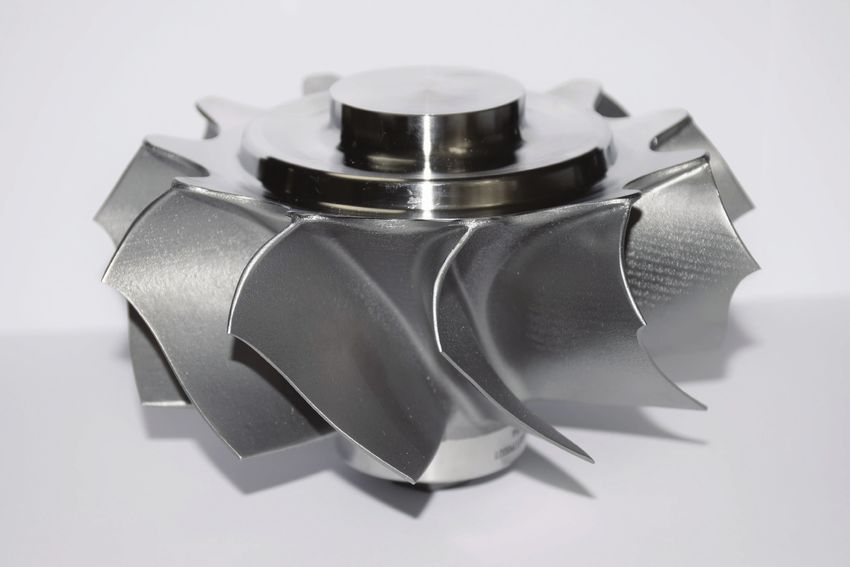
Table of
                                                    contents
Foreword                                    04

Bridging the Gap Between Design and         05   Optimize the Product Part, Not Just the   26
Additive Manufacturing Using Smart               Geometry- A Real World End2End
Generative Design                                Additive Manufacturing Solution
- Hendrik Schafstall and Raj Dua                 - Dr. Hendrik Schafstall

Fast and Accurate Additive                  09   Development of an Additive                31
Manufacturability Analysis                       Manufacturing Quality System for Gas
- Coriolis Composites                            Turbine Engine Part Production
                                                 - Samara University

Flexibility Through Additive                12
Manufacturing: How Simulation                    Robert Bosch India Use Simufact           36
Supports 3D Prototyping                          Additive to Digitally Lightweight a
- MBFZ Toolcraft                                 Fixture Tool and Save 70% in Mass
                                                 - Bosch India

Use of MaterialCenter for Metals Additive   14
Manufacturing Data Management                    Sinterline Prototyping by Solvay          39
- US Army                                        - Sylvain Mathieu & Dominique Giannotta

Use of Simulation in Additive               20   Simulating Effects of Warpage             41
Manufacturing Process Chain of                   - Bender Kutub & Olivier Lietaer
Thin-walled Automotive Parts
- Ampower
                                                 Author Profiles                           44
Simufact Additive: Collaborative            23
Simultaneous Engineering Tool for
Additive Manufacturing
- Safran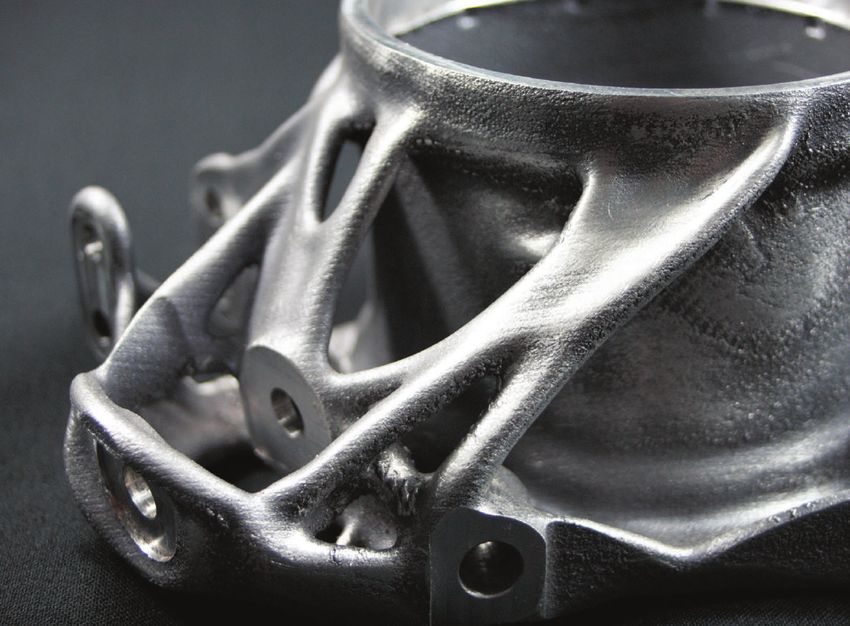
Foreword
                          For more than 30 years, dozens of Additive Manufacturing (AM) technologies have
                          been used to realize prototyping applications. AM is now becoming increasingly
                          widespread across industry sectors. We are starting to see additive manufacturing
                          being used in the serial production of high-tech parts, particularly in aeronautics,
                          space, and medical industries.

                          This e-book features some insightful commentary on the state of the additive
                          manufacturing industry and some of the dominant trends. In addition, it also
                          includes some compelling case studies that demonstrate the scope and range of
                          applications for simulation in additive manufacturing.

Today’s AM technology offers some major advantages, such as geometry design freedom that allows the
creation of optimized shapes according to the targeted function. Another key benefit of using 3D printing
technologies is the ability to reduce the weight, cost, and complexity of parts production without sacrificing
the reliability and durability of materials. AM affords the advantage of small production runs with less
material waste, significant energy cost savings, and the possibility to produce functional, high performance
parts that simply can’t be subtractively manufactured, cast or formed.

You can read about how engineers in Robert Bosch India are employing the Simufact Additive product from
MSC Software to model the additive manufacturing (AM) metal build process and subsequent
post-processing steps to help eliminate design errors before committing to AM. Similarly, there are use cases
from MBFZ Toolcraft, Ampower, Safran, Samara University, and Solvay, on various facets of additive
manufacturing. [each article can have separate three bullet points] on pages after foreword, or a short
summary which I have already included here].

The articles in this e-book also touch upon the concept of Generative Design that helps customers engineer
concepts unimaginable by the human mind and how this plays a role in enhancing the potential of additive
manufacturing.

As Additive Manufacturing becomes increasingly mainstream, this e-book intends to serve as a useful
compendium of useful insights on the role of simulation in additive manufacturing.

Dr. Hendrik Schafstall
Vice President, Virtual Manufacturing & Costing, MSC Software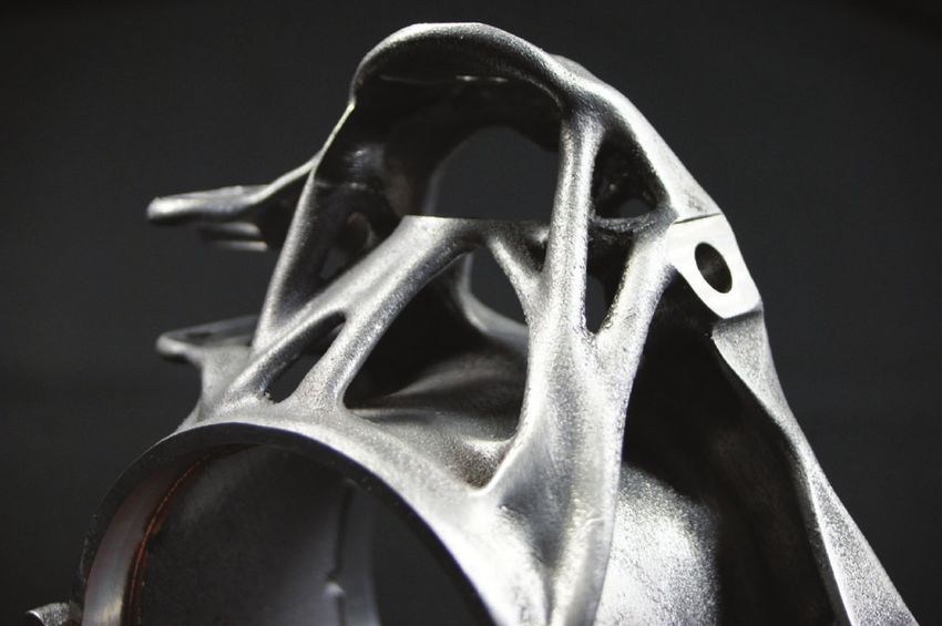
Bridging the Gap Between
Design and Additive Manufacturing
Using Smart Generative Design

By Hendrik Schafstall, CEO Simufact
Raj Dua, Product Manager,
MSC Apex Generative Design

                                      Additive Manufacturing | mscsoftware.com | 05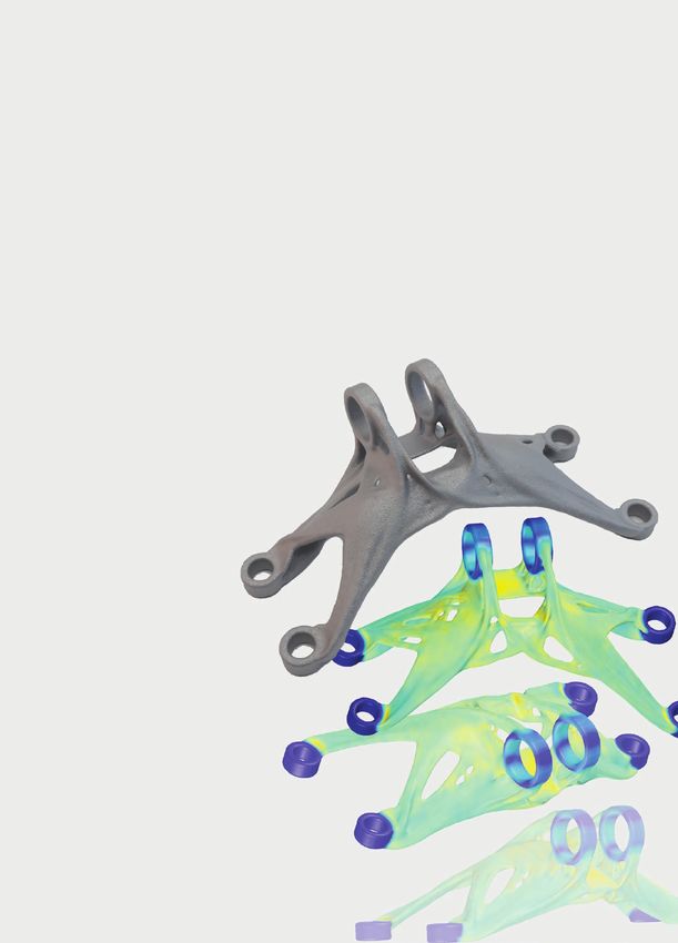
For MSC Software and Hexagon,
                                                            Generative Design is an initiative to
                                                         provide a tool that will help customers
                                                          design concepts unimaginable by the
                                                                                    human mind.

W
                       ith the release of MSC Apex Generative Design, MSC Software is
                       now offering an entire digital solution from the design to the final
                       validated part for all materials. Connecting design solutions like MSC
                       Apex Generative Design to virtual manufacturing simulation with            What is
                       Digimat AM or Simufact Additive, the design can account for the            Generative Design?
engineering and production phase challenges earlier in the product development phase.
As a digital twin, the virtual manufacturing simulation is used to identify the best printing     Simply stated, Generative Design is a
process and to optimize the orientation of the part and the build process. Furthermore,           process of automatically generating
the outcome of the additive manufacturing process chain can be used for the validation            several design concepts that satisfy
of the “real” geometry, while accounting for the residual stress distribution and the local       a set of user defined objectives,
deformation under real load conditions using MSC Software’s design validation solutions           criteria, and constraints. Generative
such as MSC Nastran or Marc. The end-to-end process enables engineers to make sure                Design can be accomplished in
their optimized designs are validated for manufacturability and performance.                      many ways depending on what
                                                                                                  criteria and constraints have been
                                                                                                  defined by the user. For example,
                                                                                                  if a user defines a set of structural
                                                                                                  loads and boundary conditions
                                                                                                  that a part must withstand as
                                                                                                  criteria, an upper stress limit as
                                                                                                  a constraint, and an objective of
                                      MSC Apex                                                    minimizing mass, a method known
                                  Generative Design                                               as Topology Optimization (which
                                                                                                  many of our MSC Nastran users
                                                                                                  are very familiar with) can be used
                                                                                                  to generate a number of design
                                                                                                  concepts that satisfy the given
                                                                                                  criteria and constraints. However,
                                                                                                  Generative Design is more than just
                                                                                                  Topology Optimization. For instance,
                                                                                                  a user may want to know what the
                                                                                                  best way is to package a number
                                                                                                  of electronic components in a given
                                                                                                  space in order to minimize the
                                                                                                  gap between all the components.
                                                                                                  Generative Design can help answer
                                                                                                  that question. For MSC Software
                                                                                                  and Hexagon, Generative Design
                                                                                                  is an initiative to provide a tool to
                                                                                                  our design customers that will truly
                                                                                                  act as a companion and help them
                                                                                                  think of design concepts that are
                                                                                                  unimaginable by human mind.

                                                                                                Additive Manufacturing | mscsoftware.com | 06
                                                                                                  Volume X - Winter 2019 | mscsoftware.com | 31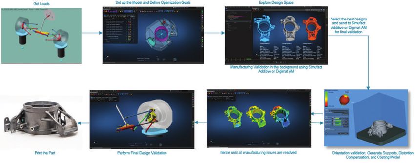
Why Do We Need                          are seen as two major constraints in wide        Each optimization always leads to a
Generative Design?                      adoption of AM for mass production.              geometrical and mechanical correct design
                                        Therefore, there is a need to account and        that can be used for manufacturing. In
                                        optimize for the total manufacturing costs       addition to the geometric side, the user
                                        and print time while designing parts for AM.     must also understand the cost and
                                        With MSC Apex Generative Design, we are          feasibility of using AM for this design
                                        focusing not only on optimizing the parts for    candidate. With MSC Apex Generative
                                        AM, but also optimizing the process for AM.      Design, our goal is to allow users to
                                        We believe that it is only after we bridge the   specify manufacturing related constraints.
                                        gap between design and manufacturing             For example, if the goal is to minimize
                                        that we can see AM become a sustainable          the cost of 3D printing, then MSC Apex
                                        manufacturing method.                            Generative Design will automatically check
                                                                                         each design candidate for: (a) amount of
                                                                                         material required for the part, (b) volume
                                        Bridging The Gap                                 of support structure required for support
                                                                                         and heat dissipation in the AM machine, (c)
                                        MSC Apex Generative Design is being              cost of removal of support structures and
                                        developed as a first-of-its-breed tool           machining for desired surface roughness,
The first release of MSC Apex           to bridge the gap between design and             (d) costs related to maximizing the number
Generative Design has been              manufacturing. Our goal is to automate           of parts printed at one time on a build plate,
released to assist design engineers     the process of Generative Design with            etc. These checks are performed in the
create organic topologies that can      user intervention only required for defining     background using MSC’s Simufact Additive
be manufactured using 3D printing,      the objective, criteria, and constraints         technology for metal parts and Digimat AM
i.e. Laser Powder Bed Additive          for design space exploration. MSC Apex           technology for polymers. At the end of the
Manufacturing. Technologies             Generative Design will then account              optimization routine, MSC Apex Generative
such as Topology Optimization           for how the part fits within the overall         Design selects the candidates that meet
are being reinvigorated thanks          assembly, how it redirects loads to other        the specified criteria and summarizes
to advancements in Additive             parts of the assembly as its stiffness           them. The design engineer can then export
Manufacturing. It is widely accepted    changes, and most importantly MSC                the selected design(s) in CAD format and
that Additive Manufacturing has         Apex Generative Design accounts for              perform further checks, for example, for
the ability to manufacture virtually    manufacturability – all automatically while      buckling, fatigue, and nonlinear for part
any topology. As a result, the          generating several design candidates that        performance or decide for one design
industry has seen a rise in the         all meet the user’s defined expectations.        based on additional reasons such as of
number of tools that allow creation     Many Generative Design tools in the              dirt problems or just aesthetic ones. The
of organic topologies via concepts      market today allow users to minimize             design engineer may also choose to send
such as Topology Optimization           the mass subject to a stress constraint.         the part to a manufacturing engineer to
and Generative Design. However,         The tool then solves a mathematical              perform further checks on manufacturability
if you have ever tried to 3D            optimization problem and produces one or         via Simufact Additive and/or Digimat AM.
print any “organic” topology            more design candidates. Although these           Users will be able to perform any geometry
that resulted from the Topology         candidates often are more ideas for a            modifications needed using the geometry
Optimization algorithm, you have        part and visualizations of how the forces        editing tools in MSC Apex. Eventually, MSC
probably realized that AM is not        flow through the design are. A proper            Apex Generative Design is able to perform
very forgiving, and an unrevised        Generative Design tool needs to produce          these checks during the optimization
Topology Optimization result often is   directly printable designs that can be used      process automatically as well.
far from feasible. Despite its unique   without any need for manual rework of
ability to manufacture virtually        geometry defects. This is what MSC Apex
any topology, AM still has many         Generative Design will deliver.                  Speed Is Crucial
limitations today. Issues such as
shrink lines, cracking, overheated                                                       In order to evaluate several design
zones, etc. have kept AM from                                                            candidates in a time effective manner,
replacing other manufacturing                                                            it is necessary to have a finite element
methods. These issues were not                                                           solver and an optimization engine
as pervasive when 3D printing was                                                        that can take advantage of the latest
only used for prototyping. However,                                                      computing technologies for extremely fast
they become prevalent when                                                               performance. With MSC Apex Generative
using AM for production parts,                                                           Design, we have done exactly that. We
especially primary or secondary                                                          have completely rewritten the FE solver
structural parts for Aerospace or                                                        and the optimization engine to scale on
Automotive industry. Today, cost of     Figure 2: Topology Optimization of a GE Engine   multiple GPUs and CPUs. The ability to
manufacturing and time of printing      Bracket using MSC Apex Generative Design         explore design space in a time efficient

                                                                                              Additive Manufacturing | mscsoftware.com | 07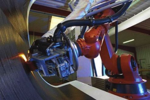
Figure 3: Design for Additive Manufacturing using MSC Apex Generative Design

manner ensures that the design process is          as possible while keeping into account           the full potential and benefits of AM, users
not a bottleneck and thus allows our users         the boundary conditions, constraints and         need to be able to produce designs that
to make decisions solely based on design           optimization goal. Thus, several design          are specifically validated for AM. With MSC
criteria. Only a complete examination of the       candidates are produced and directly             Apex Generative Design, we are developing
design space with a variety of results, and in     verified in the background using Simufact        technologies that validate manufacturability
a short time, leads to the best results.           Additive for metals or Digimat AM for            in the Generative Design process. As such,
                                                   plastic products. While selecting the right      the optimization engine only produces
                                                   candidate and iterating the manufacturing        geometry candidates that have been
Demonstrating The Potential                        simulation, the perfect design in terms          validated for AM.
                                                   of manufacturability, weight and costs is
To bring evidence on the potential of MSC          selected. As a last step in the virtual world,   Finally, after printing the part with your 3D
Apex Generative Design and to show                 this design finally gets a last validation       printer of choice, Hexagon metrology’s
its usability, a wheel carrier of a formula        with MSC Nastran for FE qualification            state-of-the-art scanners can verify the
student team is considered to demonstrate          and back again in Adams to ensure the            accuracy of the simulations and compare
a use case. Due to its very complex load           correct stiffness and behavior in the overall    the “as-built” part to the “as-designed”
cases and a high demand on lightweight             assembly. Thus, an optimal design was            part. This allows for genuine “First Time
design, it is the perfect fit for demonstration.   found that was printed and successfully          Right” 3D printing. Time and cost are two
Furthermore, there is a lot of experience          used in this year’s formula student season.      of the major constraints in wide adoption of
in optimizing this part, as this race series                                                        AM today. Typically, with MSC Software’s
officially is an engineering competition that                                                       Generative Design solution we find that we
requires to develop a new race car each            Summary and Conclusions                          can cut the time and cost of simulations
year. Other MSC tools such as Adams and                                                             by x10. Furthermore, most importantly,
MSC Nastran have been used for this part           MSC Software’s MSC Apex Generative               with our bridge to manufacturing, we find
in the past for optimization.                      Design is bridging the gap between design        that we can get closer to “First Time Right”
                                                   and additive manufacturing. Additive             3D printing. MSC Apex Generative Design
As shown in Figure 3, the development              Manufacturing has come a long way                technology is here to make the design and
process starts with retrieving the loads by        since its inception and is changing the          development for AM smarter and more
a multi body simulation based on Adams             manufacturing landscape. In order to realize     sustainable.
Car. Hereby, the overall suspension is
engineered, including all coordinates for
the connection points, as well as the acting                                                             Read an overview in our
forces. This information is used to set
up the optimization model and define its
goals. Therefore, a “design space” as big
                                                               Read an Overview in our Previous Issue for More
as possible is added (shown as translucent
                                                               Information on Hexagon and MSC’s End-to-End Solution:
material). In this case the overall inner space
                                                               www.mscsoftware.com/Engineering-Reality-Summer-2019
of the rim minus the installation space for
wishbones and braking system is selected.
Running the optimization, this material
in the design space is reduced as much

                                                                                                        Additive Manufacturing | mscsoftware.com | 08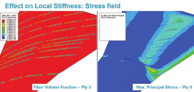
M AT ERIALS

          Fast and Accurate
              Additive Manufacturability Analysis

                                         By Yvan Blanchard, Coriolis Composites
                                        Anthony Cheruet, e-Xstream Engineering

                      T
                                   his article focuses on the design optimization of complex 3D composites
                                   structures made by additive manufacturing processes.

                                    There are commercial CAD-CAM software solutions for detailed offline
                                    path programming, but there is a growing need for innovative tools and
                                    methodologies for trade off studies very early in the design stage. A new
                      innovative solution has been developed on top of the CATFIBER© software, allowing both
                      designers and stress engineers to quickly analyze complex double-curved geometries. It
                      also includes a variable stiffness approach with tow-steering, and structural analysis of the
                      manufacturing defects using Digimat© software.

                      Design Analysis Framework Description

                      Today, more and more CFRP structures are manufactured by automated processes such
                      as fiber placement robotic systems (Figure 1).

                      The design trade-off analysis can be done on a simplified quasi-isotropic laminate (with full
                      plies), in order to just analyze the surface curvature impact, independently of plies shape.
                      But thickness effects, material excess, staggering rule, part productivity rate, could not be
                      correctly estimated.

                      The engineering and manufacturing requirements may quickly interfere, and a difficult
                      compromise between feasibility, strength and cost needs to be found, especially with
                      double-curved layup surfaces.

                                                                             Additive Manufacturing | mscsoftware.com | 09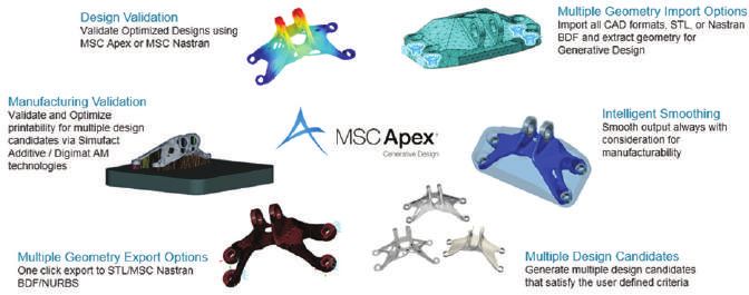
them test many combinations, such           Structural Strength Analysis
                                              as material width, maximum number
                                              of tows by course, and maximum              To verify the structural strength of the
                                              fiber deviation angle. The solution         optimized Layup design proposal, it
                                              should be able to analyze complex and       is important to have a quick and easy
                                              representative laminates such as large      transfer of all the as-manufactured
                                              aerospace panels with double curvature      composite properties onto a structural
                                              and hundreds of plies.                      mesh used for sizing purposes. This
                                                                                          mapping is done using the Digimat
                                              An automatic ply splicing algorithm,        Platform© and concerns the transfer of
                                              based on both engineering and
                                              manufacturing requirements, allows
                                              to quickly and easily generate a
                                              manufacturable design proposal. This
                                              algorithm also uses a patented rosette
                                              transfer feature, allowing steered-path
                                              propagation and then variable-stiffness
                                              modeling (Figure 2).

                                              Ply course centerlines and splice cuts
                                              are first computed, then the ply boundary
                                              is filled with (tow) strip surfaces. This
                                              allows us to capture all the process and
                                              material specificities, such as triangle
                                                                                          Figure 2: Steered-paths on wing skin surface.
                                              of gaps, tow overlaps, minimum course
                                              length (MCL), and minimum distance
                                              between tow cuts (Figure 3).

                                              The design analysis system is also
                                              able to compute and output several
Figure 1: Automated Fiber Placement robotic   manufacturing cost indicators, to help
system (Coriolis Composites)                  designers sort the manufactural design
                                              proposals (number of courses by
                                              sequence, number of tow cuts and drops,
                                              buy-to-fly ratio).
Moreover, such analysis systems are not
able to reach a good compromise between       The design analysis tools were
performances, level of details and results    implemented on top of Coriolis
accuracy. The expected computation            Composites CATFIBER© Offline
time is a few seconds to a few minutes so     Programming solution, through a
that several analysis runs can be done in     dedicated infrastructure made of scripts
parallel within a few hours only.             (Python or Visual Basic) and a Microsoft
                                              Excel© spreadsheet. This allows us to
                                                                                          Figure 3: Plies build-up with tape
Designers and stress engineers need           easily launch several background runs       courses covering.
robust tools and methodologies to help        from a very light user interface.

                                                                                              Additive Manufacturing | mscsoftware.com | 10
the as-manufactured fiber orientation, References
the exact location of the gap and
Wu KC. “Design and analysis of tow-steered
resin-rich area. Using Digimat, such
composite shells using fiber placement”.
information can be transferred In: Proceedings of the American Society for
automatically to the Finite Element Composites 23rd Technical Conference.
Model used for sizing activities by Memphis, TN, USA. 2008, doi: 10.4271/2012-
01-0082
Stress Engineers. In this case, Digimat
Fayazbakhsh, K., Arian Nik, M.,Pasini, D.,
can generate the composite layup Lessard, L., Defect layer method to capture
command cards with the local as- effect of gaps and overlaps in variable
manufactured fiber orientation for stiffness laminates made by Automated Fiber
Placement, doi: 10.4271/2012-01-0082
each ply. In addition, the effect of the
G. Gonzalez Lozano, A. Tiwari, C. Turner
gaps on the local stiffness can be A design algorithm to model fibre paths
handled in two ways, depending on the for manufacturing of structurally optimized
reconsolidation process. The first one composite laminates. In: Composite Structures
(2018), doi:10.1016/2018.07.088
considers that the gaps have an effect
on the local thickness while the second
one considers that the gaps are filled by
resin and affects the local fiber volume
fraction of the composite. Using a
micro-mechanical model of the material,
this local variation of the fiber content
Digimat can is computed at each Gauss point of the
generate the FE Model (Figures 4 & 5).
composite layup
command cards Figure 4: Thickness map analysis
(quasi-isotropic laminate) with tow gaps
with the local as- capture with Digimat© software.
manufactured
fiber orientation
for each ply.
Figure 5: Local stress field per ply and effect of gaps computed by Digimat©
For Details About CADFiber Standalone©, or CATFiber©
for CATIA Solutions: www.coriolis-composites.com
For Details About Digimat©:
www.mscsoftware.com/product/digimat
Additive Manufacturing | mscsoftware.com | 11AD D I TIV E MANUFA C TU R I N G
Flexibility
Through Additive Manufacturing:
How Simulation Supports
3D Prototyping
Simufact and its technology partner toolcraft shows
in a best practice case how additive manufacturing helps
to save time and money in the production of prototypes.
M
BFZ toolcraft GmbH require the component to have a long service process suitable for series production.
from Georgensgmünd life and high wear resistance so that it can However, before a new blade geometry
in Middle Franconia withstand mechanical and thermal loads. can be used with the required properties,
has optimized together many tests are required for which
with its software partner prototypes or small batches of blades are
Simufact Engineering from Hamburg the From Prototype to Series / required. In exceptional cases - depending
additive production of a turbine wheel Take a View On Manufacturing on the number of parts required - the
from ABB Turbo Systems AG. Typically, and Its Challenges in Serial turbine blades required for testing can
these components can be found in drive Manufacturing also be produced by casting in very small
units of heavy machines and vehicles, series. In general, these processes are
such as diesel locomotives, off-highway Filigree blade geometries are typically very time-consuming and cost-intensive
trucks or dump trucks. Depending on the produced by casting processes as and therefore not much more than two
application, manufacturers an economical and robust production prototypes are available to develop the
Additive Manufacturing | mscsoftware.com | 12CHALLENGE: Transfer prototyping SOLUTION: Generate variant diversity
into serial manufacturing. Using the with the help of additive manufacturing.
example of a filigree blade geometry we This technique helps you save time
consider the challenges of traditional and money. Reach the first-time-right
manufacturing. approach through simulation.
USED PRODUCTS: Simufact Additive USER: MBFZ toolcraft GmbH
final product for use in series turbines. Due to component geometry and thermal
At this point, additive manufacturing has stress, high stresses occur during the
become a key technology that saves time building process. This is due to the special
and money. Furthermore, the technology features of the geometry, which on the one
offers a maximum flexibility, one of the hand has a solid core with a lot of material
most important requirements in the field and volume, while on the other hand the
of prototyping. With the help of this blades are very filigree. As a result, there
innovative manufacturing process, a are large cross-sectional changes in the
variety of turbine blades can be produced component, which favour the residual
in a very short time, which ultimately stresses during the manufacturing
leads to a better product. This is where process. These in turn result in a high
MBFZ toolcraft‘s high manufacturing susceptibility to distortion.
competence throughout the entire value-
added chain in turbine blade production MBFZ toolcraft solves this problem with
proves its worth. Within the framework of a careful simulation-based as-is analysis
the cooperation between MBFZ toolcraft in which critical areas are identified. From
and ABB Turbo Systems AG, the products this, the necessary measures can then
can be designed and implemented as 3D be derived to counteract the distortion
printing right from the start. problem. This includes the development
of suitable support structures that
generally minimize distortion and thus
Simulation Provides Reliable ensure a safe construction process. But
Information on Distortion and the ideal alignment of the components
Stresses in the Component to be printed on the base plate can also
be very helpful in individual cases. The
For MBFZ toolcraft, the greatest challenge last step is an automated compensation
in manufacturing prototypes is maintaining of the remaining distortion based on a
the required tolerances and dimensional quantitative distortion analysis, with which
Image 1: Simulation helps to reduce component
accuracy. The decisive factor here is the the remaining distortion is determined. The distortion and thus to keep tight tolerances.
component distortion caused by the AM results obtained in this way can be used
process. In order to keep the distortions as to derive the print preparation. Thanks to
low as possible, MBFZ toolcraft relies on the simulation, MBFZ toolcraft achieves a
Simufact Additive. By using the user-friendly low-distortion component structure and
and process-oriented simulation solution, can thus remain to its “ first-time-right“
MBFZ toolcraft makes it possible to approach - to fulfil all requirements on
significantly minimize distortions by means the component with the first print. The
of suitable process parameters and to use of additive manufacturing enables
compensate where they cannot be avoided. MBFZ toolcraft to react flexibly and quickly
In this way, MBFZ toolcraft can meet all to customer requests, such as design
required tolerances, thus eliminating the changes, and thus to significantly reduce
need for time-consuming reworking. project lead times. The virtual engineering
offered by the powerful simulation solution
enables significantly tighter processes in
Problems and Challenges in the process development of 3D printing
the Building Process projects. This approach can be realized
through the reliable software Simufact
Image 2: From design to simulation to the
A closer look at the building process clearly Additive. finished component – less distortions thanks
reveals the challenges and problems. to Simufact Additive.
Additive Manufacturing | mscsoftware.com | 13M ATERIA LS
US Army Use of
MaterialCenter for
Metals Additive
Manufacturing Data
Management
Based on an Interview with the United States
Army Combat Capabilities Development
Command Armaments Center
T
he United States Army Combat Capabilities Development Command (CCDC)
Armaments Center is the US Army’s primary research and development arm
for armament and munitions systems. It is a leading defense facility for Additive
Manufacturing (AM) of Metals and is located in New Jersey. Armaments Center
has been investigating AM for a number of years now with programs aimed at
exploiting the novel capabilities of additive manufacturing. The facility has a number of AM
systems at their disposal including a laser powder bed fusion EOS M290 machine that prints
in Steel (4340/4140/17-4), Inconel, and Cobalt Chrome; and an E-Beam system, an ARCAM
A2X machine that prints in Titanium, Inconel, and Cobalt Chrome. In addition, there is access
to a wide range of support and testing equipment for powder synthesis (Plasma Reactors,
High Energy Mills), post processing (HIP, Heat Treatment, Surface Finishing), machining in
a full machine shop (EDM, CNC, etc.), testing (Tensile, Charpy Impact, Hardness), and part
characterization (Scanning Electron Microscopy, Particle Size Analysis, X-Ray Fluorescence &
Diffraction, Oxygen/Nitrogen Analysis).
Armaments Center is interested in using AM equipment to prototype, develop, and fabricate
metal parts via a layer by layer powder bed laser sintering process. AM has the potential to
provide a wide range of design flexibility over traditional manufacturing methods allowing for
rapid prototyping, part weight reduction, novel part design, reduced time to product, and
overall manufacturing flexibility. The benefits of AM include a reduced logistics footprint and
time-to-field for replacement parts, manufacturing options to reduce single point failures, and
creation of novel and improved part designs for reduced weight while meeting or exceeding
performance requirements. In turn AM results in a manufacturing process for providing parts
on rapid response, and on-demand basis.
Additive Manufacturing | mscsoftware.com | 14Armaments Center has identified six qualified for part acceptance for use
practical areas of interest for additive in armament systems meaning design
manufacturing technologies in the US and manufacturing process data
Army (see Figure 1): required to support repeatable additive
manufacturing production must be
1. Novel Materials: Novel powder defined. Several examples of additively
synthesis for Non-COTS materials, manufactured armaments produced are
2. Rapid Prototyping: Multiple build shown in Figure 2.
iterations on the same build plate for
design optimization. Small runs for
prototype testing,
3. Replacement Parts: Investigating
component replacements which
match properties but can be delivered
in an accelerated timeframe,
4. Novel Designs: Investigating novel
weapons systems components with
designs difficult or impossible with
traditional machining,
5. Rapid Fielding: Investigating Additive
Technologies to overcome the
challenges of bringing metals additive
to the field, and
6. Process Monitoring: Working to
develop custom In-Situ Monitoring
Hardware which can be retrofit on
existing equipment.
For AM benefits to be fully realized, Figure 1: Additive Manufacturing Areas of
processes must be developed and Interest to the US Army
Figure 2: Metals AM Build Examples for the US Army at CCDC Armaments Center
Additive Manufacturing | mscsoftware.com | 15What is the L-PBF and the constraints for AM. Today,
Quality Strategy? widespread adoption of the AM process
is limited due to a combination of these
CCDC Armaments Center at Picatinny, NJ, many challenges. Finally, with respect
have focused on additive manufacturing to utilization of Digital Product Data in
process development for AM materials and AM, a system for controlled electronic
parameters along with the development data management and sharing must be
of Quality Assurance provisions and implemented - software types used and
requirements to develop manufacturing digital file control must be set prior to
guidelines for robust and reliable new manufacturing initiation.
build L-PBF components. To do this, test
components for new build demonstration
and testing were selected. The team CCDC Armaments Center
wanted to establish a process for Additive Manufacturing
qualification and certification of AM Benchmark Demonstration
components, then transition the process
on to internal government facilities and the A CCDC Armaments Center goal is to
AM industry with a manufacturing guide. qualify powder bed fusion AM technologies
In addition, the US Army wanted to share as a viable alternative manufacturing
knowledge of the additive manufacturing process to fabricate armament systems
process and create a knowledge base of components. To do this, multiple areas
AM products aligning to their roadmap. in the total manufacturing process need
developmental efforts addressed to them to
be able to produce an accepted additively
What are the Challenges to the manufactured component. An additive
Figure 4: Selection of some of our 325 AM
Benchmark samples and parts Use of Additive Manufacturing manufacturing benchmark testing method
in the Military? was devised using 4340 Steel Powder
due to its chemistry, particle size, and flow
First and foremost, part acceptance for US characteristics. AM processing parameters
DoD (Department of Defense) applications were developed focusing on energy density
relies on a process for qualification and ranges, and a DoE (Design of Experiment)
certification. However, the relationship was established that looked at the following
between AM materials properties, parameters over 325 samples that were
processing parameters, and component fabricated (see Figure 4):
performance are extremely complex,
and complicated further by unique part 1. Laser Power
geometries. There is also an extremely large 2. Scan Speed
pool of materials and AM equipment to 3. Hatch Distance
choose from, raw materials must be readily 4. Energy Density Range
available and trusted to manufacturer or
internal specifications, processing condition The resultant AM parts were evaluated
windows must be defined to ensure part based on microstructure, density,
quality, In-Situ Monitoring technology must porosity, and hardness. Their mechanical
be utilized and improved upon, and a properties were compared to wrought
recognition that technology advancement steel after stress relief, quench and
might introduce previously unforeseen temper heat treatment.
manufacturing variables.
For each mechanical test specimen, four
It is fair to say that AM standards are still identical consecutive builds were printed
in development. There is a clear need to assess process reliability. The team
for continuing collaboration between focused on variations in location and
academia, industry, government agencies, orientation within and across builds, while
and others to push standards adoption. collecting tensile, hardness, density, and
Moreover, with respect to design for toughness data. The team normalized
Figure 5: Benchmark Steel 3d Printing Test AM there is a need to educate and samples with heat treatments per the
showing Locations of Parts of the Base Plate inform part designers of new principles AMS 2759 standard.
Additive Manufacturing | mscsoftware.com | 16Figure 6: Benchmark AM Printing Sample Mechanical Property Results for the different print Figure 7: Six AM Printer Machine results for the
locations in Figure 5 same set of parts being printed the same way
AM Benchmark Results and • Equipment chosen included an will occur. Complex data sets can be
Lessons Learned EOSM290, ProX320, SLM, and the generated from even a single build.
EOSM280 Hence, data storage solutions are needed
The tests indicated that parts printed • 4340 steel powder was procured from where process monitoring solutions
in the XY direction had 12% higher a single lot to minimize variance require large file storage spaces and
elongation values than parts built in the Z • A manufacturing guide was written bandwidth. In effect, AM processing
direction. Ultimate Tensile Strength (UTS), and disseminated to all participants pedigrees are required. There is a need
Density, and Hardness values matched outlining all major aspects of the for historical records of print builds to
wrought steel properties. The parts manufacturing process exist for data tracking and analysis to
printed at Location 2 (top left of Figure • The aim of this round robin test relate back to field performance without
5) had the lowest mechanical properties was to observe variance in material duplicating efforts, allowing teams to learn
(~9% less) of all builds. Build locations 2 properties as a function of orientation from mistakes or successes. To do all this
and 4 had Z oriented tensile data with the and plate location across equivalent raises big questions over IT infrastructure
lowest values (see table in Figure 6). This and different equipment types, with issues. If there is no uniform software and
was because gas flow worsened when the same or equivalent process network system across different branches
the machine’s filters were nearly full. In parameters. and centers, then it will be difficult for
addition, many AM process conditions approvals and data sharing to happen
needed to be taken into account such as with additively manufactured parts.
powder coverage, build plate material/ AM Engineering Simulation
condition, recirculating gas filtration, Digital Data Storage Challenges
gas flow rates, part orientation, and part MSC’s MaterialCenter as the
location on the underlying build plate and In particular, given the sensitive nature of AM Data Management Solution
these parameters must be controlled military parts, data security is critical in AM at CCDC Armaments Center
for consistent AM part mechanical – how is digital data adequately protected
properties. Hence, a manufacturing in additive manufacturing? How is data To overcome digital data challenges of
plan with defined operating windows is sharing implemented especially if different additive manufacturing, a software solution
needed to ensure parts are consistently network security protocols exist, where is necessary for traceability, storage,
made to specification. cloud-based solutions are not widely and analysis of simulation material data.
adopted? Moreover, in terms of data Armaments Center used MSC Software’s
classification where data aggregation could MaterialCenter (Figure 8) and developed
The Effect on the AM raise the classification, there is a need for an additive manufacturing schema to
Benchmark Tests on Using a controlled system. Invariably, different enable the storage of all printer machine
Different Machine Types formats occur across a wide variety of parameters along with corresponding
OEM machines for metals AM with no material properties. It utilizes M/S Excel
To check for the effect of different additive standardized software or file format. integration in order to map and import
machines, six AM commercial machines custom templates. The data collected is:
were chosen to print the same parts in a In terms of data organization, a unified file
“round robin” demonstration of variability structure does not in general exist. With • Machine Information
(see Figure 7): AM, large amounts of data generation • Part Data (CAD/STL/MAGICS Files)
Additive Manufacturing | mscsoftware.com | 17• Starting powder properties
• Machine Build Parameters
• Build Layout and Orientation
• Laser Parameters
• Post Processing
• Metallographic Analysis
• Mechanical Testing Data
The data stored using MSC Software’s
MaterialCenter involves a flexible schema
for different applications, an automated
method for input of material process
information, data analysis to compare
and contrast properties and understand
how to optimize them, and finally allowing
traceability of test data. Figure 8: MSC MaterialCenter in the center of the entire AM Material Lifecycle workflow
Capturing the Entire AM at CCDC Armaments Center - this is
Material Lifecycle shown schematically in Figure 11 where
the integration between Windchill and
Figure 8 shows the data tracking process MaterialCenter for additive manufacturing
for additive manufacturing and Figure 9 is shown pictorially. The benefits of
depicts the two parts of the AM process: this system are that it is always up-
to-date for version control tracking; it
1. “Left of Test” where manufacturing leads to less duplication of efforts and
inputs that are used to create a part therefore reduced costs; it is a common
or specimen are captured. This side file system for traceability, file security, This additive manufacturing ePDM
of the test leverages MaterialCenter’s historical storage, etc; it provides for workflow helps to deal with the
Work Request, Pedigree and a better collaborative environment in management of data issue and can
Process features. MSC Software’s order to coordinate efforts; it allows for become a US Army Standardized
MaterialCenter tracks the test quicker fabrication of hard to replace Tool for Lifecycle support when
specimen from raw material through parts with standardized file systems printing a component. It provides
the complete specimen build process and organization; it yields common data confidence through validation to
(Figure 10). The team tracked the models for standardization and validation; the end user of part performance.
materials & the environment, Batch/ it is a single source of data for linkage Everything is in the chain from raw
Specimen numbers and the Part between systems; and it provides true material, files, machines, and post
Inspection. lifecycle configuration management for treatment and it is validated to
2. “Right of Test” where Material products additive manufacturing. In short, for perform as designed. In terms of
are tracked from test to export. us to make Additive Manufacturing as Data Capture, automated processes
“available” as traditional manufacturing to feed into the data management
Finally, PTC Windchill was chosen as the techniques, materials and process data, system were enabled. In terms of
ePDM system for this application and it must be linked to part data using this On-Demand Manufacturing, the
the overall central data system for AM enterprise ePDM approach. team has qualified and authorized
personnel with access to the data.
In terms of Predictive Modeling,
knowing how a part will perform
before printing is invaluable. In terms
of Cooperation & Data Sharing, it
will lead to the saving of money and
time by building on the most up-
to-date work. And, lastly, in terms
of Data Analysis, the team can
optimize process parameters via
statistical modeling and understand
the relationship between key AM
process parameters.
Figure 9: Data management applied to additive manufacturing process
Additive Manufacturing | mscsoftware.com | 18Future Focus of Additive
Manufacturing in the US Army
The US Army CCDC Armaments Center
is aiming at integrating material data
management with other enterprise
software, eg. PLM, and collaboration with
other services such as the US Air Force,
US Navy, etc. Ultimately, this approach
can be expanded to other manufacturing
processes and the capture of legacy
manufacturing data with the creation
and storage of new data libraries. It is
also looking at new materials systems
(functionally graded materials, novel
alloys, hybrid materials), the fielding of AM Figure 10: Overall Flowchart of Additive Manufacturing Data
parts and AM systems for on-demand
Battlefield manufacturing, a wide range
of qualification & certification of materials,
processes and parts via additive Reference
manufacturing, and advanced fabrication
“Army Efforts in Metals Additive Manufacturing & Data Management”, R. Carpenter, SME Smart
integration with sensors and electronics.
Manufacturing Series – Additive Manufacturing, 07 June 2018
Figure 11: PTC Windchill and MSC MaterialCenter integration ePDM system for Additive Manufacturing Data
Additive Manufacturing | mscsoftware.com | 19
VUse of Simulation in
Additive Manufacturing
Process Chain of Thin-walled
Automotive Parts
By Dr. Maximilian Munsch,
Ampower GmbH & Co KG
For more than 30 years, dozens of Additive Identifying automotive PBF-L applications becomes
Manufacturing (AM) technologies have been used for challenging when taking the industry’s high demands
realizing prototyping applications. Over the past few regarding cost, quality and time into account.
years, AM was increasingly adopted for serial Because of the cost per volume of AM parts,
applications throughout industry, such as medical or currently only high priced, low volume vehicles or
aviation. The process of powder bed fusion with racing sports cars are targeted for application
laser beam (PBF-L) of metals has the largest impact. screening. In automotive production for mass
It offers the highest degree of freedom of design and markets, cost per part dominates the final decision
flexibility as well as excellent material properties. on whether they will be manufactured additively or
Additive Manufacturing | mscsoftware.com | 20Figure 1 Additive Manufacturing process chain
conventionally such as forging or casting. the engine’s performance to the customer’s eye.
Manufacturers of high performance sports cars with Conventionally, those blends are manufactured from
limited quantitities up to approximately 5,000 units stainless steel or titanium alloys. Two metal sheets
per year will be early adopters of AM. Ampower formed by deep drawing are joined by a welding
expects the largest potential in automotive seam. Requirements for the mechanical properties
applications to be in the power and drive train as well are driven by vibration and corrosion which put high
as the suspension system. stress on the welding seam. Additionally, tail pipes
are subject to major design iterations. This leads to
To analyze the status quo, Ampower conducted a remanufacturing of deep drawing tools at extremely
study on Additive Manufacturing of a high-end high cost and typical lead times of over 12 months.
automotive application - a tail pipe blend from a
Porsche GT2 RS sports car and analyzed the AM rarely make sense without exploiting the
complete AM process chain. Tail pipe blends are the potential of redesign. A redesign has to consider
visible part of the engine exhaustsystem. Optical not only specific parts but also all surrounding
requirements are high since the component reflects components, functions and assembly steps. For the
present application, realized redesign advantages
are short time to market due to tool-free
manufacturing, increase of quality due to
homogenous material properties, reduction of
number of parts – and thus less assembly steps
– and potential for customized design.
Figure 2 Re-designed, printed and post-processed tail pipe Figure 3 Results of simulation with Simufact Additive and
blend of sports car Porsche GT2 RS computer tomography measurement of printed part
Additive Manufacturing | mscsoftware.com | 21The AM process chain used for production of the tail
pipe blend is displayed in Figure 1. The final part
manufactured with PBF-L using titanium alloy
Ti-Al6-4V is shown in Figure 2 .
For complex free-form surfaces, optical 3D scanning,
e. g. with Hexagon metrology devices, and computer
tomography (CT) imaging are well suited methods to
accurately measure the resulting geometry. In this
study, the results of CT imaging were used to assess
Figure 4 Detection of shrink lines with the new function the feasibility of simulation tools that allow prediction
inside Simufact Additive
and compensation of stress-induced deformations.
The overall accuracy is mostly affected by distortion
and part shrinkage from residual stress formed
during the PBF-L process, where material cools at
rates of several thousand Kelvin per second.
The simulation of the PBF-L process was
conducted with Simufact Additive using the inherent
strain model. The voxel size for discretizing the CAD
data was set to 2 mm – the range of the wall
thickness of the part. The simulation yielded a
stress distribution and a prediction of the shape
About Ampower: deformation. The comparison of the results of the
simulation and the CT measurement are displayed
Ampower is the leading consultancy in in Figure 3. The conducted simulation shows a
the field of industrial Additive good match of absolute range of distortion, and the
Manufacturing. Ampower advises their deviation is represented quite well.
clients on strategic decisions by
developing and analyzing market Further analysis was done in collaboration with
scenarios as well as compiling technology Simufact headquarters in Hamburg employing a
studies. On operational level, Ampower brandnew function to detect specific part defects -
supports the introduction of Additive so-called ‘shrink lines’. Such shrink lines are formed
Manufacturing through targeted training in layers where manufactured areas grow together,
program as well as identification and shrink during solidification and leave visible marks on
development of components suitable for the surface. These defects were visible at the upper
production. Further services include the region on the tail pipe blend after production as
setup of quality management and support displayed in Figure 4. The part defects were correctly
in qualification of internal and external predicted by the simulation software and will allow
machine capacity. The company is based for future compensation.
in Hamburg, Germany. More about
Ampower at am-power.de. In conclusion, the study revelaed the feasibility for
use of PBF-L process of thin-walled automotive
Contact: parts. However, the relative high cost of the
process will limit the use to high end applications
Ampower GmbH & Co. KG with low volume. Simufact Additive predicted the
ZAL TechCenter deformation and shrinkage correctly and will allow
Hein-Saß-Weg 22 improved process chains by enabling first time
21129 Hamburg, Germany
right production.
Dr. Maximilian Munsch
munsch@am-power.de
+49 175 8787870
Additive Manufacturing | mscsoftware.com | 22Simufact Additive: Collaborative
Simultaneous Engineering Tool
for Additive Manufacturing
By Clara Moriconi, Head of Safran Additive Manufacturing’s Methods,
Tools and Application Team, France
A
dditive manufacturing is a process that has been used Additive manufacturing of metal components is becoming
for some years in Safran’s production centers. Safran more and more widespread in all sectors of industry. A major
Additive Manufacturing - a technology platform advantage of this technology is the geometry design freedom
attached to Safran Tech, Safran’s dedicated research center - that allows the creation of optimized shapes according to the
is aiming to support the widespread use of the additive targeted function. It now starts to be used for the serial
manufacturing technology within the Group: first by production of high-tech parts, particularly in the aeronautics
recommending tools and standards while evaluating and and space industry. Another key benefit of using 3D printing
validating the solutions through use cases, then by technologies is the ability to reduce the weight, cost and
accompanying the companies of the Group in the deployment complexity of parts production without sacrificing the reliability
and use of these tools. and durability of materials.
Additive Manufacturing | mscsoftware.com | 23The Additive Manufacturing Challenge
Although some applications are already in production, many
are still at the proof-of-concept stage. Thus, in order to expand
the use of additive manufacturing and make the most of this
technology, it is essential to accelerate the capability to model
additive manufacturing processes in detail - and more broadly,
to improve the understanding of the technology by the relevant
employees within our Group.
The Methods, Tools and Application team of Safran Additive
Manufacturing is operating in this context. The objective of the
team is to evaluate and qualify additive manufacturing process
simulation solutions, and then facilitate their deployment within
the various Safran operating units.
Figure 1: Example of the effect of a 3D printer scraper / workpiece
collision on the powder bed
Figure 2: Example of macro-cracks on LBM parts that appeared during the manufacturing process due to part distortion and Simufact Additive stress
predictions of the parts (Red is high, blue is low)
Additive Manufacturing | mscsoftware.com | 24Simulation of the Additive and post-treatment operations, risk of collision with the
Manufacturing Process recoater, as well as the possible risks of failure of the part itself
or the supporting structure attached to the part. Figures 1 and
One of the manufacturing processes in which Safran Additive 2 illustrate two types of failures that can happen in additive
Manufacturing is more specifically interested in, is the Laser manufacturing: 3d printer scraper / workpiece collision in the
Beam Melting (LBM) process. The simulation of this process powder bed during the manufacturing process, and large scale
aims at identifying issues associated with part distortion during crack formation during the 3d printing process due to inherent
the manufacturing process, as well as the potential risks of stresses in the part during the manufacturing process
failure of the part and its supporting structure.
The Benefits of Simufact Additive to Safran
Safran called on MSC Software, which offers a solution that
uniquely covers the entire manufacturing process, from the The use of Simufact Additive has enabled us to save
initial melting step of the part to the completion of a final HIP considerable time in production preparation thanks to the
treatment (Hot Isostatic Pressing), including all post-processing predictive nature of the software, which limits development by
operations such as a stress-relaxation heat treatment, manufacturing iterations by using virtual development
baseplate cutting and supports removal. This solution is upstream, but also during the part design phase, by enabling
Simufact Additive. us to anticipate the effects and limitations of the process at the
product design level.
Safran Additive Manufacturing uses the software iteratively as
part of our feasibility studies for the following two applications: One of the added values of the Simufact Additive solution is
that it allows us to bring together two activities: engineering
• For production support: to virtually develop and validate and production. On the one hand, people from engineering
the process, in order to reduce physical iterations on who design parts with a strong focus on part performance in
the machine; service, and, on the other hand, the methods office who
• Further upstream, in the product design phase: to check master the industrial processes and their associated
the manufacturability of parts and to take into account the constraints. Simufact Additive is a solution well adapted to
specific constraints linked to the process during the simultaneous engineering that facilitates dialogue between
product design phase. the different business activities involved in the same project.
In addition, the software is easy to use, with an intuitive,
Simufact Additive allows for the identification of potential issues business-oriented interface that allows for quick and easy
due to deformation of parts during the manufacturing phase appropriation/ownership.
Conclusions
Safran Additive Manufacturing has taken full advantage of the added value of the Simufact Additive solution in order to secure the
integration of the additive manufacturing processes into its “product-process” development processes, both upstream during product
design and downstream for the production launch.
Safran Additive Manufacturing is now focusing on extending the use of the Simufact Additive solution to different types of parts and
different grades of material, in order to improve the design process for additive manufacturing as a whole. MSC Software supports Safran
Additive Manufacturing and the Group in achieving this objective through this solution that integrates into the global additive manufacturing
value chain, ensuring a quality and open digital continuity.
Try Simufact free for 30 days! Learn how: www.mscsoftware.com/simufact
Additive Manufacturing | mscsoftware.com | 25Optimize the Product Part,
Not Just the Geometry
- A Real World End2End
Additive Manufacturing
Solution
By Dr. Hendrik Schafstall, Vice President,
Virtual Manufacturing & Costing, MSC Software
W
ith the continuing rapid adoption and development
of additive manufacturing techniques and
technologies in multiple industries led by
can be obtained in companies. This includes the huge potential
for lightweighting, small production runs with less material
produce functional, high performance parts that simply can’t
be subtractively manufactured, cast or formed. One of the
challenges is a full automation and to minimize the physical
try-outs. This can only be achieved with a full digital
With the acquisition of MSC Software in 2017, and its
manufacturing oriented and material focused business units of
Simufact and e-Xstream in particular; Hexagon’s Manufacturing
Intelligence Division now has in its portfolio a unique
combination of tools including cutting edge CAD/CAM
production software plus existing market leading metrology
solutions. The smart factory solution Xalt from Hexagon is
offering the needed framework for the connecting of all data
(from real and virtual sources) to enable a fully connected Figure 1: End2End Workflow for Virtual Simulation, Printing and
Scanning in Additive Manufacturing
Additive Manufacturing | mscsoftware.com | 26You can also read