Agua Prieta Building Plans - How to build a quality ladrillo shelter - Steve Wilson John Benson
←
→
Page content transcription
If your browser does not render page correctly, please read the page content below
Agua Prieta Family Shelters, Inc.

Agua Prieta Building Plans

How to build a quality ladrillo shelter

Steve Wilson              Roger Schneider

John Benson               Donna Lewandowski

2nd Edition April, 2002

Agua Prieta Building Plans

           Second Edition

                   By
          Roger Schneider
           Steve Wilson

           Editing and Layout
        Donna Lewandowski

               Illustrations
             John Benson

                 Printing
             Jeff Lyster
          Copy Cat Copies
            Phoenix, AZ

     Agua Prieta Family Shelters, Inc
                  2002
Agua Prieta Family Shelters, Inc.
Roger Schneider, President
Kip Thompson, Vice President
Steve Wilson, Secretary
Frank Fountain, Treasurer
Steve Washburn, Board Member
A Non-Profit Corporation
4431 N. Wolford Rd.
Tucson, AZ 85749
APShelters@aol.com
Copyright © 2002 Agua Prieta Family Shelters, Inc.
Volunteers Building Shelters for Poor Families in Agua Prieta, Sonora, Mexico
First Printing
Printed in the United States of America1 Table of Contents 1 TABLE OF CONTENTS I 2 TABLE OF FIGURES III 3 INTRODUCTION 1 3.1 Mission 1 3.2 Acknowledgements 2 4 GENERAL BUILDING NOTES 3 4.1 Building Summary 3 4.1.1 The Foundation 3 4.1.2 Walls 4 4.1.3 Windows 6 4.1.4 The Dala (Bond Beam) 7 4.1.5 Roof 7 4.1.6 Doors 9 4.2 The Agua Prieta Environment 9 4.2.1 How to mix mortar and concrete 9 4.2.2 Availability of Water and Power 10 4.2.3 Food, Water and Sanitation 10 4.2.4 How They Make the Ladrillos 11 4.2.5 What to Bring with You 11 5 CONSTRUCTION DETAILS 13 5.1 Building the Foundation 13 5.1.1 Site layout 13 5.1.2 Determining the footing elevation and marking for excavation 15 5.1.3 Continuous Footing 17 5.1.4 Stepped Footing 18 5.1.5 Setting stakes for the footing height 19 5.1.6 Installing rebar in the trench 20 5.1.7 Pouring the concrete 21 5.1.8 Setting the corner blocks 21 5.1.9 Setting the remaining cinder blocks 22 5.1.10 Filling the cinder blocks with concrete 23 5.2 Building the Ladrillo Walls 24 5.2.1 Setting the speed-leads 24 5.2.2 Laying Out the 1st course of ladrillo 25 5.2.3 Setting the block line 26 5.2.4 Setting the ladrillo in mortar 26 5.2.5 Raising the line 27 April, 2002 Second Edition i
5.2.6    Setting subsequent courses                                28
     5.2.7    Cutting ladrillo to fit                                   28
     5.2.8    Putting Dur-o-Wal in the wall                             28
     5.2.9    Placing the J-bolts for the door frame                    29
     5.2.10   Keeping the door opening plumb                            30
     5.2.11   Making the window openings                                31
     5.2.12   Slotting the final window opening                         32
     5.2.13   Striking the joints                                       32
     5.2.14   Using the scaffolding                                     33
     5.2.15   General cleanup                                           33

5.3    Installing the Windows                                           34
  5.3.1     Trimming the top flange                                     34
  5.3.2     Putting the window in the slot                              34
  5.3.3     Cleanup after the Dala is built                             34

5.4    Building the Dala (Bond Beam)                                    35
  5.4.1    Installing the Windows                                       35
  5.4.2    Preparing the reinforcing steel                              35
  5.4.3    Installing the Dala Forms                                    36
  5.4.4    Adding lintels for the doors and windows                     39
  5.4.5    Filling the form with concrete (pouring the Dala)            39
  5.4.6    Setting Anchor Bolts                                         40
  5.4.7    Low Roof Wall Dala J-Bolts                                   41
  5.4.8    The High Roof Wall Dala L-Bolts                              42
  5.4.9    Building the Pony Wall                                       44

5.5    Installing the Roof                                              46
  5.5.1     Removing the Dala Forms                                     46
  5.5.2     Installing the Plate Material                               46
  5.5.3     Rafter and Frieze Board Installation                        48
  5.5.4     Fascia Board                                                50
  5.5.5     Stringer Cutting and Installing                             52
  5.5.6     Caulking the frieze boards                                  53
  5.5.7     Installing the foam and roofing metal                       53
  5.5.8     Installing insulation against the frieze boards             59

5.6    Finishing the Window Installation                                60
  5.6.1     Building the windowsills                                    60
  5.6.2     Caulking                                                    61
  5.6.3     Cleaning and screen installation                            61

5.7    Installing the Doors                                             62
  5.7.1     Hanging the Doors                                           63
  5.7.2     Installing the Buckboards and Header                        63
  5.7.3     Installing the Metal Frame                                  64
  5.7.4     Finishing Up                                                65
  5.7.5     J-Bolt Problems                                             66
  5.7.6     Caulking Around the Door Frames                             67

6      GLOSSARY                                                         70

ii                                              Second Edition   April, 2002
2 Table of Figures
• Figure 1 - Outside Squaring Technique...............................15
• Figure 2 - Site Layout............................................................16
• Figure 3 - Footing Detail........................................................17
• Figure 4 - 4" Step Diagram ...................................................18
• Figure 5 - 8" Step Diagram ...................................................19
• Figure 6 - Footing Stakes in Trench.....................................20
• Figure 7 - Rebar Layout ........................................................21
• Figure 8 - Setting Corner Blocks ..........................................22
• Figure 9 - Speed-lead Setup.................................................25
• Figure 10 - Ladrillo Mortar.....................................................27
• Figure 11 - Dur-o-Wal Installation.........................................29
• Figure 12 - Door Frame J-Bolt Installation ...........................30
• Figure 13 - Window Frame Slot............................................32
• Figure 14 - Dala Clip Installation...........................................37
• Figure 15 - Dala Form Inside................................................38
• Figure 16 - Dala Form Outside.............................................39
• Figure 17 - J-Bolt Installation ................................................42
• Figure 18 - L-Bolt Installation ................................................43
• Figure 19 - Pony Wall Speed-leads .....................................45
• Figure 20 - Plate Installation .................................................47
• Figure 21 - Rafter Layout ......................................................49
• Figure 22 - Fascia and Stringer Layout................................51
• Figure 23 - Fascia and Metal Edging ...................................52
• Figure 24 - Styrofoam Placement.........................................55
• Figure 25 - Metal Over Styrofoam ........................................56
• Figure 26 - Roofing Material Overlap ...................................57
• Figure 27 - Windowsill Form.................................................61
• Figure 28 - Buckboard Installation........................................64
• Figure 29 - Door Frame Installation......................................65
• Figure 30 - J-Bolt Fix-up........................................................67
April, 2002 Second Edition iiiNOTES iv Second Edition April, 2002
3     Introduction

 3.1      Mission

              Building a shelter for those less fortunate in Agua Prieta can be a very special experience.
              It can be very gratifying to be able to positively impact the lives of so many by volunteering
              a relatively small amount of your time and effort.

              The building process in Agua Prieta can be very challenging. For those skilled in the art of
              homebuilding, the quality and availability of materials can be very frustrating. For those
              without experience, the process can be very confusing and difficult.

              When you hear someone talking about building in Agua Prieta, you will often hear the
              word shelter used instead of house. We have found in describing our work to others the
              use of the word house is misleading. With the use of the word house, the assumption is
              we are building something similar to the work done by the group Habitat for Humanity.

              The shelter consists of 4 adobe walls, 3 to 4 windows, 2 doors, and a roof. The floor is
              dirt, and there is no plumbing or electricity. The walls are not insulated. The home for a
              family of 4 to 10 people is 400 square feet in size. The shelters are constructed for
              approximately $6 per square foot, less than 1/10 the cost of construction in the United
              States.

              There is no doubt what we build is a rudimentary shelter by our standards. There is also
              no doubt what we leave behind is a home for a family.

              Because of what we are accustomed to in our everyday lives, the shelters resulting from
              your efforts will not be something you would necessarily want to live in. Despite this fact,
              in every instance the new shelter will be a significant upgrade in living conditions for the
              new occupants. While the shelter will be substandard by our standards, there are still
              several things to keep in mind to build the best possible shelter with the materials and
              labor available. Our goal is to build every shelter as well as possible.

              We want to build and complete as many shelters in the shortest time possible. Our goal is
              to help as many families as we possibly can. We usually try to finish up as many partially
              built shelters as we can in the fall and build a complete shelter from start to finish in the
              spring. Many mistakes and things to avoid are listed in this document. We have either
              made or have seen every mistake we will refer to and we have experienced first hand the
              consequences of each of these mistakes. With this in mind, many tricks and techniques
              are included in this booklet to enable shelter building to go quickly and produce a high
              quality ladrillo shelter.

              If you follow the guidelines in this document you should be able to build a better shelter in
              less time, which should make your Agua Prieta experience more enjoyable. If you come
              across additional tips and techniques, please let us know and we’ll add them to this
              document for others to use. Send updates and new info to wilsons@us.ibm.com.

              Our goal with this document is to share the knowledge and experience we have gained
              with a few years of shelter building in Agua Prieta to hopefully enable you to have an
              enjoyable and satisfying experience.

April, 2002                                     Second Edition                                                1
3.2 Acknowledgements
This ministry and outreach would not be possible without the help of several very
dedicated individuals. The Emmanuel Lutheran Church in Douglas serves as a wonderful
base camp and host to numerous groups from all over the United States.
Dorothy Millett is a wonderful hostess who has provided countless breakfasts, dinners,
and food supplies to an endless stream of builders. She manages to make everyone feel
at home.
Pastor John and Nina Lundering help keep the program running and fill in with a helping
hand when needed.
Robert Spearman is a Douglas resident who accompanies us to Agua Prieta every time
we go. Robert is our translator and general helper. He has made countless runs to local
merchants for every supply imaginable. He’s been a big help.
A special thanks goes to Kip Thompson, Frank Fountain, Tony and Pat Everett, Steve
Wilson, Jr., Jim and Sandie Jacobson, and Bill Borland for their continuing dedication and
hard work. Additional thanks go to the myriad of people who also performed exceptionally
in the building process, too numerous to mention here.
Finally, the man who makes it all happen is Dan Schoenfelder. There are not enough
pages in this booklet to adequately describe all of the things Dan does. To us he’s just
Dan “The Man”. To the families in Agua Prieta, he is likely “An Angel”.
2 Second Edition April, 20024 General Building Notes
There are several stages to building a ladrillo shelter in Agua Prieta. In this section you
are given an overview of these stages. Subsequent sections will add much more detail
about each stage. Building a complete shelter will take four to ten days depending on the
number and skill of the workers, the availability and quality of materials and weather
conditions.
There are several processes that can be overlapped or done in parallel and several which
cannot. We will try to highlight which can and cannot and any critical sequences that must
be followed. Depending on how many days you are able to work and how many times
you can return, you may or may not be able to experience every stage of construction.
Being from Tucson, we have had the luxury of being able to build a number of shelters
from start to finish, which has given us a unique perspective of how things fit together and
which parameters can be critical.
We’ve had the opportunity to complete a number of shelters started by other mission
groups. When we say avoiding certain mistakes will save hours of time later, it is from
personal experience. What we have seen from others and done ourselves covers about
every mistake we will refer to in the detailed instructions.
Some minor errors can be nothing more than an annoyance, others can cause several
hours of delay or cause the waste of significant amounts of material. Given the
construction time in Agua Prieta is so precious we would like to help you avoid both.
Every step and process in this document has a purpose. We will try to explain each as
much as possible. Taking short cuts or leaving steps out could cause more work for you
or others, or result in a shelter not as structurally sound or as aesthetically pleasing as it
could be.
4.1 Building Summary
What follows is a summary of the six major elements of building a shelter. With good
planning and a little luck, you can expect to accomplish the entire task in six working days.
4.1.1 The Foundation
The foundation, as its name implies, provides the structural base for the entire shelter. It
consists of a steel reinforced concrete footing and a cinder block stem wall, which rises
above the surrounding grade. The ladrillo used for the shelters (fired mud blocks), are
only a weather-resistant building material, therefore they must not be set below grade level
or in any placement where they can become wet for a prolonged period of time. They are
extremely porous, and prolonged exposure to moisture will result in quick deterioration
and structural failure of the ladrillo bricks.
The footing should not be above grade level more than an inch or two at any point
because it is not formed. The goal is to provide a footing allowing the cinder block stem
wall to extend at least 2 to 3 inches above the grade level. Because of this and the
requirement to keep the ladrillo above grade level, you will have about 8 inches of grade
April, 2002 Second Edition 3change you can tolerate from the lowest point of the shelter to the highest point before a
step in the footing must be used.
It’s nice to avoid having to build a step in the footing because the step requires more work
and skill to set up and pour, and it will require more time and materials to lay additional
block in the stem wall to bring it up to a uniform level. However, if the grade delta across
the length of the shelter is over 8”, a step usually cannot be avoided. Laying one course of
cement block is challenging enough because of their nonstandard shape and irregular
dimensions. Laying more than one course is not something to look forward to.
It is important to properly prepare the rebar used in the footing. The rebar is critical to
providing strength to the footing. Without it, or if it is improperly installed, the foundation
may move or settle over time resulting in cracks in the walls. Details on how to properly
prepare and install the rebar will be provided under the construction details section.
The height of the footing is critical. If it is slightly low it generally is not a problem and is
dealt with by using a little extra mortar when laying the cinder block stem wall. Too high a
footing is a more significant problem. If the error in height is more than the nominal mortar
joint for the cinder block, you will not be able to maintain a consistent elevation of the stem
wall. If this occurs, it must be corrected by either chipping away at the cinder block to
make it shorter or resetting the entire course at a higher elevation. Both of these
adjustments will be big time wasters. Ultimately, the highest spot on the surface of the
footing is the control point used to determine the height of the stem wall. Don’t pour the
footing too wet. Since time is critical the stem block are set soon after the footing is
poured.
The outside dimensions of the shelter are 13’4” wide by 33’4” long. This allows for a stem
wall of twenty four and one-half 16-inch cinder blocks along the length and nine and one-
half 16-inch cinder blocks along the width. Unlike the ladrillo, cutting and working with
partial cinder blocks, given the poor quality of the product, is a very difficult task to be
avoided. The standard roofing material is 16 feet long. The 13’4” depth of the shelter
allows for the proper overhang given this roofing material length. Any increase in the
depth of the shelter must be avoided. Any change in the length of the shelter must be
done in 16-inch increments. A change in length results in proportionally more material and
labor required. There is no practical limit to the length a shelter can be.
It is very important for the shelter to be square. The galvanized corrugated roofing
material does not adapt well to non-square shelters. Only a few inches out of square can
result in significantly more time required at the roofing step and an odd looking shelter.
4.1.2 Walls
Once the stem wall is in place you can start to lay ladrillo on top of it. Again, since time is
usually of the essence, this is done almost immediately.
The first thing required is to set the speed-leads on the outside corners of the stem wall.
Speed-leads are metal posts made of angle iron set on the corners of the stem wall to
provide an anchor for the lines used to guide the level of courses of ladrillo. Properly
used, the speed-leads will greatly increase the speed you can lay the ladrillo and improve
the accuracy of their placement. This statement we’ll put in bold type – the speed-leads
must be set vertically and you must insure they stay vertical. Check these often
during the day. The walls will follow the speed-leads, whether vertical or slanted, period.
4 Second Edition April, 2002The speed-leads available have notches cut for each course level so no measurements or
markings are required. Going from course to course simply requires moving the string up
to the next notch.
The strings used to set the ladrillo to must be very tight. Use only string made to use for
laying block. The length of the building, 33’4”, is a long run for a string line. Sagging
strings can cause many problems, including having to go back to remove and reset block,
which is wasteful in time and materials.
Before the first ladrillo is laid you must decide where the 2 doors will go. These openings
will be left starting with the very first course of ladrillo. More on the door openings will
follow.
It’s important to lay out the ladrillo before any are set in mortar. The ladrillo, even from the
same supplier, may vary in dimensions by a half an inch or more. The mortar joints used
with ladrillo are quite large in comparison and are nominally 1 full inch. Because of this
you have considerable flexibility in laying out the first course to insure full blocks are used
at each corner and half blocks are only used every other course at the door openings.
This is important because it will make the resulting wall look better and will save
considerable time where blocks do not each need to be cut to an odd size.
Take the time to set out the first course of block on the stem wall to make sure full blocks
can be used all the way around the foundation. Make adjustments as necessary before
setting the first block. If necessary, move the door openings slightly. While the first course
is laid in mortar make sure you keep the spacing between the ladrillos correct. On
subsequent courses, be sure to keep the ladrillo visually lined up with the alternate
courses below (i.e. 3rd course to 1st course). This will insure an attractive looking wall
when you are complete.
Assess the supply of ladrillo before starting. The length of ladrillo can vary from 13.5
inches to 14.5 inches. Some have been found to be as large as 18” to 20”. If the supply
of ladrillo is a mix of sizes, it will necessitate setting the first course with wider or narrower
joints.
Laying ladrillo consumes a huge amount of mortar. The joint is an inch thick vertically and
it is a solid joint. Enough mortar should be used so it squeezes out on all sides of the joint
evenly. This is your assurance the joint is solid and does not have any voids inside. Also
any gaps in the joints need to be filled by hand later. Insuring a good joint initially will save
time and allow a consistent “strict” joint of each course.
The ladrillo are remarkably porous. To insure they do not pull too much moisture out of
the mortar, each must be dipped in a bucket of water before they are set in place. If a
course of ladrillo is going to be set on top of a course that has been allowed to dry, the dry
course should be thoroughly doused with water before applying mortar to it.
Setting the ladrillo is generally a several person team. One group mixes the mortar and
delivers it to the mortarboard and the person setting the ladrillo. Another person or 2 can
deliver blocks and have them dipped in water. Following behind, after the ladrillos are set,
the spaces can be filled by a helper (called grouting the joints) before the next course is
laid.
Reinforcing steel (called Dur-o-Wal) is used in the mortar joints approximately every 4th
course to give the walls additional strength. This must be remembered and set in place
correctly to help strengthen the walls.
April, 2002 Second Edition 5After the 11th course of ladrillo, the openings for the windows are established and marked.
Similar to the door openings, a little planning can result in the maximum use of full blocks.
It is very important to maintain verticality for the door and window openings. Frames have
been built to assist in laying the ladrillos to the window openings. Any irregularities in door
or window openings will result in significant additional work later. It’s important to have the
windows on the building site for size reference. More on windows in the construction
detail section.
Depending on the grade level and your own personal height, scaffolding is used starting
around the 13th course of block. Generally the scaffold is set in place and the wall is
completed (set to 20 courses) for the particular section before moving on to the next
section. Usually a section will begin and end at a door or window opening. Great care
must be used working on the scaffolding. They don’t quite meet OSHA requirements, but
will do the job nicely if used properly.
To make the ladrillo more attractive on the outside, the joints are struck with a small tool
consisting of a nail driven in to a small block of wood with the nail head protruding out
approximately ¾ of an inch. The nail head is used to scratch out the mortar joints to a
uniform depth. The striking can be done from about 15 minutes after the joints are set up
until a few hours later depending on the weather. The use of this simple tool significantly
improves the attractiveness of the walls from the outside. The inside walls will generally
be plastered over “by others” at a later date so this tool is not used on the inside walls.
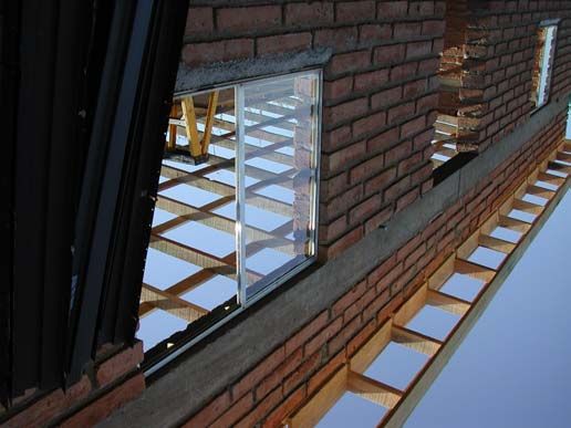
4.1.3 Windows
We have developed a scheme to create a slot in the ladrillos at the window opening to
eliminate the need for the vertical mortar joint or buck-boards and provides a superior
mechanical joint. The method for installing windows is to set the window opening slightly
larger than the window frame (measuring from the frame, not the flange)
The windows used are common wood frame “nail on” style and come with a center flange
on the top, bottom, and sides of the frame. (The window frames themselves are made of
metal. The term “nail-on” refers to the fact they would be nailed to a wooden frame in
normal applications.) Trim the flange from the top and leave the flanges on the sides and
bottom. A 4-4½” grinder is used to cut a narrow vertical slot in the ladrillo at the window
opening for the side flanges of the window to fit in to. This slot is cut 2½” from the outside
face of the ladrillo and as deep as the grinder wheel will permit. The actual windows to be
used in the shelter should be used to determine the width of the window opening.
When the 11th course is in place, 90-degree angle frames to secure the finished window
opening are screwed down, plumbed, and clamped together to provide a vertical
reference to lay the remaining courses of ladrillo against. Having the frame in place
greatly speeds the placing of ladrillo against the window opening. Once the remaining
courses are complete, the frames are removed, and a level is used to mark the remaining
ladrillo where the vertical groove is to be cut. The grinder is used to cut the slot for the
flange along this mark. The reason the first one must be cut before it is laid is because the
grinder cannot be used to cut the ladrillo at the bottom of the opening when it is in place.
Immediately after cutting the slot, the window should be installed in to the slot to be sure it
fits. If needed, the slot can be adjusted. The grinder slot provides an excellent
mechanical retention for the window. With a simple sill built beneath the window, and
caulking all around, the window will be complete (after the dala [bond beam] is in place).
6 Second Edition April, 2002The windows must be in place before the bond beam forms are put up. Using our
methods the windows cannot be installed after the dala has been formed or poured.
4.1.4 The Dala (Bond Beam)
The ladrillo make a reasonable building material but they are hardly strong enough to hold
the shelter in a good wind. The purpose of the dala is to provide a rectangle of steel
reinforced concrete to hold the shelter walls rigid, provide lintels for the doors and
windows, and provide the support base for the roof.
The technique for building the dala is crude but effective. Basically a 1” x 8” wooden form
is built on top of the 20th course of ladrillo. Reinforcing steel (called castillo) is added.
(This lumber will later be ripped in to 1x4 inch strips for use as the stringers fastened to the
top of the rafters, fascia boards and frieze boards.) To support the forms, a conventional
8” stem-wall “clip” typically used in the modern world to hold/space 1“ thick plywood panels
to the top of a footing are used. After the forms are set, 5000 lbs. of concrete is hand lifted
and dumped in the form. A sketch showing what a clip looks like and how the form is set
in the clip is provided in the Construction Details for reference.
While the concrete is still wet J-bolts (for the low side of the shelter) and L-bolts (for the
high side of the shelter) are inserted into the concrete to provide a secure anchor for the
front and rear plates later on. The plates serve as the anchor for the rafters. The shelters
are designed to be 16 inches higher (or 4 courses of ladrillo) on the front to allow for
proper drainage off of the roof. The high side should be on the side of the shelter allowing
another unit of the same size to built adjacent to it at a later date to double the size of the
unit.
The L-bolts on the high side will be 24 inches long and extend above the dala. On this
high side 4 more courses of ladrillo will be set in mortar on top of the dala. This short wall
is called the pony wall. The L-bolts are laid out so they fit in to the mortar joints on the 1st
and 3rd courses of the pony wall. On the other 2 courses the ladrillo must be drilled to
allow the L-bolt to pass through them. The ladrillo are soft enough to be drilled easily with
a ¾ or 1 inch spade bit or masonry bit and a standard drill.
A short sloping wall is built on top of the dala at each end of the shelter to follow the rafter
line down from front to back of the shelter.
4.1.5 Roof
The roof has many key features to provide a strong and sufficiently well insulated cover for
the shelter. The main supports for the roof are 2x4 inch rafters set on 24-inch centers.
Before you conclude this is too weak, keep in mind a 2x4 in Mexico is usually a full 2 by 4
inches, approximately the same strength as a 2x6 in the US. We’ve seen the dimensions
range from 1¾” -2 1/8” by 3¾”-5”.
With the dala complete and the pony wall in place, the roof is ready to be installed. There
are six major components to the roof: plates, rafters, stringers, fascia, frieze boards, foam
insulation and corrugated galvanized steel.
The plates are 2”x6” lumber cut to length and bolted in place on top of the pony wall in
front and on top of the dala in back. Usually there are 2 long pieces at each end and a
shorter piece in the middle. The J-bolts and L-bolts should have been set in the dala in
such a way to insure at least 2 bolts are available for use in bolting down the middle piece
April, 2002 Second Edition 7of the plate. The plates are drilled to match the bolt locations and held in place with ¾ inch
nuts. They are aligned with the outside edge of the dala. The plates extend 2 inches
beyond the end of the dala to allow the end rafter to be set on the outside of the sloped
ladrillo side-wall.
The rafters start as 16-foot sections of 2x4 lumber. They are checked for adequate
strength and straightness (a relative term) and marked for crown direction and sorted by
size. When set on edge, they may vary in height by over an inch. The crown is the
direction of vertical arch when viewed with the board on edge. The rafters must be set in
place with the crown up so the weight of the roof will tend to straighten them out, not
cause them to sag farther downward. They should be sorted by size so you don’t end up
with a high rafter in the middle of the roof, which is very difficult to hide because of the
resulting gap above the fascia board. Something to keep in mind is sorting the rafters by
the dimensions on one end may yield a different result than sorting them by the
dimensions on the other end. Put the most visually appealing ends to the side of the
shelter seen the most.
The rafters are cut to 15’ 8” to allow for 2 inches of fascia (1 inch each, front and back) and
2 inches of overlap from the roofing metal (1 inch each, front and back). The metal roofing
material is a uniform 16 feet in length. The ends of the rafters are pre-cut to make them
plumb in the front and square in the back to minimize exposure to weather and rain runoff.
The rafters are carefully positioned and toenailed in place and then secured with H-3 rafter
ties. Frieze boards are use as blocking to straighten the ends of the rafters. The stringers
form a lattice pattern perpendicular to the rafters. There are 8 rows of stringers from front
to back of the shelter, 5 of which must be precisely located. At this point the dala forms
are cleaned and ripped in to 1x4 material to serve as stringers. There should be enough
form material for all of the stringers and fascia board. The fascia should be cut from the
better-looking stock (another relative term).
The fascia board is put on the ends for the rafters in the front and back of the shelter. The
first stringer (front and back) is laid over the end of the rafters and flush with the outside
edge of the fascia and nailed to the fascia and rafters.
The next stringer in (front and back) is set in place to extend forward of the plate by the
width of the frieze boards so the frieze boards can be pushed up to the stringer and nailed
in place from the top through the stringers for a better weather seal. Essentially, the
stringer will be flush with the outside face of the frieze boards, which also looks nice.
The center of the middle stringer must be 8 feet from the outside edge of the stringer on
the front of the shelter. Because the roofing foam comes in 8-foot sheets, this will
guarantee the seam between sheets will be over a stringer, which looks nicer from the
inside and provides it strength. The remaining 3 stringers (2 on the wide side of the
middle one, and 1 on the narrow side) should be evenly spaced between the middle
stringer and the stringers over the frieze board.
After the stringers you’re ready for foam and steel. Basically the foam is laid down, then
steel is placed on top of it and secured in place with screws with gasket washers to
provide a water seal. Screws are placed on every other ridge of the roofing material along
the length of all 8 stringers. The side lengths of the steel are wrapped over the ends of the
side wall to cover the end rafter and the ends of the plates. About 500 to 800 screws are
used to secure the roof, depending on the type of corrugated metal used. It is good to
have a lot of batteries for your cordless drills.
8 Second Edition April, 20024.1.6 Doors
Door installation can be the most challenging part of the shelter construction. If the door
opening is not built plumb and the correct width by the team building the walls, the door
installation process can be very time consuming.
This is a major challenge. It is not practical to use a frame to build against, because it
can’t be properly braced and held in place without impeding the movement of people and
wheelbarrows through the door opening. Generally we make the opening 41 inches wide.
If the door opening is not vertical a significant amount of shimming may be required.
The doorframe is kept vertical as you are laying courses of ladrillo by using a 4-ft level
against the ladrillo and checking it at each course. The door opening should be checked
every few courses to insure it is remaining 41” in width. Care must be used when grouting
the joints for ladrillos against the door opening so the grout does not push the ladrillo
farther in to the door opening after it has been set in place. Four 12” J-bolts are set in the
mortar joints on each side of the door opening at prescribed levels to be used to bolt the
doorframe against the ladrillo. Don’t forget to put these in. The nuts holding the
buckboards are counter sunk in to the doorframe and any additional bolt length is cut off.
The length of protrusion of the J-bolts is very important. Too shallow and they may not be
long enough to accommodate shimming, too long and the threads may end too soon.
We use solid core 36” x 80” wood doors, 4-inch metal interior frames with snap-on trim,
and smooth metal thresholds with bottom door sweeps. We have found this combination
works best in terms of cost, speed of installation, and durability. This type of door and
frame will likely be waiting for you thanks to the many contributions and donations made
by the Tucson building industry.
Standard door locks and striker plates that come with the frames are used to hold the door
closed. Several tubes of caulk are usually required to seal where each doorframe abuts
ladrillo. Insulation can be stuffed in to the wider openings to reduce the amount of caulk
required.
4.2 The Agua Prieta Environment
Building in Agua Prieta is a unique experience. With proper planning and anticipation, the
work can usually proceed quite well. At times, the lack of the most simple items can be
very inconvenient, or possibly stop the work altogether. We’ve included some notes here
to help you with what to expect and to aid you with the planning process.
4.2.1 How to mix mortar and concrete
Your greatest “friend” in Agua Prieta will be the 8 HP mixers used to mix the concrete and
mortar. At times a crew of 2 can barely make the mud fast enough to keep up with the
masons. It’s hard to imagine having to build the shelter without the mixers available. If
you had to mix by hand, half the crew would do nothing but mix all day and wouldn’t be
able to move their arms at sundown.
What we’re trying to say is “Take care of your mixer”. It’s a harsh, dusty environment to
operate small engines in. Regularly check the oil and don’t run the mixer above the
minimum RPM to keep the drum turning smoothly under load. Running low on oil or
running the mixer for long periods at high RPM will likely render it unavailable for another
group (or your next trip), causing them delays or forcing them to rent another mixer to
April, 2002 Second Edition 9continue, wasting precious funds and time. It can take several hours to locate one having
two wheels and worth renting.
In the course of building the shelter you’ll go through about 5 yards each of mortar sand
and gravel, and countless bags of cement and mortar mix. You’ll be making basic mixes
of concrete and mortar. The quality of the mortar sand in Mexico is notoriously poor.
Sometimes you can’t tell which pile is mortar sand, and which pile is gravel for the
concrete. If the mortar sand has any significant content of pebbles or rocks, it must be
sifted before use, otherwise the resulting mortar will be very difficult to work with. There
are a number of sifting screens in the neighborhood. Find one, borrow it, use it, and plan
on having someone spend most of the day sifting sand.
Concrete is used for the footing, filling the cinder blocks on the stem wall, and for the dala.
Extra or leftovers can be used to make a simple outside pad by the door (throw a few
scraps of rebar in).
Mortar is used to set the cinder block on the footing, to set all ladrillo, and to make the
windowsills.
The mix for concrete is two 5-gallon buckets of water, 1/2 bag of cement (50 kilo bag, 110
lbs.), and 54 large shovels of gravel. The mix for mortar is 1 bucket of water, 1/2 bag of
mortar mix (25 kilo bag, 55 lbs.), and 21 large shovels of mortar sand. Always wet the
wheelbarrow before dumping in the first load of mortar. The same is true for the
mortarboards. This is more important the warmer and drier the weather.
Always start with some water, then at least 10 shovels of gravel or sand, then half a bag of
cement or mortar mix, and repeat until everything is in. Keep the mix wet until you get the
right consistency with the final shovels of dry material. This insures a very thorough mix.
It’s hard to describe the proper consistency with words. For concrete, if it’s too wet it will
flow nicely but it will lose strength because of excessive displacement of the extra water, if
it’s too dry it won’t flow around the reinforcing steel, resulting in voids. It needs to be “just
right”. Similarly for mortar, if it’s too wet it won’t hold it’s shape and will slump under the
weight of the cement block and ladrillo. If it’s too dry it won’t “set” or be sticky enough and
it will be difficult to set blocks correctly with it.
4.2.2 Availability of Water and Power
Through the years water and power are becoming less and less a problem. Power and
water is often available either from the lot you are working or at an adjacent lot.
Community spigots are available throughout the neighborhood as well. The water can
also be used for cleanup, but of course should not be consumed. Always bring a few
hundred feet of hose and extension cords and lots of 5-gallon water buckets. A generator
can be used for power but can be difficult to get across the border and is annoying to listen
to all day. Cordless drills and saws can help too, but when it comes time to grind block or
rip the form material, 120 volts is necessary.
4.2.3 Food, Water and Sanitation
Food and water should be brought with you from Douglas each day. Protection from the
sun in the form of hats and sunscreen should be considered. Pretty much every shelter
has an outhouse, which can be used by the workers. If you’re on the edge of town the
desert can be a nice alternative, but this isn’t very feasible if you’re 5 blocks in. The
10 Second Edition April, 2002outhouses are aromatic, but do the job, at least for #1. For #2 you might want to consider
waiting or heading for the 3 Caminos Restaurant on Hwy 2 (adjacent to Schneiderville).
4.2.4 How They Make the Ladrillos
The production of ladrillo is interesting to watch. Depending on what part of the
neighborhood you are in, there may be several ladrillo yards next door or nearby. The
workers start with clay and mix in sand and sawdust and pile an impossibly heavy load
into their wheelbarrows. They use a simple wooden form to make 2 to 3 ladrillos at a time
on the ground. They leave them to dry for a day. The next day they come back and stand
them on their sides, and later stack them up on their sides loosely, about three high.
When they’re fully dry, the ladrillos are stacked in to a kiln containing about 1,000 to 7,000
ladrillos. The outside is covered with a mix of mud and manure to seal it and 2 to 3
channels are left open at the bottom. The ladrillo are carefully stacked inside to allow
airflow between them.
Pallets or other scrap wood is used to make a fire in the channels at the bottom of the kiln.
The fire is kept hot for 30 hours, generally consuming around 150 wooden pallets. The
kiln is left to cool for a few days and when it is disassembled the resulting burnt adobe
bricks, or ladrillo, are ready to sell for about 3½ pesos, or 40 cents, apiece.
They start out the color of brown mud and become a pinkish orange after firing.
Unfired adobes are cheaper and can be used for construction also, but they must be
sealed against the elements. They will eventually wash away to nothing if left exposed to
the rain over a short period of time. Several examples of this can be seen in the
neighborhood.
The ladrillo are risky to make in the coldest part of the winter. If they are allowed to freeze
before they dry initially it will destroy the structural integrity of the ladrillo and they will
crumble after firing. A light frost may only slightly damage them. If it’s particularly cold, the
supply of quality ladrillo can be limited. It’s common for the temperature to drop to the low
20’s during January because of the high elevation (4000’) and extremely low humidity.
Dew points in the single digits are not uncommon. A 35-degree temperature range from
low to high is typical.
When buying ladrillos for a job, check the stock. Holding the ladrillo in both hands, break
the ladrillo in half over the sharp corner of a wall or fence. Hold on to both halves after it
breaks. The break should be clean and even and the ladrillo should not crumble in your
hands. The inside should be light brown to tan, and the rectangular center should be a
darker brown.
Watch out for the size of the ladrillo. The width should be 7”. A length of 13 ½” to 14” will
work best. Sample a few for uniformity of dimensions.
4.2.5 What to Bring with You
There are a number of things you may want to bring with you depending on the time of
year, the group you’re with, and the length of your stay. The church provides floors for
sleeping, tables, chairs, kitchen items for preparing meals, dishes/flatware, and 2 showers
and bathrooms.
April, 2002 Second Edition 11Air mattresses, cots or sleeping pads are handy for a comfortable night’s sleep. Basic
toiletry items and towels are essential. There’s plenty of room for parking motor homes
adjacent to the church, but no hook-ups are available.
Many groups bring clothes, food, toys, school supplies, and other items to take across the
border to distribute to residents of the neighborhoods in Agua Prieta. One note here:
Mexican border police may stop you from bringing items across if you try to bring too
much in one vehicle. A good suggestion is to take a little at a time and split the load up
over a number of trips. We’ve never had a problem when using this technique.
The church provides many of the tools required for building the shelter. Other groups
have purchased these tools and then donated them to the “camp”. In general, the more
tools you can bring with you the better. In the construction details we list the tools required
for each stage of construction of the shelter. If you know which stages of construction you
will be involved in, review the lists of tools required and bring as many of the tools as you
can.
Marking your personal tools with a unique marking can make it handy to sort out the tools
at the end of the workday. It’s surprising how all the shovels, hammers, and trowels will
start to look alike.
We have had a few isolated instances of tools disappearing from the work sites. While
this has not been a major problem, it’s a good idea to keep an eye on the tools. Don’t
leave any tools at the site at the end of the workday. If any valuable materials or tools
must be left behind, they should be secured inside an occupied dwelling.
Many times the process can go quicker if more tools are available. For instance, when the
metal roofing material is being attached to the stringers, it’s handy to have 5 cordless drills
to use as screwdrivers at once. The job can be done with less, but having more will make
the work go more quickly.
12 Second Edition April, 20025 Construction Details
5.1 Building the Foundation
Tools required:
• transit (builder’s level)
• 100 and 30ft. tape measures
• square and round end shovels
• pickaxes
• string
• 12 concrete stakes or other large stakes
• concrete mixer
• trowels
• mortar boards
• rebar bender/cutter or hacksaw or chop saw
• small sledge hammer
• rebar tie tool and ties or wire and wire cutter/pliers
• float
• wheelbarrows
• general tool kit including spark plug wrench for the mixer
Materials required:
• eight 50 kg bags of concrete mix
• three 25 kg bags of mortar mix
• 75 8”x8”x16” cinder blocks plus extra 8”x4” or 8”x8” blocks if a step is required
• gravel/sand for concrete
• mortar sand
• gasoline/oil for concrete mixer
• seven 40 ft pieces of #4 (½ inch) rebar
• 50 plastic chairs to elevate the rebar in the trench
5.1.1 Site layout
Deciding where to build the shelter is the first decision to be made. Generally there will be
some discussion with the future owners as to the exact location and any special features
required. Often, when a shelter is proposed for a lot, a shack or similar structure is on the
lot and generally blocks the best location to place the new shelter. The options existing at
this point include:
• Place the shelter in a less desirable location
• Reorient the existing or new shelter
• Relocate the family for the duration of construction and have the shack removed
Choose as flat an area on the lot as possible. The maximum drop in elevation from corner
to corner of the footing is 8” without adding a step to the footing. If the elevation change is
greater than 6”, a step will be required (see “footing step” detail).
April, 2002 Second Edition 13Set the initial position for the 4 corners of the shelter using the 100-ft tape measure and
the concrete stakes. Look around to see if any access problems will exist. It will be nice if
you can get a wheelbarrow around the entire shelter or across the footings with a plank.
The speed-leads will require about 4 feet of clearance in both directions from each corner
to be anchored in the ground properly.
Set the shelter position as a rectangle 13’4” by 33’4”. You can get the corners reasonably
square using the 3/4/5 right triangle method. In this case 12’ by 16’ sides with a 20’
diagonal can be used effectively. When you think you’re reasonably close, you can verify
how square the shelter is by checking the length of the 2 diagonals measured from
opposite corners. If the distance is the same the rectangle is square. The diagonal
distances should be 35’10¾” and no more than 1 inch different from each other. Take
care in making these measurements, as your errors will accumulate as the shelter
progresses. A few minutes invested here will be rewarded with a better shelter and less
work later. Set a concrete stake firmly at each corner.
In some instances, you may be able to pre-stake a shelter footing and have it dug by the
future owner or a local laborer. Builders are encouraged to take advantage of this
opportunity whenever possible, as it can save a considerable amount of time and manual
labor. However, a few things need to be considered before handing over the pick and
shovel and leaving the new site.
First, it is recommended that the corner stakes used be a minimum 24” long and driven
into the ground so only 4” or so is left sticking above the ground. The reason for driving
them so deep is to keep them from coming out, being bent over or tilted out of alignment
while the footing corners are being dug. It helps to ask the digger not to remove them, too.
Second, to assist the digger, place another stake (outside the building wall area) about 4
¼” diagonally from the corner stake. These do not have to be hammered in very deep but
enough to remain stable while digging the footing. Set an additional one in the same
place for each corner. When you finish, there will be four stakes in addition to the corner
stakes and they will aligned 3 – 4 inches outside of and parallel to the future building wall.
Each of the second stakes will coincide with the outside edge of the footing. Next, wrap a
string around the outside set of stakes to identify the outside edge of the footing to be dug.
Provide the digger with a tape measure or mark a stick at 14” that he can use to measure
the width of the footing, and another marked at 8” to measure the depth of the footing.
If the corner stakes are missing when you return you can re-determine their location by
using an “outside squaring” technique. See Figure 1 - Outside Squaring Technique. First,
locate two corners inside the long footing 33’ 4” apart and set a stake for each of the two
corners. Measure an additional 13’ 4” beyond a corner stake. Then measure 13’ 4” from
the stake at a right angle in the bottom of the shorter footing. Using the same method as
the 12’, 16’, 20’ triangle shown in Figure 1, close the 13’ 4” triangle with a diagonal
measurement of 18’ 10 ¼” and set a stake for the third corner. Do the same thing on the
other end of the shelter footing. Double check the distance between all corner stakes and
then set the 8 stakes shown in Figure 2 - Site Layout.
14 Second Edition April, 2002FOOTING LINE
STACKED LADRILLO
CROSS CHECK
DIMENSION
13'-4"
18
'-1
0
1/
4"
TRIANGLE @ 12', 16', 20'
BUILDING CORNER PIN - TYPICAL
33'-4" 13'-4"
• Figure 1 - Outside Squaring Technique
In some cases, there may be an obstruction in the way that does not permit squaring both
ends of the footings in this manner. If this is the case, there isn’t much else to do in the
field but just do the best you can to locate the missing corners as accurately as possible.
5.1.2 Determining the footing elevation and marking for excavation
Using 8 concrete stakes, extend each of the 4 sides of the shelter approximately 4 feet
past the stakes marking the corners of the shelter. See Figure 2 - Site Layout. This is
done because the original 4 shelter wall corner stakes will have to be removed to do the
excavation for the footing. Wrapping a string tightly around the outside of the new stakes
will mark the outside walls of the shelter. This string, set to the correct height later, will
provide the guide to align and lay the cinder blocks for a level and straight stem wall.
April, 2002 Second Edition 15TRIANGLE @ 12', 16', 20'
FOOTING LINE
BUILDING LINE
4'-0"
13'-4"
" 35'-
3/4 1
5'- 10 CROSS CHECK 0 3/4"
3
DIMENSION
4'-0"
BUILDING WALL PIN - TYPICAL
4'-0" 33'-4" 4'-0"
• Figure 2 - Site Layout
The transit is used to determine the relative elevation of the corners and determine the
optimal elevation of the footing and whether a step will be required in the footing.
Generally the high and low spots will be at opposite corners, but check to make sure this is
the case. If it is not, use the actual high and low spots instead of the corners. If the delta
between the high and low spots is more than 6 inches, a step will be required. (If a step is
not required, high-5’s at this point are appropriate.)
The goal is to have a footing 8” thick and 14” wide. If possible, choose an elevation having
the top of the footing approximately at grade level at the low corner. This will minimize the
digging required. The total trench is 93’ long, every inch matters.
16 Second Edition April, 20027"
1/2" - 3/4"
INSIDE WALL
1"
8" X 8" X 16" CONCRETE
LADRILLO BLOCK STEM WALL
GROUND LEVEL
14" MAX.
8" MIN.
8" 8" X 14" FOOTING
REBAR CHAIR
(2) 1/2" REBAR 1'-2"
• Figure 3 - Footing Detail
Before removing the original 4 stakes marking the actual corners of the shelter, use the
strings as a guide and mark (with paint or otherwise) a line 3” outside the string and 11”
inside the string all the way around the shelter. This should provide a minimum 14” wide
footing which when completed will extend at least 3” beyond each side of the stem wall.
After marking the trench outline, remove the string.
Now you’re ready to start digging. Be careful to keep the edges of the trench as vertical
as possible. Sloppy work here such as a caved-in side will result in wasted concrete in the
trench. Check the depth frequently using the transit. If the perimeter string is leveled, it
can be used as an easy reference for depth of the trench. It is important not to dig too
deep. If dirt is filled back in to obtain the proper depth it must be compacted, or it will result
in weakness later on. Clean the trench of any loose debris and square the bottom of the
footing the best you can. See Figure 3 - Footing Detail for a picture of what the trench
should look like.
Remember, the whole idea behind the stem wall is to keep the ladrillo at least 2
inches above the ground and located where standing or running water or wet dirt
can not come in contact with them. To accomplish this, the concrete stem wall has to
extend above the ground a minimum 2 inches.
5.1.3 Continuous Footing
If the lot has a grade differential of over 6 inches measured from the corners of the
foundation, two options are available. The first option is to continue to dig the footing
bottom level under the four wall alignments. This results in a footing starting out 8 inches
deep and may end up being over 14 inches deep. An 8-inch thick footing is still poured for
the entire foundation but because of the deeper foundation several courses of block are
required in order to rise above ground level. Since building funds are generally tight, the
April, 2002 Second Edition 17cost of the additional block and mortar can be significant. Also, digging the footing an
additional 8 inches deep around half of the foundation takes critical time and energy. In
addition, until you have picked up an 8 x 8 x 16 block made in Mexico and lean down and
into the footing with it for the first course, can you say, “now this is certainly an experience
waiting to be forgotten”.
Being fair, though, some believe a footing and stem built this way provides the best
continuity and stability for above ground wall construction.
Another option is to “step” the footing. Stepping provides a way to minimize the dig and
keep the number of block needed to stay above the ground within budget.
5.1.4 Stepped Footing
This is not the ideal situation to be in but if the ground level between corners of the
foundation is greater than 6 inches, a step in the footing should be considered. If possible,
try re-orienting the structure on the site to avoid having to step the footing, which then
requires more than one level of block for the stem.
The step will be either 4 inches high or 8 inches high (or two 4 inch steps spaced out)
depending on the grade difference of the lot. In either case the process to make the step
is the same except for the height of the first course of ladrillo being laid.
Let’s assume the change in grade across the foundation is 6 inches. We know a step is
not required, (8” block height minus 6” grade leaves 2” of block above the surface). Once
a difference of 7 inches to 10 inches occurs, a 4-inch step is necessary in order to keep
the ladrillo out of the dirt by at least 2 inches. See Figure 4 - 4" Step Diagram for the
layout required for a 4-inch step. Greater than 10 inches requires two 4 inch steps or an
8-inch and so on. See Figure 5 - 8" Step Diagram for the layout required for an 8-inch
step.
CORNER 1/2" REBAR LOT SURFACE (GRADE)
REBAR
2"
TEMPORARY FORM
8" X 8" X 16"
8" X 4" X 16"
BLOCK
FOOTING HEIGHT OF STEP EQUALS
HEIGHT BLOCK HEIGHT + MORTAR CONCRETE
STAKES JOINT FOOTING
• Figure 4 - 4" Step Diagram
18 Second Edition April, 2002LOT SURFACE (GRADE)
TEMPORARY FORM
2"
8" X 8" X 16"
BLOCK STEM
HEIGHT OF STEP EQUALS
BLOCK HEIGHT + MORTAR CONCRETE
JOINT FOOTING
• Figure 5 - 8" Step Diagram
Location of the step is determined by digging 8 inches deep at the lowest point of the
lot/footing. (Another way is to set up a builder’s level/transit and “shoot” grades and mark
the points ahead of time.) Keep the bottom of the footing level as you continue to dig
along the footing line. With the bottom level, the trench will eventually get deeper the
further you dig along the line and away from the lowest point. When you get to a point
where the footing depth is 12 inches, this is approximately where the step (up) will be
placed. Roughly mark this location and dig at least two feet past. Now go back to the spot
where digging the footing started and go the other direction until the bottom of the footing
is also 12 inches below ground level, roughly mark the location and continue at least 2 feet
past.
As well as 12 inches deep, the footing should about 14 inches wide at the step area. Two
pieces of lumber 2” x 4½” x 14 inches should be cut. To determine the actual location of
the step, determine the future building wall corners in the footing just dug. Since Mexican
made cinder block is generally 15 ¾ to 16 inches long, we calculate the distance
assuming a 16¼ -inch module.
From the building wall corner to the BACK of the 2 x step material, determine the distance
needed to accommodate 16-inch long stem wall block and add two inches. Drive two
pieces of rebar into the footing about 4 inches from the each side and tie-wire the 2 x
board to the rebar with the top of the board 12 ½ inches from the bottom of the footing.
Essentially, the bottom of the 2 x board should be level with the ground of the lowest point
of the footing which should be where you first started digging.
When the footing is poured, be careful not to move the board much. The weight of the
footing behind the board will put some pressure on the form, so make sure it is braced
well. For best results, remove the board after the concrete has set-up but is still wet.
Once again, identify the building corner, re-measure for block layout and adjust the step if
there is not enough room to place the row of block by using a trowel or shovel to shave the
face of the stepped-up footing. More than enough distance to lay block is fine. The
spacing will be made up on the second course.
5.1.5 Setting stakes for the footing height
In order to insure the correct height for the footing, rebar stakes are set approximately
every 4’ in the trench. Make the stakes by cutting twenty-five 14” pieces of rebar. The
transit is used to set the correct elevation for each corner stake about 8” above the bottom
of the footing. After the corner rebar are set in the footings, a string can then be run
between the top of the corner stakes and be used as a guide for the elevation of the
stakes set in between. This process goes relatively quickly. Care should be taken to
April, 2002 Second Edition 19You can also read