ALBEDOMETER OWNER'S MANUAL - Model SP-722-SS - Apogee Instruments
←
→
Page content transcription
If your browser does not render page correctly, please read the page content below
OWNER’S MANUAL

        ALBEDOMETER
                    Model SP-722-SS
                         Rev: 7-Sept-2021

APOGEE INSTRUMENTS, INC. | 721 WEST 1800 NORTH, LOGAN, UTAH 84321, USA
 TEL: (435) 792-4700 | FAX: (435) 787-8268 | WEB: APOGEEINSTRUMENTS.COM

                Copyright © 2021 Apogee Instruments, Inc.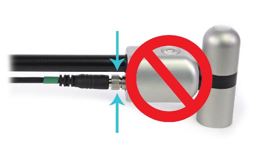
TABLE OF CONTENTS
CERTIFICATE OF COMPLIANCE

EU Declaration of Conformity

This declaration of conformity is issued under the sole responsibility of the manufacturer:

         Apogee Instruments, Inc.
         721 W 1800 N
         Logan, Utah 84321
         USA

for the following product(s):

Models: SP-722
Type: Albedometer

The object of the declaration described above is in conformity with the relevant Union harmonization legislation:

2014/30/EU        Electromagnetic Compatibility (EMC) Directive
2011/65/EU        Restriction of Hazardous Substances (RoHS 2) Directive
2015/863/EU       Amending Annex II to Directive 2011/65/EU (RoHS 3)

Standards referenced during compliance assessment:

EN 61326-1:2013 Electrical equipment for measurement, control and laboratory use – EMC requirements
EN 50581:2012 Technical documentation for the assessment of electrical and electronic products with respect to
                the restriction of hazardous substances

Please be advised that based on the information available to us from our raw material suppliers, the products
manufactured by us do not contain, as intentional additives, any of the restricted materials including lead (see
note below), mercury, cadmium, hexavalent chromium, polybrominated biphenyls (PBB), polybrominated
diphenyls (PBDE), bis (2-ethylhexyl) phthalate (DEHP), butyl benzyl phthalate (BBP), dibutyl phthalate (DBP), and
diisobutyl phthalate (DIBP). However, please note that articles containing greater than 0.1 % lead concentration
are RoHS 3 compliant using exemption 6c.

Further note that Apogee Instruments does not specifically run any analysis on our raw materials or end products
for the presence of these substances, but we rely on the information provided to us by our material suppliers.

Signed for and on behalf of:
Apogee Instruments, September 2021

Bruce Bugbee
President
Apogee Instruments, Inc.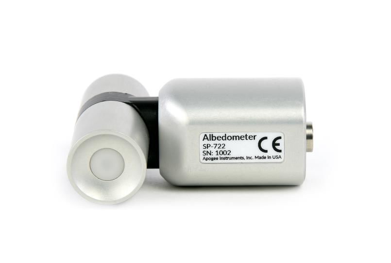
INTRODUCTION

Solar radiation at Earth’s surface is typically defined as total radiation across a wavelength range of 280 to 4000
nm (shortwave radiation). Total solar radiation, direct beam and diffuse, incident on a horizontal surface is defined
as global shortwave radiation, or shortwave irradiance (incident radiant flux), and is expressed in Watts per square
meter (W m-2, equal to Joules per second per square meter). Albedo is the ratio of reflected to incoming global
shortwave radiation and varies from zero to one. Materials with a high albedo reflect most solar radiation, and
materials with low albedo absorb most solar radiation.

An albedometer is an instrument designed to measure albedo, and consists of two pyranometers, which separately
measure incoming and reflected shortwave irradiance. The SP-722 upward- and downward-facing pyranometers
are blackbody thermopile pyranometers sensitive to most of the solar spectrum, thus eliminating spectral errors
associated with silicon-cell pyranometers. The upward-facing pyranometer is designed to measure incoming global
shortwave irradiance and combines an acrylic diffuser with the blackbody detector. The downward-facing
pyranometer is designed to measure reflected shortwave irradiance from terrestrial surfaces and combines a
sintered quartz diffuser with the blackbody detector. Both sensors have calibrations traceable to Class A blackbody
thermopile pyranometers traceable to the world radiation reference in Davos, Switzerland. Specifications for both
models compare favorably to specifications for World Meteorological Organization (WMO) moderate and good
quality classifications and specifications for International Organization of Standardization (ISO) Class C and Class B
classifications.

Typical applications of pyranometers include incoming and reflected shortwave radiation measurement in
agricultural, ecological, and hydrological weather networks and solar panel arrays. Albedo measurements indicate
the reflectivity of materials with respect to shortwave radiation, and are used to study climate and weather,
monitor bifacial solar panels, and understand heat retention in urban and architectural settings.

Apogee Instruments model SP-722 albedometers are two-component instruments, with individual upward- and
downward-looking pyranometers. Each albedometer consists of a thermopile detector and diffuser mounted in an
anodized aluminum housing. Each radiometer is heated (if desired, heaters can be turned on and off) to minimize
the effects of dew, frost, snow, and ice on the filter and sensor head. Analog signals from each albedometer are
measured with an onboard voltmeter and converted to a digital value. That value can then be accessed via a
Modbus RTU interface over an RS-232 or RS-485 serial connection. This eliminates the need for multiple analog
datalogger channels to make the four-component measurement of net radiation. SP-722 net radiometers are small
and lightweight to facilitate rapid and simple mounting.
SENSOR MODELS
This manual covers the Modbus RTU communication protocol, albedometer model SP-722 (in bold below).
Additional models are covered in their respective manuals.
Model Signal
SP-722 Modbus
SP-710 Analog
Apogee Instruments’ two-component albedometer consists of an upward-looking and downward-looking
pyranometer (to measure shortwave radiation. Both individual sensors are available as stand-alone sensors.
Upward-looking Pyranometer
Downward-looking Pyranometer
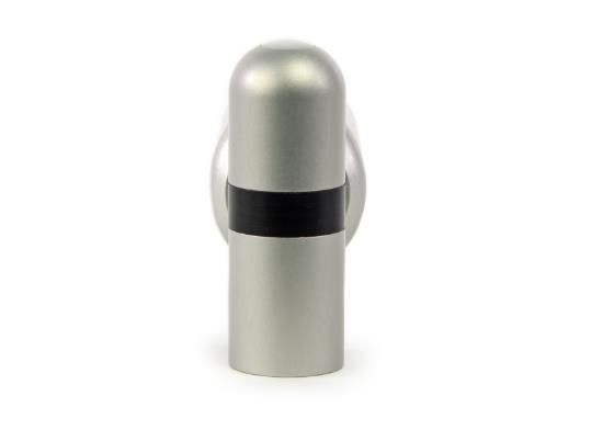
A sensor’s model number and serial number
are located on the bottom of the sensor. If
you need the manufacturing date of your
sensor, please contact Apogee Instruments
with the serial number of your sensor.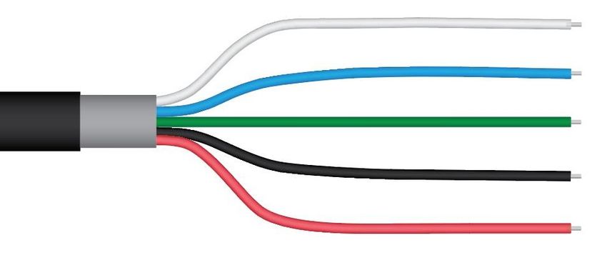
SPECIFICATIONS
                                           SP-722-SS (Upward-looking)                SP-722-SS (Downward-looking)
 ISO 9060:2018                                       Class C                                      N/A

 Power Supply                                                             5.5 to 24 V

                                                                      Heaters off: ≈ 5 mA
 Current Draw
                                                                      Heaters on: ≈ 31 mA

 Calibration Uncertainty at 1000 W m-2              Less than 3 % (see Calibration Traceability below)

 Measurement Range                                       0 to 2000 W m-2 (shortwave irradiance)

 Measurement Repeatability                                               Less than 1 %

 Long-term Drift (Non-stability)                                  Less than 2 % per year

 Non-linearity                                                           Less than 1 %

 Field of View                                        180°                                       150°

 Spectral Range (wavelengths where
                                                 385 to 2105 nm                             370 to 2240 nm
 response is 50% of maximum)
                                                Less than 30 W m-2                    Less than 20 W m-2 for angles
 Directional (Cosine) Response
                                                at 80° solar zenith                         between 0 and 60°

 Temperature Response                                          Less than 5 % from -15 to 45 C

                                         Less than 2 W m-2; Less than 10 W       Less than 1 W m-2; Less than 5 W m-2
 Zero Offset A
                                                    m-2 (heated)                              (heated)

 Zero Offset B                                                         Less than 5 W m-2

 Uncertainty in Daily Total                                              Less than 5 %

 Operating Environment                                   -50 to 80 C; 0 to 100 % relative humidity

 Heater                                  390 Ω, 30.8 mA current draw and 370 mW power requirement at 12 V DC

 Dimensions                                          66.5 mm height, 74.4 mm length, 33 mm width

 Mass                                                                        247 g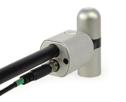
Calibration Traceability

The pyranometers on Apogee Instruments model SP-722 albedometers are calibrated through side-by-side
comparison to the mean of four Apogee model SP-510 transfer standard pyranometers (shortwave radiation
reference for upward-looking pyranometer on albedometer) or to the mean of four Apogee model SP-610 transfer
standard pyranometers (shortwave radiation reference for downward-looking pyranometer on albedometer)
under high intensity discharge metal halide lamps. The transfer standard pyranometers are calibrated through
side-by-side comparison to the mean of at least two ISO-classified reference pyranometers under sunlight (clear
sky conditions) in Logan, Utah. Each of four ISO-classified reference pyranometers are recalibrated on an
alternating year schedule (two instruments each year) at the National Renewable Energy Laboratory (NREL) in
Golden, Colorado. NREL reference standards are calibrated to the World Radiometric Reference (WRR).
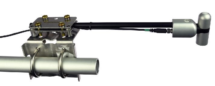
DEPLOYMENT AND INSTALLATION
An Apogee Instruments model AM-500 or the AM-240 mounting bracket can be used to mount the albedometer to
a cross arm.
AM-500
AM-240
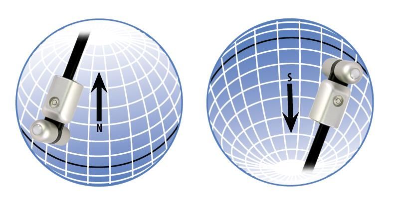
To minimize azimuth error, the sensor should be mounted with the cable pointing toward true north in the
northern hemisphere or true south in the southern hemisphere. Azimuth error is typically less than 0.5 %, but it is
easy to minimize by proper cable orientation.
In addition to orienting the cable to point toward the nearest pole, the sensor should also be mounted such that
obstructions (e.g., weather station tripod/tower or other instrumentation) do not shade the sensor. Once
mounted, the green caps should be removed from the sensor. The green caps can be used as a protective
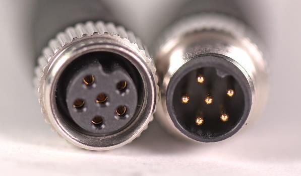
covering for the sensor when it is not in use.CABLE CONNECTORS
Apogee sensors offer cable connectors to simplify the
process of removing sensors from weather stations
for calibration (the entire cable does not have to be
removed from the station and shipped with the
sensor).
The ruggedized M8 connectors are rated IP68, made
of corrosion-resistant marine-grade stainless-steel,
and designed for extended use in harsh
environmental conditions.
Cable connectors are attached directly to the head.
Instructions
Pins and Wiring Colors: All Apogee connectors
have six pins, but not all pins are used for every
sensor. There may also be unused wire colors
inside the cable. To simplify datalogger
connection, we remove the unused pigtail lead
colors at the datalogger end of the cable.
If a replacement cable is required, please contact
Apogee directly to ensure ordering the proper
pigtail configuration. A reference notch inside the connector ensures
proper alignment before tightening.
Alignment: When reconnecting a sensor, arrows
on the connector jacket and an aligning notch
ensure proper orientation.
Disconnection for extended periods: When
disconnecting the sensor for an extended period
of time from a station, protect the remaining half
of the connector still on the station from water Finger-tighten firmly
and dirt with electrical tape or other method.
Tightening: Connectors are designed to be firmly
finger-tightened only. There is an o-ring inside
the connector that can be overly compressed if a
wrench is used. Pay attention to thread
alignment to avoid cross-threading. When fully
tightened, 1-2 threads may still be visible.
*NOTE: To avoid damaging the pins inside the
connector, finger-tighten the connector by only
turning the metal nut (see blue arrows). Do not
tighten by turning the black cable.OPERATION AND MEASUREMENT
The SP-722 has a Modbus output, where the two components of shortwave radiation and albedo are returned in
digital format. Measurement of SP-722 albedometers requires a measurement device with a Modbus interface
that supports the Read Holding Registers (0x03) function.
Wiring
White: RS-232 RX / RS-485 Positive
Blue: RS-232 TX / RS-485 Negative
Green: Select (Switch between RS-232 and RS-485)
Black: Ground
Red: Power +12 V
The Green wire should be connected to Ground to enable RS-485 communication, or it should be connected to 12
V power for RS-232 communication. Text for the White and Blue wires above refers to the port that the wires
should be connected to.
Sensor Calibration
All Apogee Modbus albedometers (model SP-722) have sensor-specific calibration coefficients determined during
the custom calibration process. Coefficients are programmed into the sensors at the factory.
Modbus Interface
The following is a brief explanation of the Modbus protocol instructions used in Apogee SP-722 net radiometers.
For questions on the implementation of this protocol, please refer to the official serial line implementation of the
Modbus protocol: http://www.modbus.org/docs/Modbus_over_serial_line_V1_02.pdf (2006) and the general
Modbus protocol specification: http://www.modbus.org/docs/Modbus_Application_Protocol_V1_1b3.pdf (2012).
Further information can be found at: http://www.modbus.org/specs.php
Overview
The primary idea of the Modbus interface is that each sensor exists at an address and appears as a table of values.
These values are called Registers. Each value in the table has an associated index, and that index is used to identify
which value in the table is being accessed.Sensor addresses Each sensor is given an address from 1 to 247. Apogee sensors are shipped with a default address of 1. If using multiple sensors on the same Modbus line, the sensor’s address will have to be changed by writing the Slave Address register. Register Index Each register in a sensor represents a value in the sensor, such as a measurement or a configuration parameter. Some registers can only be read, some registers can only be written, and some can be both read and written. Each register exists at a specified index in the table for the sensor. Often this index is called an address, which is a separate address than the sensor address, but can be easily confused with the sensor address. However, there are two different indexing schemes used for Modbus sensors, though translating between them is simple. One indexing scheme is called one-based numbering, where the first register is given the index of 1, and is thereby accessed by requesting access to regis er 1. The other indexing scheme is called zero-based numbering, where the first register is given the index 0, and is thereby accessed by requesting access to register 0. Apogee Sensors use zero-based numbering. However, if using the sensor in a system that uses one-based numbering, such as using a CR1000X logger, adding 1 to the zero-based address will produce the one-based address for the register. Register Format: According to the Modbus protocol specification, Holding Registers (the type registers Apogee sensors contain) are defined to be 16 bits wide. However, when making scientific measurements, it is desirable to obtain a more precise value than 16 bits allows. Thus, several Modbus implementations will use two 16-bit registers to act as one 32-bit register. Apogee Modbus sensors use this 32-bit implementation to provide measurement values as 32-bit IEEE 754 floating point numbers. Apogee Modbus sensors also contain a redundant, duplicate set of registers that use 16-bit signed integers to represent values as decimal-shifted numbers. It is recommended to use the 32-bit values, if possible, as they contain more precise values. Communication Parameters: Apogee Sensors communicate using the Modbus RTU variant of the Modbus protocol. The default communication parameters are as follows: Slave address: 1 Baudrate: 19200 Data bits: 8 Stop bits: 1 Parity: Even Byte Order: Big-Endian (most significant byte sent first) The baudrate and slave address are user configurable. Valid slave addresses are 1 to 247. Since the address 0 is reserve as the broadcast address, setting the slave address to 0 will actually set the slave address to 1. (This will also reset factory-calibrated values and should NOT be done by the user unless otherwise instructed.)
Read only registers (function code 0x3).

 Float Registers
                    0                          Incident calibrated output watts
                    1
                    2                         Reflected calibrated output watts
                    3
                    4                            Incident detector millivolts
                    5
                    6                            Reflected detector millivolts
                    7
                    8                            Albedo (reflected/incident)
                    9
                   10                              Reserved for future use
                   11
                   12                                 "device status
                   13                      (1 means device is busy, 0 otherwise)"

                14                                     firmware version
                15
 Integer Registers
                                                Incident calibrated output watts
                   44
                                             (shifted one decimal point to the left)
                                               Reflected calibrated output watts
                   45
                                             (shifted one decimal point to the left)
                                                   Incident detector millivolts
                   46
                                           (shifted three decimal points to the left)
                                                  Reflected detector millivolts
                   47
                                           (shifted three decimal points to the left)
                                                   Albedo (reflected/incident)
                   48
                                             (shifted one decimal point to the left)
                   49                                Reserved for future use
                                                           device status
                   50
                                             (1 means device is busy, 0 otherwise)
                                                        firmware version
                   51
                                             (shifted one decimal point to the left)
Read/Write registers (function codes 0x3 and 0x10).
Float Registers
20
slave address
21
22
model number*
23
24
serial number*
25
26 Baudrate (0 = 115200, 1 = 57600, 2 = 38400, 3 = 19200, 4 = 9600, any other
27 number = 115200)
28
parity (0 = none, 1 = odd, 2 = even)
29
30
number of stopbits
31
32
incident multiplier*
33
34
incident offset*
35
36
reflected multiplier*
37
38
reflected offset*
39
40
running average
41
42
heater on/off
43
Integer Registers
54 slave address
55 model number*
56 serial number*
baudrate (0 = 115200, 1 = 57600, 2 = 38400, 3 = 19200, 4 = 9600, any other
57
number = 115200)
58 parity (0 = none, 1 = odd, 2 = even)
59 number of stopbits
60 incident multiplier (shifted two decimal points to the left)*
61 Incident mV offset (shifted two decimal points to the left)*
62 reflected multiplier (shifted two decimal points to the left)*
63 Reflected mV offset (shifted two decimal points to the left)*
64 Running average
65 Heater on/off
*Registers marked with an asterisk (*) cannot be written to unless a specific procedure is followed. Contact
Apogee Instruments to receive the procedure for writing these registers.Packet Framing: Apogee Sensors use Modbus RTU packets and tend to adhere to the following pattern: Slave Address (1 byte), Function Code (1 byte), Starting Address (2 bytes), Number of Registers (2 bytes), Data Length (1 byte, optional) Data (n bytes, optional) Modbus RTU packets use the zero-based address when addressing registers. For information on Modbus RTU framing, see the official documentation at http://www.modbus.org/docs/Modbus_Application_Protocol_V1_1b3.pdf Example Packets: An example of a data packet sent from the controller to the sensor using function code 0x3 reading register address 0. Each pair of square brackets indicates one byte. [Slave Address][Function][Starting Address High Byte][Starting Address Low Byte][No of Registers High Byte][No of Registers Low Byte][CRC High Byte][CRC Low Byte] 0x01 0x03 0x00 0x00 0x00 0x02 0xC4 0x0B An example of a data packet sent from the controller to the sensor using function code 0x10 writing a 1 to register 26. Each pair of square brackets indicates one byte. [Slave Address][Function][Starting Address High Byte][Starting Address Low Byte][No of Registers High Byte][No of Registers Low Byte][Byte Count][Data High Byte][Data Low Byte][Data High Byte][Data Low Byte][CRC High Byte][CRC Low Byte] 0x01 0x10 0x00 0x1A 0x00 0x02 0x04 0x3f 0x80 0x00 0x00 0x7f 0x20.
MAINTENANCE AND RECALIBRATION
Moisture or debris on the filters is a common cause of errors. The upward-looking sensor has a domed housing for
improved self-cleaning from rainfall, but materials can accumulate on the diffuser or window (e.g., dust during
periods of low rainfall, salt deposits from evaporation of sea spray or sprinkler irrigation water) and partially block
the optical path. Materials can also accumulate on the downward-looking detector. Dust or organic deposits are
best removed using water or window cleaner and a soft cloth or cotton swab. Salt deposits should be dissolved
with vinegar and removed with a soft cloth or cotton swab. Never use an abrasive material or cleaner on the
diffuser.

Although Apogee sensors are very stable, nominal accuracy drift is normal for all research-grade sensors. To
ensure maximum accuracy, we generally recommend sensors are sent in for recalibration every two years,
although you can often wait longer according to your particular tolerances.

Upward-Looking Pyranometer (Shortwave Radiation)

The Clear Sky Calculator (www.clearskyccalculator.com) can be used to determine the need for pyranometer
recalibration. It determines total shortwave radiation incident on a horizontal surface at any time of day at any
location in the world. It is most accurate when used near solar noon in spring and summer months, where
accuracy over multiple clear and unpolluted days is estimated to be ± 4 % in all climates and locations around the
world. For best accuracy, the sky must be completely clear, as reflected radiation from clouds causes incoming
radiation to increase above the value predicted by the clear sky calculator. Measured values of total shortwave
radiation can exceed values predicted by the Clear Sky Calculator due to reflection from thin, high clouds and
edges of clouds, which enhances incoming shortwave radiation. The influence of high clouds typically shows up as
spikes above clear sky values, not a constant offset greater than clear sky values.

To determine recalibration need, input site conditions into the calculator and compare total shortwave radiation
measurements to calculated values for a clear sky. If sensor shortwave radiation measurements over multiple days
near solar noon are consistently different than calculated values (by more than 6 %), the sensor should be cleaned
and re-leveled. If measurements are still different after a second test, email calibration@apogeeinstruments.com
to discuss test results and possible return of sensor(s).
Homepage of the Clear
Sky Calculator. Two
calculators are available:
One for pyranometers
(total shortwave
radiation) and one for
quantum sensors
(photosynthetic photon
flux density).

Clear Sky Calculator
for pyranometers.
Site data are input in
blue cells in middle of
page and an estimate
of total shortwave
radiation is returned
on right-hand side of
page.
TROUBLESHOOTING AND CUSTOMER SUPPORT
Independent Verification of Functionality

If the sensor does not communicate with the datalogger, use an ammeter to check the current drain. It should be
near 37 mA when the sensor is powered. Any current drain significantly greater than approximately 37 mA
indicates a problem with power supply to the sensors, wiring of the sensor, or sensor electronics.

Compatible Measurement Devices (Dataloggers/Controllers/Meters)

Any datalogger or meter with RS-232/RS-485 that can read/write float or integer values.

An example datalogger program for Campbell Scientific dataloggers can be found on the Apogee webpage at
http://www.apogeeinstruments.com/downloads/#datalogger.

Cable Length

All Apogee sensors use shielded cable to minimize electromagnetic interference. For best communication, the
shield wire must be connected to an earth ground. This is particularly important when using the sensor with long
lead lengths in electromagnetically noisy environments.

RS-232 Cable Length

If using an RS-232 serial interface, the cable length from the sensor to the controller should be kept short, no
longer than 20 meters. For more information, see section 3.3.5 in this document:
http://www.modbus.org/docs/Modbus_over_serial_line_V1_02.pdf

RS-485 Cable Length

If using an RS-485 serial interface, longer cable lengths may be used. The trunk cable can be up to 1000 meters
long. The length of cable from the sensor to a tap on the trunk should be short, no more than 20 meters. For more
information, see section 3.4 in this document: http://www.modbus.org/docs/Modbus_over_serial_line_V1_02.pdf

Troubleshooting Tips

    •    Make sure to use the green wire to select between RS-232 and RS-485.
    •    Make sure that the sensor is wired correctly (refer to wiring diagram).
    •    Make sure the sensor is powered by a power supply with a sufficient output (e.g., 12 V).
    •    Make sure to use the appropriate kind of variable when reading Modbus registers. Use a float variable for
         float registers and an integer variable for integer registers.
    •    Make sure the baudrate, stop bits, parity, byte order, and protocols match between the control program
         and the sensor. Default values are:
              o Baudrate: 19200
              o Stop bits: 1
              o Parity: Even
              o Byte order: ABCD (Big-Endian/Most Significant Byte First)
              o Protocol: RS-232 or RS-485
RETURN AND WARRANTY POLICY RETURN POLICY Apogee Instruments will accept returns within 30 days of purchase as long as the product is in new condition (to be determined by Apogee). Returns are subject to a 10 % restocking fee. WARRANTY POLICY What is Covered All products manufactured by Apogee Instruments are warranted to be free from defects in materials and craftsmanship for a period of four (4) years from the date of shipment from our factory. To be considered for warranty coverage an item must be evaluated by Apogee. Products not manufactured by Apogee (spectroradiometers, chlorophyll content meters, EE08-SS probes) are covered for a period of one (1) year. What is Not Covered The customer is responsible for all costs associated with the removal, reinstallation, and shipping of suspected warranty items to our factory. The warranty does not cover equipment that has been damaged due to the following conditions: 1. Improper installation or abuse. 2. Operation of the instrument outside of its specified operating range. 3. Natural occurrences such as lightning, fire, etc. 4. Unauthorized modification. 5. Improper or unauthorized repair. Please note that nominal accuracy drift is normal over time. Routine recalibration of sensors/meters is considered part of proper maintenance and is not covered under warranty. Who is Covered This warranty covers the original purchaser of the product or other party who may own it during the warranty period. What Apogee Will Do At no charge Apogee will: 1. Either repair or replace (at our discretion) the item under warranty. 2. Ship the item back to the customer by the carrier of our choice. Different or expedited shipping methods will be at the customer’s expense.
How To Return An Item
1. Please do not send any products back to Apogee Instruments until you have received a Return Merchandise
Authorization (RMA) number from our technical support department by submitting an online RMA form at
www.apogeeinstruments.com/tech-support-recalibration-repairs/. We will use your RMA number for tracking of the
service item. Call (435) 245-8012 or email techsupport@apogeeinstruments.com with questions.

2. For warranty evaluations, send all RMA sensors and meters back in the following condition: Clean the sensor’s exterior
and cord. Do not modify the sensors or wires, including splicing, cutting wire leads, etc. If a connector has been attached
to the cable end, please include the mating connector – otherwise the sensor connector will be removed in order to
complete the repair/recalibration. Note: When sending back sensors for routine calibration that have Apogee’s standard
stainless-steel connectors, you only need to send the sensor with the 30 cm section of cable and one-half of the
connector. We have mating connectors at our factory that can be used for calibrating the sensor.

3. Please write the RMA number on the outside of the shipping container.

4. Return the item with freight pre-paid and fully insured to our factory address shown below. We are not responsible for
any costs associated with the transportation of products across international borders.

Apogee Instruments, Inc.
721 West 1800 North Logan, UT
84321, USA

5. Upon receipt, Apogee Instruments will determine the cause of failure. If the product is found to be defective in terms
of operation to the published specifications due to a failure of product materials or craftsmanship, Apogee Instruments
will repair or replace the items free of charge. If it is determined that your product is not covered under warranty, you
will be informed and given an estimated repair/replacement cost.

PRODUCTS BEYOND THE WARRANTY PERIOD
For issues with sensors beyond the warranty period, please contact Apogee at techsupport@apogeeinstruments.com to
discuss repair or replacement options.

OTHER TERMS
The available remedy of defects under this warranty is for the repair or replacement of the original product, and Apogee
Instruments is not responsible for any direct, indirect, incidental, or consequential damages, including but not limited to
loss of income, loss of revenue, loss of profit, loss of data, loss of wages, loss of time, loss of sales, accruement of debts
or expenses, injury to personal property, or injury to any person or any other type of damage or loss.

This limited warranty and any disputes arising out of or in connection with this limited warranty ("Disputes") shall be
governed by the laws of the State of Utah, USA, excluding conflicts of law principles and excluding the Convention for the
International Sale of Goods. The courts located in the State of Utah, USA, shall have exclusive jurisdiction over any
Disputes.

This limited warranty gives you specific legal rights, and you may also have other rights, which vary from state to state
and jurisdiction to jurisdiction, and which shall not be affected by this limited warranty. This warranty extends only to
you and cannot by transferred or assigned. If any provision of this limited warranty is unlawful, void, or unenforceable,
that provision shall be deemed severable and shall not affect any remaining provisions. In case of any inconsistency
between the English and other versions of this limited warranty, the English version shall prevail.

This warranty cannot be changed, assumed, or amended by any other person or agreement

                           APOGEE INSTRUMENTS, INC. | 721 WEST 1800 NORTH, LOGAN, UTAH 84321, USA
                            TEL: (435) 792-4700 | FAX: (435) 787-8268 | WEB: APOGEEINSTRUMENTS.COM

                                            Copyright © 2021 Apogee Instruments, Inc.
You can also read