ALCHEMIX - USER MANUAL MANUALE UTENTE - PROFESSIONAL AUDIO Mixer Series With FX AND 24BIT/96K USB INTERFACE - Strumenti Musicali
←
→
Page content transcription
If your browser does not render page correctly, please read the page content below
ALCHEMIX
 PROFESSIONAL AUDIO Mixer Series
With FX AND 24BIT/96K USB INTERFACE

  USER MANUAL
 MANUALE UTENTE
     Please read this manual carefully and properly take care of it
    Leggete questo manuale e conservatelo per future consultazioni
Dear customer,

First of all thanks far purchasing a SOUNDSATION® product. Our mission is to satisfy
all possible needs of musical instrument and professional audio users offering a wide
range of products using the latest technologies.

We hope you will be satisfied with this item and, if you want to collaborate, we are
looking for a feedback from you about the operation of the product and possible
improvements to introduce in the next future. Go to our website www.soundsation-
music.com and send an e-mail with your opinion, this will help us to build instruments
ever closer to customer’s real requirements.

One last thing: read this manual before using the instrument, an incorrect operation
can cause damages to you and to the unit. Take care!

                                                               The SOUNDSATION Team

Gentile Cliente,

Grazie per aver scelto un prodotto SOUNDSATION®. La nostra missione è quella di
offrire ai nostri utenti una vasta gamma di strumenti musicali ed apparecchiature audio
e lighting con tecnologie di ultima generazione.

Speriamo di aver soddisfatto le vostre aspettative e, se voleste collaborare, saremmo
lieti di ricevere un vostro feedback sulla qualità del prodotto al fine di migliorare co-
stantemente la nostra produzione. Visitate il nostro sito www.soundsationmusic.com ed
inviateci una mail con la vostra opinione, questo ci aiuterà a sviluppare nuovi prodotti
quanto più vicini alle vostre esigenze.

Un’ultima cosa, leggete il presente manuale al fine di evitare danni alla persona ed al
prodotto, derivanti da un utilizzo non corretto.

                                                                  Il Team SOUNDSATION
ENGLISH

TABLE OF CONTENTS
1. UNPACKING.................................................................................................................................6
2. OVERVIEW....................................................................................................................................6
2.1. ALCHEMIX 402 FX Main Features.....................................................................................................................6
2.2. ALCHEMIX 402 UFX Main Features..................................................................................................................7
2.3. ALCHEMIX 602 UFX Main Features..................................................................................................................8
2.4. ALCHEMIX 802 UFX Main Features..................................................................................................................8
3. MAINS CONNECTION.................................................................................................................9
4. AUDIO CONNECTIONS............................................................................................................. 10
4.1. RCA Connections..................................................................................................................................................10
4.2. TS JACK Connections...........................................................................................................................................10
4.3. XLR Connections...................................................................................................................................................12
5. REAR PANEL.............................................................................................................................. 13
6. MONO MIC/LINE INPUTS AND CONTROLS........................................................................... 14
7. STEREO INPUTS AND CONTROLS........................................................................................... 16
8. COMMON INPUTS/OUTPUTS................................................................................................. 18
8.1. TAPE IN/OUT...........................................................................................................................................................18
8.2. AUX RETURN L/R Inputs.....................................................................................................................................18
8.3. SENDS FX/AUX Outputs....................................................................................................................................18
8.4. FW MUTE Input......................................................................................................................................................19
8.5. MONITOR OUT Outputs.....................................................................................................................................19
8.6. PHONES Output....................................................................................................................................................19
8.7. MAIN L/R OUT Outputs......................................................................................................................................19
8.8. SUB 1-2 Outputs...................................................................................................................................................20
9. GENERAL CONTROLS............................................................................................................... 20
9.1. FX SEND Section...................................................................................................................................................20
9.2. AUX SEND Section................................................................................................................................................20
9.3. 2-TRK/CD Section.................................................................................................................................................21
9.4. PHONES LEVEL.......................................................................................................................................................21
9.5. FX Section................................................................................................................................................................21
9.6. AUX Section............................................................................................................................................................22
9.7. SUB 1-2 Section.....................................................................................................................................................22
9.8. MAIN Section.........................................................................................................................................................23
9.9. VU Meter..................................................................................................................................................................23
9.10. Common LEDs........................................................................................................................................................23
10. PHANTOM POWER.................................................................................................................. 24
11. 7 BAND STEREO GRAPHIC EQUALIZER.................................................................................. 24
12. DIGITAL MULTI EFFECT PROCESSOR...................................................................................... 24
12.1. 2 x 7 Segments Display and Effect VU Meter............................................................................................25
12.2. Effects Selection....................................................................................................................................................25
12.3. TAP TEMPO Button...............................................................................................................................................25
12.4. Effects and Parameters Table............................................................................................................................26
13. USB CONNECTION.................................................................................................................... 27
14. SPECIFICATIONS...................................................................................................................... 28
15. WARRANTY AND SERVICE...................................................................................................... 30
16. WARNING.................................................................................................................................. 30

                                                                                                                                                                              3
ENGLISH
                                            ALCHEMIX SERIES User manual

   IMPORTANT SAFETY SYMBOLS

                  The symbol is used to indicate that some hazardous live terminals are
                  involved within this apparatus, even under the normal operating con-
                  ditions, which may be sufficient to constitute the risk of electric shock
                  or death.
                  The symbol is used in the service documentation to indicate that spe-
                  cific component shall be replaced only by the component specified in
                  that documentation for safety reasons.

                  Protective grounding terminal

                  Alternating current/voltage

                  Hazardous live terminal

                  Denotes the apparatus is turned on
                  Denotes the apparatus is turned off
                  Describes precautions that should be observed to prevent the danger
    WARNING:      of injury or death to the operator.
                  Describes precautions that should be observed to prevent danger of
    CAUTION:      the apparatus.

   IMPORTANT SAFETY INSTRUCTIONS
   ff Read these instructions
   ff Keep these instructions
   ff Heed all warning
   ff Follow all instructions

   1)^Water and Moisture
   The apparatus should be protected from moisture and rain and can not be used near
   water; for example near a bathtub, a kitchen sink, a swimming pool, etc.

   2)^Heat
   The apparatus should be located away from heat sources such as radiators, stoves or
   other appliances that produce heat.

   4
ENGLISH
ALCHEMIX SERIES User manual
3)^Ventilation
Do not block areas of ventilation opening. Failure to do could result in fire. Always
install according to the manufacturer's instructions.
4)^Object and Liquid Entry
Objects do not fall into and liquids are not spilled into the inside of the apparatus for
safety.
5)^Power Cord and Plug
Protect the power cord from being walked on or pinched particularly at plugs, conve-
nience receptacles, and the point where they exit from the apparatus. Do not defeat
the safety purpose of the polarized or grounding-type plug. A polarized plug has two
poles; a grounding-type plug has two poles and a third grounding terminal. The third
prong is provided for your safety. If the provided plug does not fit into your outlet,
refer to an electrician for replacement.
6)^Power Supply
The apparatus should be connected to the power supply only of the type as marked on
the apparatus or described in the manual. Failure to do could result in damage to the
product and possibly the user. Unplug this apparatus during lightning storms or when
unused for long periods of time.
7)^FUSE
To prevent the risk of fire and damaging the unit, please use only of the recommend-
ed fuse type as described in the manual. Before replacing the fuse, make sure the unit
turned off and disconnected from the AC outlet.
8)^Electrical Connection
Improper electrical wiring may invalidate the product warranty.
9)^NOISE And INTERFERENCES
Do not use the device in the nearby of a TV, radio, stereo equipment, mobile phone, or
other electric devices. Otherwise, the device, TV, or radio may generate noise.
10)^Cleaning
Clean only with a dry cloth. Do not use any solvents such as benzol or alcohol.
11)^Servicing
Do not implement any servicing other than those means described in the manual. Refer
all servicing to qualified service personnel only. Only use accessories/attachments or
parts recommended by the manufacturer.
5ENGLISH
ALCHEMIX SERIES User manual
1. UNPACKING
Thank you for purchasing the ALCHEMIX mixer. You have acquired a mixing console
whose small size belies its versatility and audio performance. Each unit has been well
tested and shipped in perfect operating conditions. Carefully unpack the carton and
check the contents to ensure that all parts are present and in good conditions:
ff 1 x ALCHEMIX mixer
ff 1 x Power Cable
ff 1 x USB cable (except for the ALCHEMIX 402 FX model)
ff This User manual
If anything damaged during transport, notify the shipper immediately and keep pack-
ing material for inspection. Again, please save its carton and all packing materials. If the
unit must be returned to the manufacturer, it is important that the unit is returned in
the original manufacturer’s packing. Please do not take any action without first contact-
ing us.
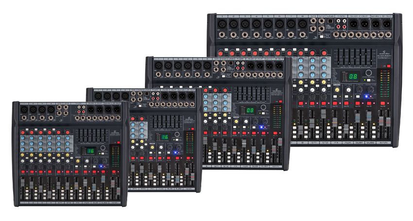
2. OVERVIEW
AlcheMix mixer series has been designed to meet the requests of musicians and en-
tertainment operators who need reliable and professional instruments for live shows,
rehearsal rooms, schools, home recording, etc. The architecture of these 2-Bus mixers
includes 2 subgroups, 2 AUX sends (one with Pre/Post-Fader selection; one Pre-Fader
operation). All channels feature 3-band EQ, MUTE, AFL, Group and main assignments.
A 7-band graphic EQ on the main outputs with precision filters, and a 48 kHz / 24-bit
Digital Effect complete the set of tools of these mixers. The Digital Effect features 16
of the most used presets (Hall-Room-Plate reverb, Delay-Echo, and allow to customize
one parameter through the Tap-Tempo button. The line consists of 4 models: AlcheMix
402FX, 402UFX, 602UFX and 802UFX with 4, 6 and 8 noiseless Mic/Line preamps. The
402-602-802UFX also feature a 2-In/2-Out USB Stereo Sound Card for recording/play-
back on PC/Mac at up to 96kHz/24-bit.
2.1. ALCHEMIX 402 FX Main Features
ff 8 Total Channels
ff 4 Mic/Line channels with wide-range gain noiseless preamps, XLR and balanced ¼”
Jack connectors, 75Hz Low-Cut filter, +48V Phantom Power, Signal/Peak Indicator
ff 2 Stereo Line Channels with balanced ¼” Jack inputs, with gain and Peak Indicator
ff 3-Band EQ, Pan/Balance, Mute, PFL, Group 1-2, Main L-R, 60mm Volume Fader
ff 2 AUX sends (1 with Pre/Post selection for internal DFX or AUX1 Out; 1 Pre-Fader for
AUX2 Out) with channel/master level, AFL, and ¼” Jack outputs
ff Effect/AUX Return control with 60mm Fader, Mute, AFL, Group1-2, L-R assignment,
and balanced ¼” Jack inputs
6ENGLISH
ALCHEMIX SERIES User manual
ff Group 1-2 XLR outputs with 60mm Fader, Mute, AFL, Master Left and Right assign-
ment
ff 7-Band Graphic EQ on Master Bus with precision filters
ff 24-bit/48kHz 16-Preset Digital Effect with Footswitch Out, TAP-Tempo Button and
up to 2 Adjustable Parameters for each Preset
ff 2-Track In/Out RCA connections and Level control
ff Headphones ¼” Stereo Jack Out with Level control
ff XLR Main Outputs with 60mm Fader Control and MUTE
ff Stereo 12-Led VU Meter Bar for Main, PFL/AFL monitoring
ff Stereo ¼” Jack Monitor Output
ff Rugged and Lightweight Metal Case
2.2. ALCHEMIX 402 UFX Main Features
ff 8 Total Channels
ff 4 Mic/Line channels with wide-range gain noiseless preamps, XLR and balanced ¼”
Jack connectors, 75Hz Low-Cut filter, +48V Phantom Power, Signal/Peak Indicator
ff 2 Stereo Line Channels with balanced ¼” Jack inputs, with gain and Peak Indicator
ff 3-Band EQ, Pan/Balance, Mute, PFL, Group 1-2, Main L-R, 60mm Volume Fader
ff 2 AUX sends (1 with Pre/Post selection for internal DFX or AUX1 Out; 1 Pre-Fader for
AUX2 Out) with channel/master level, AFL, and ¼” Jack outputs
ff Effect/AUX Return control with 60mm Fader, Mute, AFL, Group1-2, L-R assignment,
and balanced ¼” Jack inputs
ff Group 1-2 XLR outputs with 60mm Fader, Mute, AFL, Master Left and Right assign-
ment
ff 7-Band Graphic EQ on Master Bus with precision filters
ff 24-bit/48kHz 16-Preset Digital Effect with Footswitch Out, TAP-Tempo Button and
up to 2 Adjustable Parameters for each Preset
ff USB Stereo In/Out Sound Card with up to 96kHz/24-bit recording/playback capa-
bility
ff 2-Track In/Out RCA connections and Level control
ff Headphones ¼” Stereo Jack Out with Level control
ff XLR Main Outputs with 60mm Fader Control and MUTE
ff Stereo 12-Led VU Meter Bar for Main, PFL/AFL monitoring
ff Stereo ¼” Jack Monitor Output
ff Rugged and Lightweight Metal Case
7ENGLISH
ALCHEMIX SERIES User manual
2.3. ALCHEMIX 602 UFX Main Features
ff 10 Total Channels
ff 6 Mic/Line channels with wide-range gain noiseless preamps, XLR and balanced ¼”
Jack connectors, 75Hz Low-Cut filter, +48V Phantom Power, Signal/Peak Indicator
ff 2 Stereo Line Channels with balanced ¼” Jack inputs, with gain and Peak Indicator
ff 3-Band EQ, Pan/Balance, Mute, PFL, Group 1-2, Main L-R, 60mm Volume Fader
ff 2 AUX sends (1 with Pre/Post selection for internal DFX or AUX1 Out; 1 Pre-Fader for
AUX2 Out) with channel/master level, AFL, and ¼” Jack outputs
ff Effect/AUX Return control with 60mm Fader, Mute, AFL, Group1-2, L-R assignment,
and balanced ¼” Jack inputs
ff Group 1-2 XLR outputs with 60mm Fader, Mute, AFL, Master Left and Right assign-
ment
ff 7-Band Graphic EQ on Master Bus with precision filters
ff 24-bit/48kHz 16-Preset Digital Effect with Footswitch Out, TAP-Tempo Button and
up to 2 Adjustable Parameters for each Preset
ff USB Stereo In/Out Sound Card with up to 96kHz/24-bit recording/playback capa-
bility
ff 2-Track In/Out RCA connections and Level control
ff Headphones ¼” Stereo Jack Out with Level control
ff XLR Main Outputs with 60mm Fader Control and MUTE
ff Stereo 12-Led VU Meter Bar for Main, PFL/AFL monitoring
ff Stereo ¼” Jack Monitor Output
ff Rugged and Lightweight Metal Case
2.4. ALCHEMIX 802 UFX Main Features
ff 12 Total Channels
ff 8 Mic/Line channels with wide-range gain noiseless preamps, XLR and balanced ¼”
Jack connectors, 75Hz Low-Cut filter, +48V Phantom Power, Signal/Peak Indicator
ff 2 Stereo Line Channels with balanced ¼” Jack inputs, with gain and Peak Indicator
ff 3-Band EQ, Pan/Balance, Mute, PFL, Group 1-2, Main L-R, 60mm Volume Fader
ff 2 AUX sends (1 with Pre/Post selection for internal DFX or AUX1 Out; 1 Pre-Fader for
AUX2 Out) with channel/master level, AFL, and ¼” Jack outputs
ff Effect/AUX Return control with 60mm Fader, Mute, AFL, Group1-2, L-R assignment,
and balanced ¼” Jack inputs
ff Group 1-2 XLR outputs with 60mm Fader, Mute, AFL, Master Left and Right assign-
ment
8ENGLISH
ALCHEMIX SERIES User manual
ff 7-Band Graphic EQ on Master Bus with precision filters
ff 24-bit/48kHz 16-Preset Digital Effect with Footswitch Out, TAP-Tempo Button and
up to 2 Adjustable Parameters for each Preset
ff USB Stereo In/Out Sound Card with up to 96kHz/24-bit recording/playback capa-
bility
ff 2-Track In/Out RCA connections and Level control
ff Headphones ¼” Stereo Jack Out with Level control
ff XLR Main Outputs with 60mm Fader Control and MUTE
ff Stereo 12-Led VU Meter Bar for Main, PFL/AFL monitoring
ff Stereo ¼” Jack Monitor Output
ff Rugged and Lightweight Metal Case
3. MAINS CONNECTION
Connect the device to mains with the supplied power cable. The wire correspondence is
as follow:
Cable Pin International
Brown Live L
Blue Neutral N
Yellow/Green Earth
WARNING: Earth wire must always be connected! Pay attention to safety!
Before taking into operation for the first time, the installation has to be ap-
proved by an expert.
9ENGLISH
ALCHEMIX SERIES User manual
4. AUDIO CONNECTIONS
You will need several audio cables for the various connections of the mixer. See the fol-
lowing pictures that show the internal wiring of these cables. Be sure to use only high
quality cables.
4.1. RCA Connections
Use RCA cables to connect unbalanced stereo sources with RCA output connectors to
RCA TAPE IN stereo inputs of the mixer (CD Player, MP3 Player, Etc.), or to connect the
mixer RCA TAPE OUT stereo outputs to RCA stereo inputs of an external device (Audio
Recorder, etc.).
Body
Ground / Shield Center
Signal
TAPE
EXTERNAL RECORDER L
( CD-R, DAT, ETC.)
MP3 Player
R
CD Player
4.2. TS JACK Connections
Use mono 1/4” (6.3mm) TS jack to connect unbalanced stereo sources of external
devices, such as musical instruments, etc.
Unbalanced use of 1/4” jack TS connector
Strain relief
clamp Tip
Sleeve
Ground shield Signal
Sleeve
Tip
10ENGLISH
ALCHEMIX SERIES User manual
ST1 ST2
L/mono L/mono
Drum Machine RIGHT RIGHT Electronic Keyboard
1/4“ (6.3mm) mono jack connectors can be used in all ALCHEMIX mixers for LINE IN
inputs.
1
MIC
BAL
OR
LINE UNBAL
1/4“ (6.3mm) mono jack connectors can be used in all ALCHEMIX mixers for Head-
phones output.
PHONES
ALCHEMIX mixers have other 1/4“ (6.3mm) mono jack connectors, such as L/R MONI-
TOR OUT outputs to connect speakers, amplifiers, etc.
Active Amplifier
Speakers
L R
MONITOR OUT
Passive
Speakers
11ENGLISH
ALCHEMIX SERIES User manual
In the ALCHEMIX series mixers, there are other connections that require the use of
mono 1/4 “jack connectors that will be explained later. The connections are as follows:
L/M R
AUX RETURN FX SENDS AUX FW MUTE
4.3. XLR Connections
MIC Inputs accept balanced XLR connectors. Pin-out is as follows:
1
2
3
2.Hot(+) 3.Cold (-) 1.Ground/Shield
MAIN OUT L/R OUT and SUB 1-2 OUT outputs have female XLR plugs. They are used to
connect to active speakers, amplifiers or PA systems.
SUB1-2 OUT MAIN L/R OUT
1 2 L R
12ENGLISH
ALCHEMIX SERIES User manual
5. REAR PANEL
Power
On
1 2
off
150-240V~50/60Hz 15W GND
FUSE: T1A H 250V
1)^IEC Socket with Fuse holder
Plug the power cord into an AC socket properly configured for your particular model. In
case of fuse burn, to prevent the risk of fire and damaging the unit, please use only of
the recommended fuse type as indicated in the rear panel silkscreening. Before replac-
ing the fuse, make sure the unit turned off and disconnected from the AC outlet
2)^POWER Switch
Press power switch to ON position to turn the system on, and to OFF position to turn it
off. When the MIxer is turned on, the blue [POWER] LED on the front panel lights up.
13ENGLISH
ALCHEMIX SERIES User manual
6. MONO MIC/LINE INPUTS AND CONTROLS
This is a female XLR connector that accepts a
(1) balanced microphone input from any type of
microphone, and other balanced audiol sources.
These 1/4” jacks share circuitry (but not phantom
(2) power) with the mic preamps, and can be driven
1
by balanced or unbalanced sources
The LOW CUT (high pass filter) switch cuts the
1 (3)
low frequencies below 75Hz. It is recommended
MIC to use the LOW CUT on all microphone applica-
tions for the voice.
2
GAIN knobs adjust the input sensitivity of the Mic
BAL
OR
LINE UNBAL
(4) preamp (-20dB ÷ +20dB) and Line preamp (0dB
3 LOW CUT
÷ +40dB) inputs.
0
4
20
These controls adjust the amount of high fre-
75Hz
(5)
quencies for each channel (12kHz, +/-15dB).
GAIN
-20 0 +40
+20
0
EQ
5 HIGH
12KHZ
These controls adjust the amount of medium
-15 +15
(6)
0
6 -15 +15
MID
2.5KHZ
frequencies for each channel (2.5kHz, +/- 15dB).
0
7 These controls adjust the amount of low frequen-
LOW
(7)
60HZ
cies for each channel (60Hz, +/-15dB).
-15 +15
8
0 FX
POST
17 These controls adjust the amount of effect for
/PRE
+16
9 (8) each channel to be sent to AUX output or the
0
internal effect processor.
AUX
+16
0
PAN
10
These controls adjust the level of the channel
(9)
L R
11 mute
signal being fed to the Aux bus
dB
10 These controls set the amount of channel signal
sent to the Right and Left output channels,
(10)
5
0
allowing the signal source to be shifted evenly
12
5 SIG
10
16 throughout the stereo image.
15
This button is used to mute the channel signal
15 (11)
20 PFL
30
and it is indicated by the near LED .
13
40 SUB 1-2
50
60
L/R
14
1 (12) This LED Indicates the incoming signal.
These sliders adjust the volume level for each
(13)
channel.
This switch is used to route the channel signal to
(14)
main (Left/Right) output.
14ENGLISH
ALCHEMIX SERIES User manual
This switch is used to route the channel signal to
(15)
SUB 1-2 Output.
When this button is pressed, the signal is sent
from the input channel to the headset and the
corresponding yellow LED lights up. Since this
(16)
signal is pre-fader, it is possible to listen to the
signal with the level totally low before it is ad-
dressed to the MAIN OUT or SUB 1-2 outputs.
This button is used to select the AUX signal as
pre or post fader. When the button is pressed,
(17) the signal is controlled only by the AUX knob. If
the button is not pressed, the signal is controlled
both by the AUX knob and the AUX slider.
15ENGLISH
ALCHEMIX SERIES User manual
7. STEREO INPUTS AND CONTROLS
Stereo channels have two line-level inputs. In
case of mono sources, use LEFT (MONO) input
(1)
only. It will be routed equally on both left and
right channel of MAIN bus.
GAIN knobs adjust line signals input sensitivity
ST1
(2)
(-∞ ÷ +10dB).
1 L/mono
These controls adjust the amount of high fre-
(3)
RIGHT quencies for each channel (12kHz, +/-15dB).
These controls adjust the amount of medium
BAL
(4)
OR
UNBAL
frequencies for each channel (2.5kHz, +/-15dB)
These controls adjust the amount of low frequen-
0
(5)
2 cies for each channel (60Hz, +/-15dB).
-20
GAIN
- +10
These controls adjust the amount of effect for
0
3
EQ
(6) each channel. to be sent to AUX output or the
HIGH
12KHZ
-15 +15
internal effect processor..
0
4 MID
2.5KHZ
These controls adjust the level of the channel
-15 +15
(7)
0
5 signal being fed to the Aux bus
LOW
60HZ
-15 +15
6 These knobs set the amount of channel sig-
0 FX
POST
15 nal sent to the Right and Left output channels,
/PRE
+16
(8)
7 allowing the signal source to be shifted evenly
0
throughout the stereo image.
AUX
+16
0
BAL
8 This button is used to mute the channel signal
(9)
L R
9 and it is indicated by the near LED .
mute
These controls adjust the volume level for each
dB
(10)
channel.
10
14
5
0
This switch is used to route the channel signal to
10 (11)
5 SIG
13 main (Left/Right) output.
10
15
This switch is used to route the channel signal to
12 (12)
20 PFL
SUB 1-2 Output.
30
40 SUB 1-2
50
60
L/R
11 When this button is pressed, the signal is sent
from the input channel to the headset and the
ST1
corresponding yellow LED lights up. Since this
(13)
signal is pre-fader, it is possible to listen to the
signal with the level totally low before it is ad-
dressed to the MAIN OUT or SUB 1-2 outputs.
16ENGLISH
ALCHEMIX SERIES User manual
(14) This LED Indicates the incoming signal.
This button is used to select the AUX signal as
pre or post fader. When the button is pressed,
(15) the signal is controlled only by the AUX knob. If
the button is not pressed, the signal is controlled
both by the AUX knob and the AUX slider.
In all ALCHEMIX series mixers, except for the 402 FX model, the ST2 stereo channel
controls can be dedicated to the USB input on the front panel.
If the “USB PLAYBACK” button is in the ST2 position, all the channel controls will affect
the audio signal coming from USB. If instead the button is in the MAIN position, the
channel controls will have no effect on the audio signal coming from USB.
ST2 USB
L/mono USB
AUDIO
INTERFACE
2 IN/2 OUT
RIGHT
USB PLAYBACK
ST2
MAIN
17ENGLISH
ALCHEMIX SERIES User manual
8. COMMON INPUTS/OUTPUTS
As explained in “4. AUDIO CONNECTIONS” on page 10, ALCHEMIX mixers, in addi-
tion to the MONO MIC/LINE and STEREO input channels, feature other common inputs
and outputs. Below is a brief explanation for each of them.
8.1. TAPE IN/OUT
TAPE IN
Use these unbalanced RCA connectors (L/R) to connect
TAPE
L
the output of a player, such as an analog tape deck, MP3
player, CD/DVD player or a Personal Computer.
TAPE OUT
Use these unbalanced RCA connectors to send out the
R
MAIN MIX signal to a recorder, such as an analog tape
IN OUT deck, hard disk recorder, automatic CD burner or an A/D
converter connected to a Personal Computer.
8.2. AUX RETURN L/R Inputs
Two AUX RETURN inputs are available for outputs of
L/M R
external effects units and are routed to Main L/R or SUB
1-2 buses. If a mono source is used, plugging into the
AUX RETURN
Left jack (L/M) only automatically feeds signal to both
Left and Right.
8.3. SENDS FX/AUX Outputs
FX Send Output
This is an unbalanced output. Normally the FX signal is
sent to the internal effects processor but, when a jack is
inserted into this output connector, the FX signal is sent
to an external effects processor and the internal effects
processor is disconnected.
FX SENDS AUX AUX Send Output
This is an unbalanced output. The audio signal from this
output could be used for a monitor on a stage and also
as input on a external multitrack recorder.
18ENGLISH
ALCHEMIX SERIES User manual
8.4. FW MUTE Input
By connecting a standard switch-type pedal to this input,
internal effects can be activated / deactivated. When the
internal effects are deactivated, “- -” will appear on the
mixer display to indicate that the effects processor has
been deactivated via the footswitch.
FW MUTE
8.5. MONITOR OUT Outputs
L R
These outputs let you hear the mix of incoming audio
signals on external active speakers
MONITOR OUT
8.6. PHONES Output
This output is used to monitor the Main Mix or PFL
(Pre-Fader Listening) on a individual channel using a
standard pair of stereo headphones
PHONES
WARNING: Do not listen with the headphones at high volume for long
periods of time. Doing so may cause hearing loss
8.7. MAIN L/R OUT Outputs
MAIN L/R OUT These are servo balanced outputs (XLR type) that allow
L R the user to connect balanced or unbalanced cables wi-
thout affecting the output level.. The outputs are labeled
“L” and “R” and refer to the main left and right outputs.
These outputs can be connected to the respective inputs
(L / R) of an amplifier, a PA system, etc.
19ENGLISH
ALCHEMIX SERIES User manual
8.8. SUB 1-2 Outputs
SUB1-2 OUT
1 2 These are servo balanced outputs (XLR type) that allow
the user to connect balanced or unbalanced cables
without affecting the output level. These outputs can be
connected to active speakers, amplifiers, PA systems, etc.
9. GENERAL CONTROLS
On the right side of the ALCHEMIX series mixers there are a series of general controls
which will be explained below.
9.1. FX SEND Section
FX Send With this control you can adjust both the effect
(1) level going to the FX SENDS jack and the level
1
0
going to the internal processor.
+6
When this button is pressed, the EFX sends the
2
(2) “Post-Fade” signal to the Monitor / Headphone
output. The corresponding yellow LED lights up
afl
3 This button is used to mute the EFX signal and is
(3)
indicated by the corresponding red LED.
mute
9.2. AUX SEND Section
This control adjusts the signal level going to AUX
(1)
AUX send
SEND jack.
1
0
+6
When this button is pressed, the AUX sends the
2 (2) “Post-Fade” signal to the Monitor / Headphone
afl output. The corresponding yellow LED lights up.
This button is used to mute the AUX signal and is
3 (3)
mute
indicated by the corresponding red LED.
20ENGLISH
ALCHEMIX SERIES User manual
9.3. 2-TRK/CD Section
2-trk/cd
This control adjusts the signal level of the TAPE IN
(1)
input
1
0
+6
When this button is pressed, the AUX sends the
to main
(2) “Post-Fade” signal to the Monitor / Headphone
2 output. The corresponding yellow LED lights up.
9.4. PHONES LEVEL
phones level
0 This knob is used to control the audio signal level of the
headphone as well as monitor out.
+6
9.5. FX Section
dB
10
(1) This fader controls the EFX level..
5
This switch is used to route the
(2)
0
EFX signal to the main (Left/Right)
5
outputs
1 10
This switch is used to route the EFX
(3)
signal to the SUB 1-2 Outputs
4
15
20 AFL
3 When this button is pressed, the
EFX sends the “Post-Fade” signal to
30
40 SUB 1-2
(4) the Monitor / Headphone output.
50
60
2
L/R The corresponding yellow LED
lights up
FX
21ENGLISH
ALCHEMIX SERIES User manual
9.6. AUX Section
This fader is used to set the level
dB (1) of AUX RETURN incoming signal to
10
MAIN or SUB 1-2 outputs.
5
0 This button is used to route the
audio signal from the AUX RETURN
(2)
5
input to the main output. (MAIN
1 10 OUT L/R)
This button is used to route the
4
15
(3) audio signal from the AUX RETURN
20 AFL
input to the SUB 1-2 outputs
30 3 When this button is pressed, the
40
audio signal from the AUX RETURN
SUB 1-2
50
60
2 input is sent (Post-Fade) to the
(4)
Monitor / Headphone output. The
L/R
AUX corresponding yellow LED lights
up.
9.7. SUB 1-2 Section
These faders control the level of the audio
(1)
signal for the SUB 1-2 outputs.
2 This button is used to mute the audio
mute
signal present on the SUB1 or SUB2
(2)
dB outputs. When the button is pressed, the
10
corresponding red LED lights up.
5
0 When this button is pressed, the audio
signal present on the SUB1 or SUB2 sent
5
(3) (Post-Fade) to the Monitor / Headphone
10 output. The corresponding yellow LED
lights up.
15
3
20 AFL When this button is pressed, the audio
4 (4) signal on SUB1 or SUB2 is sent to the
1 MAIN OUT L output (left)
30
40 LEFT
50
5
60
RIGHT When this button is pressed, the audio
(5) signal on SUB1 or SUB2 is sent to the
sub1 MAIN OUT R output (right)
22ENGLISH
ALCHEMIX SERIES User manual
9.8. MAIN Section
3 This fader controls the level of the audio
mute
L R
(1) signal present on the MAIN OUT L (Left)
dB dB output.
10 10
2
5 5
1 0 0
5 5
This fader controls the level of the audio
(2) signal present on the MAIN OUT R (Right)
10 10
15 15 output.
20 20
This button is used to mute the audio
30 30
40 40
50 50
60 60
signal present on the MAIN OUT L / R
(3)
outputs. When the button is pressed, the
main corresponding red LED lights up.
9.9. VU Meter
Clip
The VU Meter is made up of two columns of twelve LEDs
+10
with three colors to indicate different ranges of signal
+7
level
+4 ff GREEN: shows the normal operative level of the
+2 signal (from -30 dBu to 0 dBu)
0
ff YELLOW: shows a high operative level of the signal
-2
(from +2 dBu to +10 dBu)
ff RED: shows a too high signal level (CLIP Level)
-4
Some flashes of the CLIP LEDs may be normal, but if
-7
they remain on for a long time, the gain and volume of
-10
the individual channels must be adjusted so that the VU
-20
Meter does not go to the red zone.
-30
9.10. Common LEDs
This blue LED lights up when power is being sup-
(1)
power plied to mixer
1 2
pfl/afl
This red LED lights up when at least one PFL / AFL
(2)
button is pressed on the mixer
23ENGLISH
ALCHEMIX SERIES User manual
10. PHANTOM POWER
The ALCHEMIX series mixers are able to power condens-
er microphones that require a voltage up to + 48VDC
(PHANTOM POWER). By pressing the [+ 48V] button, all
+48v
mono channels with an XLR connector will be powered.
The lighting of the relative red LED certifies its activation.
If you do not use microphones that require this power
supply, the button must not be pressed (the relative LED
is off)
WARNING: Do not turn on the PHANTOM POWER before connecting a mi-
crophone. Make sure that the output levels are lowered.
11. 7 BAND STEREO GRAPHIC EQUALIZER
The equalizer has seven sliders which gives you up to 12 dB boost or cut at 63 Hz, 160
Hz, 400 Hz, 1 KHz, 2.5 KHz, 6,3 KHz and 16 KHz..
+12 +12
+6 +6
0 0
-6 -6
-12 -12
63 160 400 1K 2.5K 6.3K 16K
7-Band stereo graphic equalizer
12. DIGITAL MULTI EFFECT PROCESSOR
All MIOMIX series mixers, are equipped with a 24-bit / 48kHz digital multi-effect with
16 preset effects (Reverberi Hall / Room / Plate, Delay, Eco, Chorus, etc.). Below is the
list of effects:
1 HALL 5 REVERSE 9 ECHO 13 DETUNE
2 ROOM 6 EARLY REFL. 10 CHORUS 14 PITCH SHIFTER
3 PLATE 7 AMBIENCE 11 FLANGER 15 DELAY + REVERB
4 GATED 8 DELAY 12 PHASER 16 CHORUS + REVERB
The effects section of each model includes some controls:
24ENGLISH
ALCHEMIX SERIES User manual
12.1. 2 x 7 Segments Display and Effect VU Meter
The display ( 2x 7 Segments) indicates
the number of the currently selected
(1)
LEVEL
effect and the parameter values related
CLIP
-3
2 -6
-10
1 to the effect during the setting.
-15
The LED VU Meter gives an indication of
(2)
-20
24-bit DSP Multi-FX Processor
the intensity of the effect.
12.2. Effects Selection
To select one of the 16 preset effects, use the following knob:
Effect Selection
By turning the knob to the right or left you can choose the desired effect. The display
will show the selected effect number flashing. To confirm the number and activate the
new effect, press the knob. If confirmation is not made within 5 seconds, the display will
return to showing the number of the current effect.
12.3. TAP TEMPO Button
TAP
TEMPO
Using this button, it is possible to adjust the settings of some parameters related to
each effect. When the [TAP TEMPO] button is pressed, the display shows the current
value of the effect parameter and the two decimal points on the display flash. When
setting relative TEMPO parameters, press the [TAP TEMPO] button 2 or more times to
determine the time interval that will be shown on the display. The [TAP TEMPO] LED will
flash according to the selected time interval. The adjustment made on each parameter
will be activated immediately. If no further adjustment is made within 5 seconds, the
display will return to showing the number of the current effect. The table below con-
tains all the effects with their parameters:
25ENGLISH
ALCHEMIX SERIES User manual
12.4. Effects and Parameters Table
Min. Max.
N. EFFECT PROG. TAP Min Val Max Val TAP LED
Value Value
01 10
ON/OFF
1 HALL Rev. Time (approx. (approx. Brilliance OFF ON
lighting
1.0 sec) 8.0 sec)
01 10
ON/OFF
2 ROOM Rev. Time (approx. (approx. Brilliance OFF ON
lighting
0.5 sec) 4.0 sec)
01 10
ON/OFF
3 PLATE Rev. Time (approx. (approx. Brilliance OFF ON
lighting
0.5 sec) 5.0 sec)
01 10
ON/OFF
4 GATED Rev. Time (approx. (approx. Brilliance OFF ON
lighting
0.1 sec) 1.0 sec)
01 10
ON/OFF
5 REVERSE Rev. Time (approx. (approx. Brilliance OFF ON
lighting
0.1 sec) 1.0 sec)
10
EARLY 01 ON/OFF
6 REFLECT.
Room Size
(Small)
(Extra Brilliance OFF ON
lighting
Large)
10
01 ON/OFF
7 AMBIENCE Area Size
(Small)
(Extra Brilliance OFF ON
lighting
Large)
01 20 Time
No. of 07 60 Blinks
8 DELAY
repetitions
(min. (max. Interval
(72 BPM) (600 BPM) BPM Tempo
feedback) feedback) (BPM)
No. of 01 40 Time
07 60 Blinks
9 ECHO repetitions (min. (max. Interval
(72 BPM) (600 BPM) BPM Tempo
feedback) feedback) (BPM)
lntensity Tempo 02 48 Blinks
10 CHORUS
(Depth)
01 (1%) 99 (99%)
(LFO-Speed) (24 BPM) (480 BPM MOD Speed
lntensity Tempo 02 48 Blinks
11 FLANGER
(Depth)
01 (1%) 99 (99%)
(LFO-Speed) (24 BPM) (480 BPM MOD Speed
lntensity Tempo 02 48 Blinks
12 PHASER
(Depth)
01 (1%) 99 (99%)
(LFO-Speed) (24 BPM) (480 BPM MOD Speed
Detune 05 50
2nd Voice ON/OFF
13 DETUNE Spreading 01 (1%) 99 (99%)
Delay
(short (long
lighting
5 ms) 50 ms)
Semitones -12 +12
PITCH ON/OFF
14 SHIFT
Step (1 octave (1 octave Detune OFF (0%) ON (25%)
lighting
down) up)
DELAY -9 +9
DLY Time 11 60 Blinks
15 + Ratio (90% Dly; (10% Dly;
(BPM) (116 BPM) (600 BPM) BPM Tempo
REV 10%Rev) 90%Rev)
CHORUS -9 +9 12 24
Reverb ON/OFF
16 + Ratio (90% Ch; (10% Ch;
Time
(short (long
lighting
REV 10%Rev) 90%Rev) 1.2 s) 2.4 s)
26ENGLISH
ALCHEMIX SERIES User manual
13. USB CONNECTION
All the mixers of the ALCHEMIX series, with the exception of the 402 FX model, are
equipped with a 24 bit / 96kHz USB Stereo Input / Output sound card which allows you
to connect to a computer and record or play high quality audio files. The USB connec-
tion on the front panel of the mixer
When connecting the computer to the USB 2.0 connector, make sure to observe the
following points. Failing to do so risks freezing the computer and corrupting or losing
the data. If the computer or the mixer freezes, restart the application software or the
computer OS, or don’t connect the mixer and then on again.
ff Use an AB type USB cable. USB 3.0 cable cannot be used.
ff Before connecting the computer to the USB 2.0 terminal, exit from any power-saving
mode of the computer (such as suspend, sleep, and standby).There is no need to
install any specialized driving program for this USB2.0 audio port. Just plug in to use.
For the first use, the computer will find a new hardware. Please follow the operations
to complete all installations as instructed by the computer until the recognition of
ending by the computer. Then, the USB2.0 external sound card is ready to use.
ff The USB2.0 external sound card is named as “USB Audio CODEC”. It can be used
with Windows XP or later and MAC OSX operating systems. After recognition of the
external sound card by the computer, you choose as the current audio input and
output device in the audio device properties. If it cannot be set up automatically, you
are required to enter the computer’s audio device properties, and then choose the
“USB Audio CODEC” in the list of input and output audio devices.
ff To ensure better sound effects, we recommend setting the input and output volume
to the maximum in the computer’s audio properties.
27ENGLISH
ALCHEMIX SERIES User manual
14. SPECIFICATIONS
ALCHEMIX Model 402 FX 402 UFX 602 UFX 802 UFX
4 Mic/Line + 4 Mic/Line + 6 Mic/Line + 8 Mic/Line +
Configuration Channels
2 Stereo 2 Stereo 2 Stereo 2 Stereo
Nominal Gain (Mic/ 60 dB, 40 dB, 20 dB
Line/Stereo Line)
Max Gain (Mic/Line/ 80 dB, 60 dB, 40 dB
Stereo Line)
Input Sensitivity
Mic (Gain Min/Gain -20 dBu/+20 dBu
Max)
Line (Gain Min/Gain 0 dBu/+40 dBu
Max)
Stereo Line (Gain Min/
Gain Max) -∞ dBu /+10 dBu
Aux Return 0 dBu
Tape In -2 dBu
Max Input Levels
MIc +24 dB
Line +24 dB
Stereo Line +20 dB
Aux +20 dB
Tape +20 dB
Input Impedance
Mic Input 2Kohm Balanced
Line Input 20Kohm (Balanced)/10Kohm (Unbalanced)
Aux Return Input 20Kohm Balanced
Tape Record Inputs 10Kohm Balanced
Output Levels
Main/Group 0dBu (0.775V RMS) Nominal/ +22dBu (10V RMS) Max
Monitor 0dBu (0.775V RMS) Nominal/ +22dBu (10V RMS) Max
Record Out -2dB (600mv RMS)/ +22dBu (10V RMS) Max
Aux Send 0dBu (775mv RMS)/ +22dBu (10V RMS) Max
Output Impedance
Main/Group 75ohm
Monitor 75ohm
Record Out 1Kohm
Aux Send 75ohm
Phones 33ohm min
Frequency Response 20Hz to 20KHz (+0/-2dB)
Total Harmonic Distor-ENGLISH
ALCHEMIX SERIES User manual
Noise
ERN Mic Input < -122dB
(150ohm)
Ratio < -85dB
Equalization
Mono MIC (Treble/Mid/ ±15dB (12KHz HF / 2.5 KHz MF/60Hz LF)
Bass)
Stereo Line (Treble/Mid/ ±15dB (12KHz HF / 2.5 KHz MF/80Hz LF)
Bass)
General Information
16 Effects, 24-bit Sigma-Delta, 256-times oversampling, 48kHz
Effect
sampling rate
Up to 24-bit/96kHz Stereo Input/Output Stream-
USB I/O Soundcard NO
ing, USB Class-2.0 compliant
Phantom supply +48V
Power Supply 150V-240V~50Hz, 15W Max
376 x 316.5 x 430 x 316.5 x
Size (WxDxH) 322 x 316.5 x 134 mm
134 mm 134 mm
455 x 165 x 392 455 x 165 x 392
Carton Size (WxDxH) 405 x 165 x 392 mm mm mm
Net Weight 4.5 kg 5.0 kg 5.5 kg
Gross Weight 5.5 kg 6.0 kg 6.5 kg
Our products are subject to change. Modifications to technical features remain subject to change without notice
29ENGLISH
ALCHEMIX SERIES User manual
15. WARRANTY AND SERVICE
All SOUNDSATION products feature a limited two-year warranty. This two-year warranty is specific
to the date of purchase as shown on your purchase receipt.
The following cases/components are not covered from the above warranty:
• Any accessories supplied with the product
• Improper use
• Fault due to wear and tear
• Any modification of the product effected by the user or a third party
SOUNDSATION shall satisfy the warranty obligations by remedying any material or manufacturing
faults free of charge at SOUNDSATION’s discretion either by repair or by exchanging individual
parts or the entire appliance. Any defective parts removed from a product during the course of a
warranty claim shall become the property of SOUNDSATION.
While under warranty period, defective products may be returned to your local SOUNDSATION
dealer together with original proof of purchase. To avoid any damages in transit, please use the
original packaging if available. Alternatively you can send the product to SOUNDSATION SERVICE
CENTER – Via Enzo Ferrari , 10 – 62017 Porto Recanati - Italy . In order to send a product to service
center you need an RMA number. Shipping charges have to be covered by the owner of the prod-
uct.
For further information please visit www.soundsationmusic.com
16. WARNING
PLEASE READ CAREFULLY – EU and EEA (Norway, Iceland and Liechtenstein) only
This symbol indicates that this product is not to be disposed of with your household waste, ac-
cording to the WEEE Directive (2202/96/EC) and your national law.
This product should be handed over to a designated collection point, e.g., on an authorized one-
for-one basis when you buy a new similar product or to an authorized collection site for recycling
waste electrical and electronic equipment (WEEE).
Improper handling of this type of waste could have a possible negative impact on the environment
and human health due to potentially hazardous substances that are generally associated with EEE.
At the same time, your cooperation in the correct disposal of this product will contribute to the
effective usage of natural resources.
For more information about where you can drop off your waste equipment for recycling, please
contact your local city office, waste authority, approved WEEE scheme or your household waste
disposal service.
30ITALIANO
SOMMARIO
1. DISIMBALLAGGIO..................................................................................................................... 34
2. DESCRIZIONE ........................................................................................................................... 34
2.1. Caratteristiche Principali ALCHEMIX 402 FX...............................................................................................34
2.2. Caratteristiche Principali ALCHEMIX 402 UFX............................................................................................35
2.3. Caratteristiche Principali ALCHEMIX 602 UFX............................................................................................36
2.4. Caratteristiche Principali ALCHEMIX 802 UFX............................................................................................36
3. CONNESSIONE ALLA RETE ELETTRICA................................................................................... 37
4. CONNESSIONI AUDIO............................................................................................................. 38
4.1. Connessioni RCA...................................................................................................................................................38
4.2. Connessioni JACK..................................................................................................................................................38
4.3. Connessioni XLR....................................................................................................................................................40
5. PANNELLO POSTERIORE.......................................................................................................... 41
6. INGRESSI MONO MIC/LINE E CONTROLLI............................................................................. 42
7. INGRESSI STEREO E CONTROLLI............................................................................................. 44
8. INGRESSI/USCITE COMUNI..................................................................................................... 46
8.1. TAPE IN/OUT...........................................................................................................................................................46
8.2. Ingressi AUX RETURN L/R..................................................................................................................................46
8.3. Uscite SENDS FX/AUX.......................................................................................................................................46
8.4. Ingresso FW MUTE...............................................................................................................................................47
8.5. Uscite MONITOR OUT.........................................................................................................................................47
8.6. Uscita PHONES (Cuffie)......................................................................................................................................47
8.7. Uscite MAIN L/R OUT..........................................................................................................................................47
8.8. Uscite SUB 1-2.......................................................................................................................................................48
9. CONTROLLI GENERALI............................................................................................................. 48
9.1. Sezione FX SEND...................................................................................................................................................48
9.2. Sezione AUX SEND...............................................................................................................................................48
9.3. Sezione 2-TRK/CD................................................................................................................................................49
9.4. Livello del volume delle Cuffie........................................................................................................................49
9.5. Sezione FX...............................................................................................................................................................49
9.6. Sezione AUX............................................................................................................................................................50
9.7. Sezione SUB 1-2....................................................................................................................................................50
9.8. Sezione MAIN.........................................................................................................................................................51
9.9. VU Meter..................................................................................................................................................................51
9.10. LEDs Comuni...........................................................................................................................................................51
10. ALIMEMTAZIONE PHANTOM.................................................................................................. 52
11. EQUALIZZATORE GRAFICO A 7 BANDE STEREO................................................................... 52
12. PROCESSORE DIGITALE MULTI EFFETTO............................................................................... 52
12.1. Display 2 x 7 Segmenti e VU METER effetto..............................................................................................53
12.2. Selezione Effetti.....................................................................................................................................................53
12.3. Pulsante TAP TEMPO...........................................................................................................................................53
12.4. Tabella Effetti e Parametri..................................................................................................................................54
13. CONNESSIONE USB.................................................................................................................. 55
14. SPECIFICHE................................................................................................................................ 56
15. GARANZIA E ASSISTENZA....................................................................................................... 58
16. AVVISO....................................................................................................................................... 58
31ITALIANO
IMPORTANTI SIMBOLI DI SICUREZZA
Il simbolo è usato per indicare che in questa apparecchiatura sono
presenti alcuni terminali sotto tensione pericolosi, anche in condizioni
di normale funzionamento, che possono costituire rischio di scosse
elettriche o di morte
Il simbolo viene utilizzato nella documentazione di servizio per indi-
care che uno specifico componente può essere sostituito esclusiva-
mente dal componente specificato nella documentazione per motivi di
sicurezza.
Terminale di Terra
Corrente/Tensione alternata
Terminale in tensione pericoloso
Indica che l’apparato è acceso
Indica che l’apparato è spento
Precauzioni da osservare per evitare il pericolo di ferimento o di morte
WARNING: per l’utilizzatore.
CAUTION: Precauzioni da osservare per evitare danni all’apparecchio.
CURA DEL PRODOTTO
ff Leggete queste istruzioni
ff Conservate queste istruzioni
ff Rispettate tutte le avvertenze
ff Seguite tutte le istruzioni
1) ACQUA / UMIDITA
L’apparecchio deve essere protetto dall’umidità e dalla pioggia, non può essere usato
in prossimità di acqua; ad esempio nei pressi di una vasca da bagno, di un lavandino, di
una piscina, etc.
2) Calore
L’apparecchio deve essere posto lontano da fonti di calore come radiatori, stufe o altri
apparecchi che producono calore.
32ITALIANO
MANUALE D’USO MIXER SERIE ALCHEMIX
3) VENTILAZIONE
Non ostruite le prese d’aria per la ventilazione: ciò potrebbe provocare incendi. Installa-
te sempre l’unità secondo le istruzioni del produttore.
4) Introduzione di oggetti e liquidi
Non introdurre oggetti o versare liquidi all’interno dell’apparato per ragioni di sicurezza
5) Cavo di alimentazione e spina
Evitate che il cavo di alimentazione venga calpestato o schiacciato, in particolare in
prossimità delle spine, delle prese e del punto in cui fuoriesce dall’apparecchio. Non
vanificate la finalità di sicurezza della spina con messa a terra. Una spina normale o
“polarizzata” ha due soli terminali; una spina con messa a terra ha un terzo polo di
terra. Questo ulteriore terminale serve per la vostra sicurezza. Se la spina fornita non si
inserisce nella presa, consultate un elettricista per l’eventuale sostituzione.
6) ALIMENTAZIONE
L’apparecchio deve essere collegato alla sorgente di alimentazione elettrica del tipo
indicato sull’apparecchio o descritto nel manuale. In caso contrario si potrebbero
provocare danni al prodotto ed eventualmente all’utente. Staccate la spina in caso di
temporali o quando non viene utilizzato per lunghi periodi di tempo.
7) FUSIBILE
Per evitare il rischio di incendi e di danni all’unità, utilizzate solo il tipo di fusibile
descritto nel manuale. Prima di sostituire il fusibile, assicuratevi che l’apparecchio sia
spento e scollegato dalla presa di corrente.
8) Collegamento alla rete elettrica
Il collegamento elettrico improprio può invalidare la garanzia del prodotto.
9) RUMORE ED INTERFERENCE
Non utilizzare il dispositivo in prossimità di TV, radio, apparecchiature stereo, telefoni
cellulari o altri dispositivi elettrici. In caso contrario, il dispositivo, la TV o la radio po-
trebbero generare rumore ed interference.
10) Pulizia
Pulite solo con un panno asciutto. Non utilizzate solventi come benzolo o alcol.
11) Manutenzione
Non effettuate qualsiasi altro intervento al di fuori di quelli descritti nel manuale. Per
eventuale assistenza rivolgetevi solo a personale qualificato. Utilizzate solo accessori /
componenti suggeriti dal produttore.
33You can also read


