Analysis of the Influence of DTM Source Data on the LS Factors of the Soil Water Erosion Model Values with the Use of GIS Technology
←
→
Page content transcription
If your browser does not render page correctly, please read the page content below
remote sensing
Article
Analysis of the Influence of DTM Source Data on the LS Factors
of the Soil Water Erosion Model Values with the Use of
GIS Technology
Anna Fijałkowska

                                          Department of Photogrammetry, Remote Sensing and Spatial Information Systems, Warsaw University of
                                          Technology, Pl. Politechniki, 100-661 Warsaw, Poland; anna.fijalkowska@pw.edu.pl

                                          Abstract: Counteracting soil degradation is one of the strategic priorities for sustainable development.
                                          One of the most important current challenges is effective management of available resources. Multiple
                                          studies in various aspects of soil water erosion are conducted in many research institutions in the
                                          world. They concern, among others, the development of risk estimation models and the use of
                                          new data for modelling. The aim of the presented research was a discussion on the impact of the
                                          accuracy and detail of elevation data sources on the results of soil water erosion topographic factors
                                          modelling. Elevation data for this research were chosen to reflect various technologies of data
                                          acquisition, differences in the accuracy and detail of field forms mapping and, consequently, the
                                          spatial resolution of the digital terrain models (DTMs). The methodology of the universal soil loss
                                          equation USLE/RUSLE was used for the L and S factors modelling and calculation. The research
                                          was carried out in three study areas located in different types of geographical regions in Poland:
                                uplands, highlands and lake districts. The proposed methodology consisted of conducting detailed
                                   comparative elevation and slope value assessments, calculating the values of topographical factors
Citation: Fijałkowska, A. Analysis of     of the universal soil loss equation: slope length (L) and slope (S) and a detailed analysis of the
the Influence of DTM Source Data on       total LS factors values. An approach to assess LS factors values within homogeneous areas such
the LS Factors of the Soil Water          as agricultural plots has also been proposed. The studies draw the conclusion that the values of
Erosion Model Values with the Use of      topographical factors obtained from various DTM sources were significantly different. It was shown
GIS Technology. Remote Sens. 2021,        that the choice of the right modelling data has a significant impact on the L and S factors values and,
13, 678. https://doi.org/10.3390/
                                          thus, also, on the decision-making process. The conducted research has definitely shown that data of
rs13040678
                                          the highest accuracy and detail should be used to study local phenomena (inter alia erosion), even
                                          analysing a large area.
Academic Editor: Dimitrios Alexakis

Received: 31 December 2020
                                          Keywords: soil water erosion; USLE; RUSLE; L-factor; S-factor; digital terrain model; DTM spatial
Accepted: 9 February 2021                 analysis; spatial modelling; Janowice; Winiarki; Bolcie
Published: 13 February 2021

Publisher’s Note: MDPI stays neutral
with regard to jurisdictional claims in   1. Introduction
published maps and institutional affil-        Soils are the basis for plant production and food security. The 2015 Food and Agri-
iations.                                  culture Organization (FAO) report “Status of the World’s Soil Resources” began with the
                                          statement: “Soils are fundamental to life on Earth” [1]. In paragraph 10, The Updated
                                          FAO World Soil Charter of 2015 emphasised that soil degradation significantly reduces or
                                          even eliminates the natural functions of soil. Preventing or minimising soil degradation
Copyright: © 2021 by the author.          is necessary to maintain basic functions of soils and is much more economically viable
Licensee MDPI, Basel, Switzerland.        than the reclamation of degraded soils [2,3]. Unfortunately, it is estimated that most of
This article is an open access article    the world’s soil resources are in merely adequate, poor or very poor conditions, and 33%
distributed under the terms and           of the land is moderately-to-severely degraded due to, among others, water, wind and
conditions of the Creative Commons        crop erosion. It is predicted that a further loss of soil productivity threatens the balance
Attribution (CC BY) license (https://     and security of food production, which will cause further price increases and potentially
creativecommons.org/licenses/by/          worsen the quality of life of millions of people [2].
4.0/).

Remote Sens. 2021, 13, 678. https://doi.org/10.3390/rs13040678                                     https://www.mdpi.com/journal/remotesensing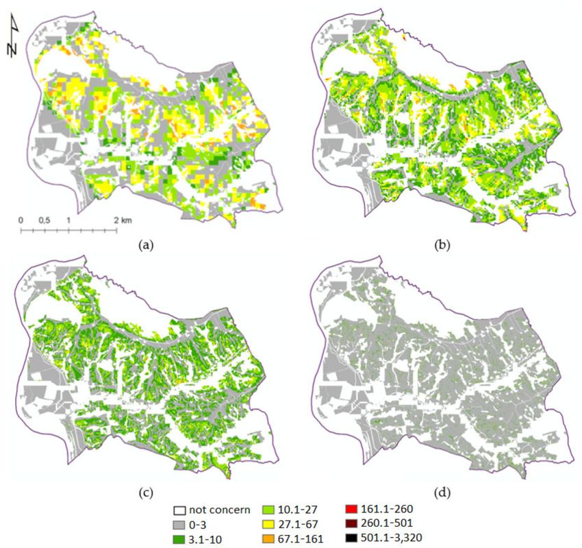
Remote Sens. 2021, 13, 678                                                                                            2 of 37

                                  In 1983, Renard and Foster, working on a mathematical description of the factors
                             causing water erosion, proposed a general formula showing the dependence of the extent
                             of soil loss on the factors that cause it [4]. Since then, various approaches to erosion mod-
                             elling have been developed (expert-based [5,6], conceptual, empirical [7–9] and physics-
                             based/mechanistic models [7,10]), and these different models have different versions that
                             have undergone many changes and improvements as research has developed [11]. Empiri-
                             cal models constitute an important group of erosion models. These formulas are developed
                             on the basis of the results of research conducted on experimental plots. It is estimated
                             that, for calibrating empirical models of water erosion, we currently have results from
                             over 24,000 measurements conducted mainly in the USA, Europe, Brazil and China [12].
                             Unfortunately, they are often impossible to compare due to the large diversity of climatic
                             zones and the characteristics of individual slopes [7–9,13,14]. Measurements on experi-
                             mental plots of a given size and with an area limited by natural terrain barriers are not
                             able to adequately reflect the dynamics of the erosion process. During each erosion event,
                             the distance of displacement of the eroded soil material may be different [14]. Moreover,
                             this type of research requires significant financial outlays and is time-consuming, and
                             the obtained results often cannot be extrapolated to larger areas [7,9,15,16]. Despite the
                             above-mentioned limitations, the ease of implementation of empirical equations and the
                             availability of data make these models one of the most popular methods used to assess the
                             impact of water erosion.
                                  The most widely used model in the empirical model range is the Universal Soil Loss
                             Equation, developed in 1965 [17] and its modifications presented in many later studies.
                             The formula for calculating the average annual soil loss is presented in Equation (1):

                                                                A= R * K * C * L * S * P                                 (1)

                             where:
                             A = mean annual soil loss (in t ha−1 yr−1 ),
                             R = rainfall erosivity factor (in MJ mm ha−1 h−1 yr−1 ),
                             K = soil erodibility factor (in t h MJ−1 mm−1 ),
                             C = cover management factor (dimensionless),
                             L = slope length factor (dimensionless),
                             S = slope steepness factor (dimensionless) and
                             P = support practice factor (dimensionless).
                                   Models based on the universal soil loss equation USLE/RUSLE methodology [18] are
                             commonly used to estimate the risk of soil water erosion in analyses covering small areas
                             (single farmland and slopes), as well as in analyses for large areas (one or more catchments).
                             Some of the research conducted was undertaken by [19–48]. The European Soil Data Centre
                             (ESDAC) and the European Soil Bureau (JRC) also use these equations when calculating
                             soil loss, including in the PESERA, G2 and RUSLE2015 models [42]. Various authors have
                             emphasised the importance of proper determination of the impact of each factor included
                             in a given erosion model: the precipitation [25,49], the natural susceptibility of soils to
                             erosion [22,50] and land cover and land use [42,50,51], but the vast majority indicate that
                             the factors of length (L) and slope (S) are those whose precise calculations determine the
                             obtained results to the greatest extent. Additionally, uncertainty analyses indicate the
                             significance of these factors [19,22,29,36,37,42,49–57].
                                   The models mentioned above differ, inter alia, in the formulas that are used to calculate
                             the impacts of individual factors. In determining the impact of the topography, the most
                             common calculation of the L factor value is based on the distance travelled by the runoff
                             water or on the basis of the unit upslope contributing area, understood as the area from
                             which the water flows to a given point [19] (considered to better reflect the erosive impact
                             of the track passed by water flowing down the slope than a simple linear flow path).
                             The determination of unit upslope contributing areas involves the identification of flow
                             directions for this purpose and the calculation of flow accumulation on its basis. Algorithms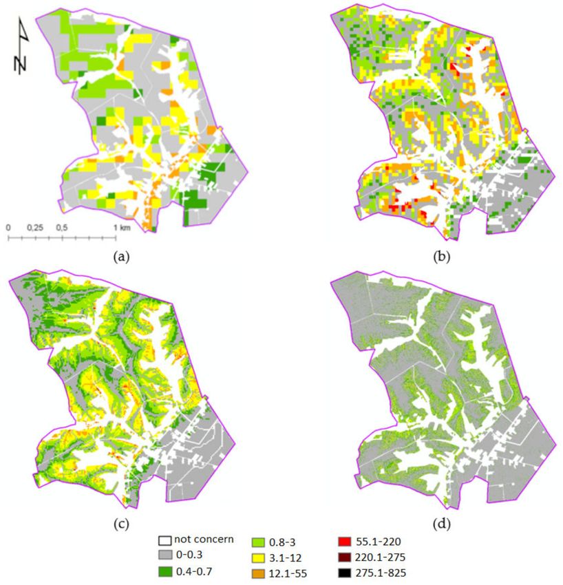
Remote Sens. 2021, 13, 678                                                                                            3 of 37

                             that can be used to determine the paths of water flowing down the slope is the assumption
                             of water runoff from the higher raster cells to only one cell (single flow) or to several lower
                             cells (multiple flow). The most frequently used single-flow algorithms are D8, Rho8 and
                             KRA, while the multiple flow algorithms include, among others, DF8, FRho8, D∞, MD∞
                             and DEMON [37,58]. Despite the expected accuracy of the obtained results, the tests of the
                             above-mentioned algorithms do not always yield similar results, which is often caused by
                             the complexity of the terrain being analysed [59]. Some authors emphasise a much better
                             efficiency of the DEMON algorithm or divergent runoff models [23,37,60], while others
                             indicate no significant differences in the course of the hydrographic network determination
                             and the value of the runoff accumulation [61,62]. The common use of the USLE/RUSLE
                             models facilitates a comparison of the obtained results. A review of the literature sources
                             showed that various data are used to calculate water erosion soil losses and to indicate areas
                             particularly exposed to it (so-called “hot spots”). It can be seen that the obtained results
                             were sometimes significantly different. This is confirmed by the comparison (review) of
                             the selected results of European studies presented in Table 1.
Remote Sens. 2021, 13, 678 4 of 37
Table 1. Review of soil loss results from selected European studies in the period 1996–2020, and a comparison with the results of field studies from USA and Europe investigations.
Equation: U (Universal Soil Loss Equation (USLE)) and R (Revised Universal Soil Loss Equation), flow: flow length (l) and unit contribution area (a) and flow algorithm: single flow
direction (SFD) and multiple flow direction (MFD).
No Max Loss Mean Loss Equation DTM DTM res. Flow Research Research Research Region Country Publication
t/ha/y t/ha/y Source [m] Flow Algorithm Date Localisation Area Date Bibliography
- 20.5 U chart/table - - - 600700 USA field - USA 1978 [17]
- 28.1 R chart/table - - - 800 Indiana field - USA 1991 [63]
- 17 field - 1955–1995 field - Europe 1995 [64]
- 0.84 field - 500 field - Europe 1995 [65]
- 10–20 field - - - - 1950–2010 1056 plots field - Europe 2012 [66]
Topo map Ganspoel
1 - 0.5 U 5 a MFD 900 2.1 km2 Flanders BE 1996 [19]
10k catchment
Topo map SFD Kemmelbeek
2 - 4.1 R 10 l (Rho8) 1993–1995 1075 ha Flanders BE 2000 [67]
10k Watershed
USGS
3 - 11.1 R HYDRO1k 1,000 l - 800 - - - Europe 2003 [68]
4 >20 1 U SRTM 100 l - - - - - Europe 2010 [32]
Central
5 16 1.18 U Swisstopo 25 l - 2006/2007 Urseren Valley 67 km2 CH Alps
CH 2010 [69]
Małopolskie
6 97.8 - R SRTM 90 a - - - 15,183 km2 Voivod- PL 2012 [35]
ship
test field near Roztocze
57 >30 - U - 21 l - 2009
Gorajec 84 km2 region PL 2013 [38]
8 >15 4.3 U - 20 a MFD (D∞) 2004–2008 - 21,115 km2 Hesse DE 2013 [52]
aerial
9 13.8 3.8 U
images
15 a - 1981–2009 - 15,183 km2 Małopolskie PL 2014 [70]
part of
10 - 19 U - - l - - Bystrzyca 8.8 km2 Dolnoślaskie
˛ PL 2012 [71]
Dusznicka
Herdade do region of
11 >200 14.1 R Topo map 14.98 a - - 739 ha PT 2012 [72]
Roncão Alentejo
Alqueva region of
12 >30 15.1 R SRTM 30 a - 2006–2009
reservoir 250 km2 Alentejo
PT 2014 [73]
FÖMI. Farkas Ditch Sopron
13 6.4 0.5 U 5 a 2008–2009 0.6 km2 HU 2012 [74]
DDM-5 catchment Hills
Topo map Turbolo
14 40 5.65 R
10k
- l - 2006
catchment 30 km2 Calabria IT 2016 [75]
Salandrella- Basilicata
15 >40 9.02 R - 25 & 10 a MFD (D∞) 1955–2002
Cavone 74 km2 Region
IT 2008 [76]
Regione Adda river Rhaetian
16 >50 1.8 R
Lombardia
90 & 20 a - -
basin 5170 km2 Alps
IT. CH 2011 [77]
Upper
17 >50 - R - 90 a - - Soča/Isonzo 1300km2 Julian Alps SLO, IT 2011 [77]
basin
Alpine River CH, AT,
18 >100 - R - 90 a - 1985–2005
Inn basin 26,000 km2 - DE, IT 2011 [77]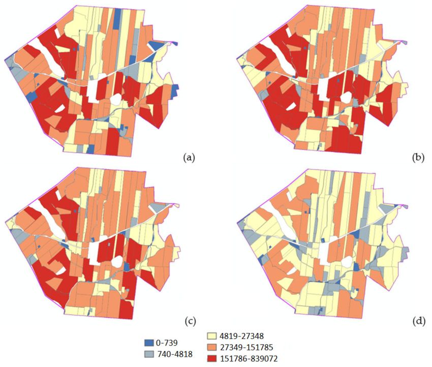
Remote Sens. 2021, 13, 678                                                                                                                                                        5 of 37

                                                                               Table 1. Cont.

  No       Max Loss      Mean Loss   Equation    DTM      DTM res.            Flow       Research      Research       Research     Region       Country   Publication
            t/ha/y        t/ha/y                Source      [m]      Flow   Algorithm      Date       Localisation     Area                                 Date        Bibliography

                                                                                                     Tusciano river               Campania
   19        5458.6          57         R          -        20        l         -          2001          basin        261 km2      Region         IT         2007          [78]
                                                                                                      Arroyo del
   20        204.6            -         R          -        10        a     MFD (D∞)            -                     768.62 ha   Guadalajara     ES         2012          [79]
                                                                                                      Lugar basin
                                                                                                       Tierra de                  province of
   21         45.8           17.4       R          -         3        a         -          2018                        20 ha                      ES         2020          [80]
                                                                                                        Barros                      Badajoz
                                                                                                     Camastra river                Basilicata
   22        11,680          71.4       R          -         5        a       MFD               -        basin        350 km2       Region
                                                                                                                                                  IT         2020          [81]
                                                                                          2002 &      Cephalonia                  Cephalonia
   23         >75            12.8       R          -        20        -         -          2012         Island        773 km2        Island
                                                                                                                                                  GR         2018          [82]
                                                EU-DEM
   24         >50            2.46       R       (STRM +     25        a       MFD          2000s           -              -            -        Europe       2015
                                                 ASTER                       (TFM)                                                                                         [43]
                                                 GDEM)
                                                 ASTER
   25         >50            0.89       R       GDEM /      250       a       MFD        2001–2012         -              -            -        World        2017          [28]
                                                 SRTM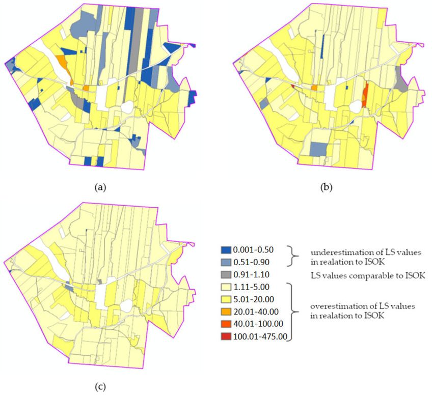
Remote Sens. 2021, 13, 678                                                                                            6 of 37

                                   The analysis of the above list led to the following questions: why are there such
                             differences in the obtained results (maximum soil loss values vary from 6.4 t ha−1 y−1
                             to 11,680 t ha−1 y−1 , while research at the pan-European level reaches little more than
                             50 t ha−1 y−1 )? Where do they come from? What causes such discrepancies? Which factors
                             contribute to such differences? If it is the influence of the length and gradient of the slope,
                             do the obtained differences result from the digital terrain model (DTM) source data, their
                             resolution, the formula used or its implementation in a software used?
                                   The literature review gives the impression that, usually, a widely available data is
                             used without first considering the appropriate accuracy and detail of the source data
                             and their impact on the modelling results. Very often, a medium-scale DTM is used to
                             model a phenomenon that is clearly local in nature. This approach is understandable
                             for analyses performed in the absence of available data of adequate detail and accuracy,
                             but it raises doubts in times of the widespread availability of high-resolution elevation
                             data. Although the term “high-resolution DTM” has significantly changed its meaning
                             since the inception of Geographical Information System (GIS) technology, many authors
                             dealing with soil water erosion indicate that the use of source data with high accuracy
                             and detail is an essential aspect of erosion modelling [34,37,55,83–85]. Moreover, some
                             studies concerning the uncertainty of the model results indicate that the uncertainty of
                             estimating the values of the L and S factors is crucial. This impact can be reduced by
                             using DTM with very high accuracy and detail [11,39,52,85–88]. Initially, the data sources
                             for calculating the values of the L and S factors came from field studies; then, they were
                             obtained by vectorisation of the base of topographic maps in different scales [39] and,
                             then, from DTM from various sources (active and passive satellite data [38,56], aerial
                             photography or laser scanning [85,89,90]). The spatial resolution of DTM varied from
                             0.25 m [91] to 90 m, including data from the SRTM mission [32,35] DTED Level 2 [32,92]
                             EU-DEM model (SRTM update based on ASTER GDEM) [42], as well as models from aerial
                             photos and ALS [85,89,90]. For individual fields, GNSS measurements were also made in
                             a regular grid [60]. In the project implemented for the entire EU area, the values of the L
                             and S factors were calculated from the EU-DEM model (SRTM + ASTER) with a spatial
                             resolution of 25 m, as it is the highest spatial resolution of a homogeneous DTM available
                             for all of Europe. Individual Member States have used DTM with a resolution of 10–40 m
                             to model the risk of water erosion [93].
                                   However, the sensitivity of the erosion models to the source data used has not been
                             comprehensively investigated so far, although the publications emphasise the impact of
                             the accuracy and detail of the source DTM on the values of the L and S factors obtained
                             as a result of its processing [39,43,94]. Tests evaluating the effect of reducing the spatial
                             resolution of source DTM on the modelling results were conducted by, among others,
                             Molnar and Julien [95], Wilson [58], Lee and Lee [88], Liu et al. [96] and Zhao et al. [83].
                                   The methodology used by these researchers assumed the study of the dependence
                             of the obtained results on the spatial resolution of DTM and the subsequent versions of
                             the original DTM, with increasingly lower resolutions (obtained as a result of degradation
                             of the source data resolution). Such models are consistent and only simulate the real data
                             with lower resolutions. However, such comparisons did not make possible the check of
                             the impact of the real data source on the erosion modelling (e.g., possible shifts of terrain
                             forms, lack of visibility of minor terrain forms; this problem is well-reflected in comparative
                             analyses of the hydrographic network system and catchment boundaries obtained from
                             DTM from various sources). Taking into account the high availability of various elevation
                             data for the area of the country or even on a continental scale (obtained with the use of
                             different technologies and characterised by different accuracies and details). There is a need
                             to conduct in-depth research aimed at determining the impact of the source of elevation
                             data on the results of determining the values of the L and S factors of soil water erosion
                             modelling and, consequently, on the determination of areas at risk of water erosion.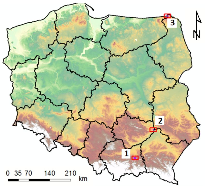
Remote Sens. 2021, 13, 678                                                                                            7 of 37

                             2. Materials and Methods
                             2.1. Study Areas
                                   The proposed methodology was applied in 3 research areas, the selection of which
                             was preceded by an analysis of data available for Poland describing the risk of water
                             erosion developed by The Institute of Soil Science and Plant Cultivation (IUNG). The
                             water erosion risk database distinguishes 6 levels (an expert classification based on: slope
                             class, soil texture classes and total annual rainfall class) of erosion risk: from 0—no risk
                             to 5—very strong erosion risk (dimensionless). The research areas are characterised by
                             varied topography and were selected in such a way that they contain areas of high erosion
                             risk: levels 4 and 5, as well as areas with no risk and low erosion risk: levels 0 and 1. The
                             research areas are located in various types of physical and geographical regions of Poland:
                             foothills, highlands and lake districts (Figure 1).

                             Figure 1. The research areas localisation: 1—Janowice, 2—Winiarki and 3—Bolcie (hypsometric map
                             from WMS: http://mapy.geoportal.gov.pl; (accessed on 21 December 2020); Ref. Syst: EPSG 2180).

                                  The research area of Janowice covers an area of 1355 ha and is located in the Western
                             part of Pogórze Ci˛eżkowickie. The terrain heights (based on ALS data) range from 199 m
                             above sea level up to 454 m above sea level. The maximum slopes of the terrain are
                             significant and reach values up to 78◦ (ALS data) (Figure 2a).The land is mainly covered by
                             grasslands and agricultural crops (55.9%), forests and wooded areas (29.3%), built-up areas
                             (5.8%) and permanent crops (4.5%) (based on the BDOT10k topo reference database).
                                  The research area of Winiarki covers an area of 277 ha and is located in the eastern part
                             of the Sandomierz Upland. Terrain heights (ALS data) range from 138 m above sea level up
                             to 208 m above sea level, and the slope values (ALS data) in this area reach 74◦ (Figure 3a).
                             The land is mainly covered by permanent crops (38.1%), grasslands and agricultural crops
                             (32.5%), forests and wooded areas (23.3%) and built-up areas (5.5%) (based on the BDOT10k
                             topo reference database).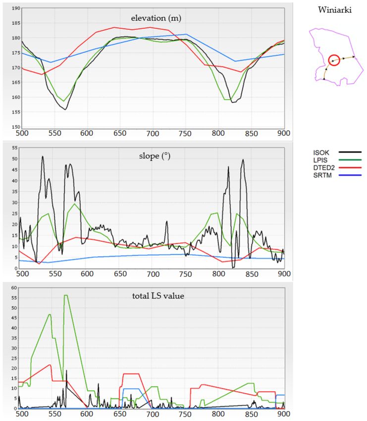
Remote Sens. 2021, 13, 678                                                                                                      8 of 37

      Figure 2. Janowice research area: slope map with hill shade effects (data source: ALSdigital terrain model (DTM) processing—
      1 m × 1 m spatial resolution) (a) and water erosion risk based on The Institute of Soil Science and Plant Cultivation (IUNG)
      expert classification from level 0—no risk to level 5—very high risk and 40 m × 40 m spatial resolution (b).

      Figure 3. Winiarki research area: slope map with hill shade effects (data source: ALS DTM processing—1 m × 1 m spatial
      resolution) (a) and water erosion risk based on the IUNG expert classification from level 0—no risk to level 5—very high
      risk: 40 m × 40 m spatial resolution (b).

                                       The research area of Bolcie covers an area of 501 ha and is located in the northern
                                  part of the East Suwałki Lake District. The north-western part of the area border coincides
                                  with the Polish and Lithuanian borders. The terrain altitudes (ALS data) vary from 206 m
                                  above sea level up to 273 m above sea level. The slope values in this area (ALS data) reach
                                  up to 59◦ (Figure 4a). The land is mainly covered by grasslands and agricultural crops
                                  (89.9%), forests and wooded areas (5.8%), water bodies (3.0%) and built-up areas (1.1%)
                                  (based on the BDOT10k topo reference database). As already mentioned, the selection
                                  of research areas was preceded by an analysis of the water erosion risk in these areas
                                  (Figures 2b, 3b and 4b).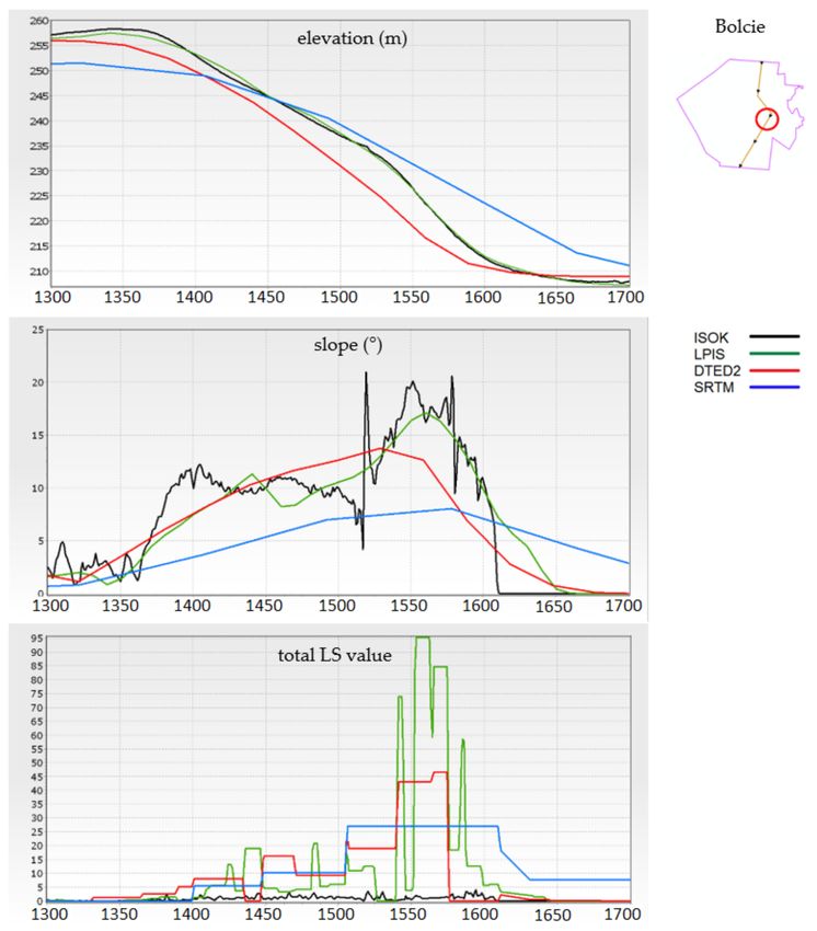
Remote Sens. 2021, 13, 678                                                                                                      9 of 37

      Figure 4. Bolcie research area: slope map with hill shade effects (data source: ALS DTM processing—1 m × 1 m spatial
      resolution) (a) and water erosion risk based on the IUNG expert classification from level 0—no risk to level 5—very high
      risk: 40 m × 40 m spatial resolution (b).

                                 2.2. DTM Source Data
                                      At present, a wide range of DTM and digital surface model (DSM) data is available
                                 nationwide (homogeneous data for the territory of Poland). These data were created as
                                 a result of the use of various technologies; therefore, they are characterised by varying
                                 accuracies and details of mapping the terrain forms, varying spatial resolutions resulting
                                 from these parameters, as well as varying validities. The list of the most frequently used
                                 data sources is presented in Table 2.

      Table 2. Summary of the commonly used elevation data for the area of Poland. DTM: digital terrain model and DSM: digital
      surface model.

                                                                                      Spatial Resolution
      Dataset Name             Model Type           Absolute Height Accuracy                                      Up-to-Date
                                                                                      (GRID Structure)
          SRTM                     DSM                     1.6 m–7.2 m                   30 m / 90 m                  2000
      FDEM / HDEM                                          0.8 m/4–8 m                       6m                     2017 [97]
          IDEM                     DSM                        2 m [98]                      12 m                   2010–2015
        TanDEM-X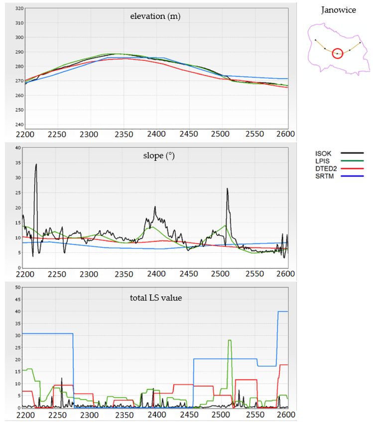
Remote Sens. 2021, 13, 678                                                                                            10 of 37

                             University of Technology, it was estimated that the accuracy of the height determination
                             for the areas around Warsaw is 2 to 3 m.
                                  The LPIS DTM is mainly used to generate orthophotomaps for ARMA (Agency for
                             Restructuring and Modernisation of Agriculture). Aerial photos in the scale of 1:26,000 and
                             topographic maps of 1:10,000 for inaccessible (mainly forest) areas were used for its con-
                             struction, and new data was obtained in accordance with the data update ARMA schedule.
                             This model has a height accuracy of 1 m–1.5 m. It is possible to obtain free-of-charge data
                             from The National Geodesy and Cartographic Resources (PZGiK). It is recommended to
                             generate raster DTM with 10-m spatial resolution from the LPIS source data.
                                  In 2010, the implementation of the ISOK project aimed at preventing crises in flood
                             zones was started in Poland. As part of the project, point clouds in the technology of
                             airborne laser scanning (ALS) were obtained. The source measurement data are stored in
                             the form of a classified point clouds with a density depending on the degree of land use
                             from 4 points/m2 (standard I) to 12 points/m2 (standard II). As a rule, the data in standard
                             I should meet the accuracy assumptions of the mean error of the x and y coordinates:
                             mx, y < 0.5 m and the z coordinate: mz < 0.15 m, while the data in standard II should meet
                             the accuracy assumptions of the mean error of the x and y coordinates: mx, y < 0.4 m and
                             the z coordinate: mz < 0.10 m [101]. Measurement data, as well as the raster forms of DTM
                             and DSM, can be obtained free-of-charge from the PZGiK resource. It is recommended
                             to generate raster DTM from the ISOK source data with 0.5-m or 1-m spatial resolution,
                             depending on the standard (II or I). This resolution is sufficient to reflect the relief of the
                             terrain with sufficient detail for hydrological studies [90].
                                  The elevation source data was selected so that, in the raster form, they present the
                             sequence of spatial resolution: from 90 m to 1 m (resulting from the accuracy and detail
                             of the source data), as well as different techniques of data acquisition and different ones
                             up-to-date. The selected DTMs were acquired on the following dates: SRTM (2000), DTED2
                             (1980), LPIS (05.2008–06.2009) and ISOK (10.2011–04.2012). Due to the fact that the analysis
                             carried out in this project concerned agriculture areas, the problem of the different validities
                             of the data and model types (DTM/DSM) was considered negligible. All DTM data were
                             preprocessed (e.g., sinks filling or raster snapping) for being as suitable as possible for
                             further analysis.

                             2.3. USLE/RUSLE LS Formulas Implementation
                                  As mentioned in the introduction, few authors have attempted to compare the results
                             of water erosion modelling by testing various data sources for individual criteria. The
                             most frequently used methodologies assume either the study of a new data source or
                             introduction of new approaches to determining the value of one of the factors or the entire
                             model by comparing the obtained new results with the results obtained on the basis of
                             previously used data or technologies [38,42,43,102–105] or comparing these with the results
                             obtained using the methodology used so far [17,19,30,36,48,55,106].
                                  The examples of assessing the influence of spatial resolutions of the DTM on the values
                             of DTM derivatives, including the values of the L and S USLE/RUSLE factors [58,88,95,96]
                             found in the literature review, assumed performing tests with the use of a single DTM
                             source with increasingly lower resolutions, obtained by degrading the resolution of the
                             original DTM of high spatial resolution as an adopted methodology. On the other hand,
                             this project assumed the use of various original data sources available for the territory of
                             Poland, which differ in both spatial resolution (resulting from the accuracy and detail of
                             the source data) and the technology of the data acquisition. Initial data processing showed
                             that, despite the similarity of the elevation values, the values of DTM derivatives differ
                             significantly between individual datasets. Therefore, the presented methodology includes
                             not only an analysis of the value of the L and S factors obtained from different source data
                             but, also, a comparative analysis of the DTM values and the values of the land slopes.
                                  For this reason, the proposed methodology consists of the following steps:
Remote Sens. 2021, 13, 678 11 of 37
• stage 1 determination of the mask of agricultural areas inside the research areas (exclu-
sion of nonagricultural part from statistics calculation),
• stage 2 detailed comparative analyses of elevation values and slope values obtained
from various DTM source data,
• stage 3 calculation of the values of the L and S factors in accordance with the adopted
formulas and with use of various DTM source data and
• stage 4 detailed analyses of the total value of the LS factors obtained from different
DTM source data.
The values of basic statistics (minimum, maximum, arithmetic mean, standard de-
viation, median and range) were used to compare the values of elevation, slopes and
LS factors.
The first step (stage 1) was to determine the mask of agricultural areas within the
boundaries of the research areas. Although the calculation of the values of the L and S
factors was performed for the entire studied areas, the comparison of the obtained values
was carried out only within the area of agricultural use. This is supported by the fact
that water erosion is primarily a threat to arable soils, and the research conducted mainly
focused on predicting and preventing erosion in these areas. The second premise results
from the previously mentioned specificity of the data used. SRTM data is defined as a
digital surface model (DSM), and that is why comparing its derivatives with derivatives
obtained from other DTM sources in wooded areas carries the risk of obtaining different
processing results. This mask was developed on the basis of data provided by ARMA.
All statistics for DTM data and their derivatives were developed to facilitate a pos-
sibility of comparing the obtained results on the basis of the values assigned to points
(vector layer) distributed within the study areas in a regular grid of 1 m × 1 m. Thus, for
the results obtained from all DTM sources, the number of observations in each research
area is the same. Moreover, this approach guarantees a comparison of the values obtained
in exactly the same locations.
The methodology of the comparative analysis of DTM (after preprocessing, e.g., sink
filling) and slopes values (stage 2) is presented in Figure 5.
Figure 5. The methodology of a comparative analysis of the DTM and slopes values (stage 2).
The next stage (stage 3) of the study was the calculation of the values of the L factor
and the S factor depending on the DTM data source used for the calculations, as well as
comparison of the obtained values. An indication of the formulas used and the subsequent
analysis included in this stage are presented in Figure 6.Remote Sens. 2021, 13, 678 12 of 37
Figure 6. The methodology of calculating and comparing the values of the slope length (L) and
steepness (S) factors (step 3).
When determining the influence of the L and S factors on the water erosion estima-
tion, many authors, referring to the USLE/RUSLE methodology, do not always carry out
calculations according to the same assumptions and formulas. The choice of the formulas
described by the equations presented in the scheme for the implementation of this stage
(Figure 6) was based on the assumption that the equations should contain as few fixed val-
ues and simplifications as possible (e.g., assuming a specific value of one of the parameters
for a specific range of slopes). These formulas were also selected by researchers from the
Joint Research Centre (JRC)—European Soil Data Centre (ESDAC) [26,29,32,35,41,43,68,92].
The RUSLE2015 project to designate the areas of water erosion risk for EU countries also
used them [40,42]. In this study, the simplest single-flow algorithm (D8) was used to
calculate the unit slope contribution areas to minimise the impact of the division of the
runoff paths or a random factor on the calculation results.
The next stage (stage 4) of the performed analysis consisted of an in-depth analysis of
the value of the total impact of the L and S factors, calculated as the multiplication of their
values (LS) (Figure 7).
Figure 7. The methodology of the comparative analysis of the total LS factors value (stage 4).Remote Sens. 2021, 13, 678 13 of 37
Then, the total LS value threshold for 95% and 99% of the pixels were determined
and compared with the maximum values of each of the datasets. The threshold values are
understood to be the limit values within which 95% and 99% of the agricultural land in
each research area falls, respectively. The significant difference in the value between the
threshold value and the maximum value for research indicates the presence of small areas
with very high values of the total LS factor values, interpreted as an indicator of the places
most exposed to erosion due to their topography.
In the next step of stage 4, the calculated LS values from DTMs with lower resolutions
were compared to the LS value calculated from ISOK. The Pearson correlation coefficients
were calculated for all pairs of results and the scatter plots for the least and most correlated
pairs of the total LS factors values analysed. At the end of this stage, the following statistical
values relating to the area of the entire agricultural plot were calculated: the sum, standard
deviation, mean, median and the maximum of the total LS factors value.
The comparison of the total LS factors values calculated from ISOK and other DTM
sources in agricultural plots was carried out by calculating the value of the variability index
WZ (Equation (2)). This indicator shows what effect the calculation of the total LS factors
values with DTMs of lower accuracy and detail would have on the final value obtained
from the USLE/RUSLE equation. The lowest values (close to 0) indicate a significant
underestimation of the total LS factors values relative to ISOK, while very high values, a
significant overestimation of the value of the total LS factors values relative to ISOK. The
values of the WZ variation index ranging from 0.9 to 1.1 (±10%) were considered to be the
values comparable to those obtained from ISOK.
LSSUM i
Wz = (2)
LSSUM ISOK
where:
LS SUM i : the total value of LS factors obtained for the agricultural plot based on SRTM,
DTED2 and LPIS;
LS SUM ISOK : the total value of LS factors obtained for the agricultural plot based on ISOK.
The analysis that complements the described calculations is the visualisation of the
DTM elevation value, land slopes and the total LS factors values along the selected terrain
profiles. Localisations of the profiles were selected so that they pass through areas with a
significant diversification of reliefs and slopes. The comparison of the profiles showed to
what extent the DTM data and their derivatives (slopes and total LS factor values) exhibited
similarities or differences inside the 3 research areas.
3. Results
3.1. DTM Elevation and Slopes Comparison
A statistical analysis of the elevations in the individual research areas shows that
there is a significant similarity of the elevation values in the analysed DTM obtained from
four sources. The basic statistics of the DTM values for the research areas are presented
in Table 3. Despite the significant differences in accuracy and detail, the comparative
analysis of the DTM data shows that the distribution of elevation values is very similar.
This is evidenced by the similarity of the histograms and by the high values of the Pearson
correlation coefficients. Those values calculated for all DTM pairs are surprisingly high,
with the greatest similarity in all research areas shown by the ISOK and LPIS data—the
value of the correlation coefficient does not fall below 0.99. The lowest correlation was
noted for the DTED2 and SRTM data, but still, the values are not lower than 0.93 (Table 4).
Such high values of the Pearson coefficients are also confirmed by the analysis of the scatter
plots for the DTM pairs; the closest agreement was obtained for the ISOK and LPIS data,
but for all the compared DTM pairs, the points representing the pixel values of the two
datasets are arranged closely along the regression line.Remote Sens. 2021, 13, 678 14 of 37
Table 3. Summary of the basic statistics characterising the elevations for all the DTM sources in the 3 research areas.
Data Source Min Max Mean Median Standard Deviation Range Min-Max
Janowice
SRTM 198 410 285.5 288 54.7 212
DTED2 202 416 287.1 289 53.8 214
LPIS 200.2 418.1 287.5 289.6 54.3 218
ISOK 201.0 418.0 287.4 289.4 54.3 217
Winiarki
SRTM 135 199 175.4 183 18.7 64
DTED2 139 206 178.3 184 18.9 67
LPIS 139.1 204.6 178.8 186.2 19.7 66
ISOK 138.6 205.2 179.4 186.8 19.7 67
Bolcie
SRTM 204 260 238.8 241 11.9 56
DTED2 207 264 241.3 244 12.8 57
LPIS 205.4 264.4 241.0 243.6 12.7 59
ISOK 206.0 266.5 241.7 244.5 12.7 61
Table 4. Comparison of the DTM Pearson correlation coefficient values for all DTM sources in the 3 research areas.
Janowice
ISOK LPIS DTED2 SRTM
ISOK 1.000 1.000 0.998 0.991
LPIS 1.000 0.998 0.992
DTED2 1.000 0.989
SRTM 1.000
Winiarki
ISOK LPIS DTED2 SRTM
ISOK 1.000 0.998 0.972 0.967
LPIS 1.000 0.975 0.969
DTED2 1.000 0.956
SRTM 1.000
Bolcie
ISOK LPIS DTED2 SRTM
ISOK 1.000 0.998 0.978 0.942
LPIS 1.000 0.979 0.949
DTED2 1.000 0.933
SRTM 1.000
Despite the very high values of the correlation coefficients, the elevation differences
(∆z) of LPIS, DTED2 and SRTM compared to ISOK are significant. For the less-correlated
pair (ISOK and SRTM), they reached a maximum of −34.5 m (the elevation of the ISOK
is smaller) and 36.3 m (the elevation of the ISOK is higher) for the agricultural areas.
Even a comparison of the DTM values for the most correlated ISOK and LPIS pair shows
differences on average of ±0.9 m in all research areas (Table 5).
Table 5. Comparison of the differences in the elevation values from DTM of lower accuracy and detail (SRTM, DTED2 and
LPIS) to ISOK (minimum, maximum and mean of the absolute value |∆z| of the differences).
ISOK-SRTM (m) ISOK-DTED2 (m) ISOK-LPIS (m)
min max mean min max mean min max mean
Research Area
∆z ∆z |∆z| ∆z ∆z |∆z| ∆z ∆z |∆z|
Janowice −34.5 36.3 ± 5.8 −27.3 22.1 ± 2.5 −11.0 14.0 ± 0.7
Winiarki −24.4 34.5 ± 5.4 −23.4 35.3 ± 3.0 −14.0 12.7 ± 1.0
Bolcie −22.4 25.1 ± 4.1 −13.1 20.5 ± 2.0 −6.0 7.9 ± 0.9Remote Sens. 2021, 13, 678 15 of 37
A statistical analysis of the slope values in individual research shows that there is much
less similarity in the value of this DTM derivative than in the case of the elevation values in
the four analysed DTM sources. Basic statistics (Table 6) clearly shows that the maximum
slope values increase with the increase of the DTM accuracy and detail (understood as the
analysis of changes in the DTM derivative values for the series: SRTM → DTED → LPIS
→ ISOK). This is a significant change, with the maximum values increasing more than six
times between SRTM and ISOK. At the same time, the average value of the slopes and
the median grow—this statistical measure is subject to less fluctuations than the average,
which means that, although the maximum value increases, high values of landfalls do not
occur in a large part of the study area. The greater variability of slope values in the research
areas is also evidenced by the increase in the value of the standard deviation along with
the increase in the accuracy and detail of the analysed DTM data.
Table 6. Summary of the basic statistics of the slope values (◦ ) in the 3 research areas.
Data Source Min Max Mean Median Standard Deviation Range Min-Max
Janowice
SRTM 0.0 16.4 6.5 7.1 3.3 16.4
DTED2 0.0 27.4 7.9 8.2 4.3 27.4
LPIS 0.0 41.5 8.6 8.7 5.1 41.5
ISOK 0.0 65.9 9.4 8.8 6.5 65.9
Winiarki
SRTM 0.0 12.0 2.8 2.2 2.0 12.0
DTED2 0.0 32.2 6.2 4.6 5.6 32.2
LPIS 0.0 39.0 6.2 4.5 5.9 39.0
ISOK 0.0 73.0 7.5 4.8 8.1 73.0
Bolcie
SRTM 0.0 8.7 2.6 2.0 1.9 8.7
DTED2 0.0 18.1 4.2 3.5 3.0 18.1
LPIS 0.0 32.0 5.2 4.3 4.0 32.0
ISOK 0.0 58.7 6.3 5.1 5.4 58.7
The values of the Pearson correlation coefficients of the slope values decrease in
comparison to the values of the coefficients calculated for the terrain elevations (DTM
values). The slopes calculated on the basis of ISOK and LPIS show the greatest similarity
in all research areas—the values of the correlation coefficients do not fall below 0.75. The
lowest correlation was recorded for the slopes in the ISOK and SRTM pair; the coefficient
values are already lower and range from 0.36 (Bolcie study area) to 0.52 (Janowice study
area) (Table 7).
An analysis of the histograms of the terrain slope values also confirms the significant
variability in the distribution of the values, with an increase in the accuracy and detail of
the DTM. The presence of a few pixels with relatively high slope values in each dataset
was noticed (Table 8). The greater the accuracy and detail of the source data, the higher the
maximum slope values. The maximum differences in the slope values (∆s) are significant
for all DTM pairs. The largest positive differences (the slope of the terrain calculated on the
basis of ISOK data has a greater value) are analogically high for all the compared DTMs
and range, on average, from 55◦ for ISOK and LPIS pair to 60◦ for ISOK and SRTM pair.
Unexpectedly, the greatest negative differences (the slope of the area calculated on the basis
of the data from ISOK has a lower value) were obtained for the ISOK and LPIS pair: −40.4◦
for the Janowice research area. The mean values of the absolute differences (|∆s|) do not
differ significantly between the individual DTM pairs, ranging from ±2.6◦ for the ISOK
and LPIS pair to ±4.6◦ for the ISOK and SRTM pair (Table 9).Remote Sens. 2021, 13, 678 16 of 37
Table 7. Comparison of the Pearson correlation coefficients of the slope values (◦ ) calculated on the
basis of the 4 sources of DTMs in the 3 research areas.
Janowice
ISOK LPIS DTED2 SRTM
ISOK 1.000 0.750 0.605 0.515
LPIS 1.000 0.792 0.682
DTED2 1.000 0.735
SRTM 1.000
Winiarki
ISOK LPIS DTED2 SRTM
ISOK 1.000 0.753 0.536 0.393
LPIS 1.000 0.669 0.523
DTED2 1.000 0.559
SRTM 1.000
Bolcie
ISOK LPIS DTED2 SRTM
ISOK 1.000 0.748 0.476 0.363
LPIS 1.000 0.656 0.516
DTED2 1.000 0.659
SRTM 1.000
Table 8. Comparison of the range of the slope values and the slope maximum threshold values (◦ )
for 95% and 99% of pixels in the research areas.
Janowice
threshold SRTM DTED2 LPIS ISOK
95% of research area 11.3 14.6 16.8 20.5
99% of research area 12.9 17.3 19.9 28.1
maximum value 16.4 27.4 41.5 65.9
Winiarki
threshold SRTM DTED2 LPIS ISOK
95% of research area 6.9 17.1 17.1 23.1
99% of research area 8.4 23.1 24.2 37.7
maximum value 12.0 32.2 39.0 73.0
Bolcie
threshold SRTM DTED2 LPIS ISOK
95% of research area 6.1 10.2 12.8 16.1
99% of research area 7.7 14.5 17.1 24.9
maximum value 8.7 18.1 32.0 58.7
Table 9. Comparison of differences in the values of the terrain slopes (∆s) (◦ ) calculated on the basis of DTM (SRTM,
DTED2 and LPIS) against ISOK (minimum, maximum and the mean of the absolute value |∆s| of the differences) in the 3
research areas.
ISOK-SRTM (◦ ) ISOK-DTED2 (◦ ) ISOK-LPIS (◦ )
Research Area min max mean min max mean min max mean
∆s ∆s |∆s| ∆s ∆s |∆s| ∆s ∆s |∆s|
Janowice −15.7 60.6 ± 4.2 −26.0 61.5 ± 3.5 −40.4 58.9 ± 2.7
Winiarki −10.2 68.9 ± 5.2 −28.9 66.8 ± 4.2 −35.1 60.0 ± 2.9
Bolcie −8.7 51.7 ± 4.3 −15.0 49.8 ± 3.5 −24.8 47.7 ± 2.3
When analysing the distribution of the ∆s values, the greatest values are observed in
the middle and lower parts of steepest slopes. Panagos [40] mentioned that the vast majority
of areas in Europe have slope values of up to 50% (approx. 26.6◦ ). This is confirmed by theRemote Sens. 2021, 13, 678 17 of 37
results obtained for the research areas, but only if the results of the analysis using DTM
data of similar accuracy and detail are compared (the analyses described in the article were
carried out using EU-DEM with a spatial resolution of 25 m). The values obtained for the
research areas for the DTED2 slope maps reach 29◦ , while, for DTM with higher accuracy
and detail, the maximum values for the Janowice area (foothills) reach 46◦ (for LPIS DTM)
and 78◦ (for ISOK DTM).
3.2. Comparison of the Total LS Factors Values
The specificity of the universal soil loss equation USLE/RUSLE results in the fact that
the influence of the variability of the values of the L and S factors on the value of soil loss
due to water erosion is multiplied. The total influence of the L and S factors in the soil
loss equation is determined as the multiplication of their values (L * S). The first part of
comparing the total LS factors values was to compare the results for each pixel (1 m × 1
m grid). The second part was to compare the statistical values after aggregating for the
agricultural plots. For individual research areas, the maximum LS range was obtained up
to the value of 3314.9 (for the Janowice research area) to 824.3 (for the Winiarki research
area) and to 1116.8 (for the Bolcie research area); the higher values were obtained based on
ISOK DTM data (Table 10).
Table 10. Summary of the basic statistics for the total length/steepness (LS) factors values in the 3
research areas.
Data Source Min Max Mean Median Standard Deviation
Janowice
SRTM 0 160.6 16.4 8.8 21.6
DTED2 0 257.5 11.9 7.4 15.8
LPIS 0 500.6 6.0 3.1 10.0
ISOK 0 3314.9 1.0 0.2 7.1
Winiarki
SRTM 0 54.3 1.5 0.0 3.5
DTED2 0 219.7 4.9 0.1 13.9
LPIS 0 273.6 2.4 0.5 5.9
ISOK 0 824.3 0.5 0.1 3.1
Bolcie
SRTM 0 47.1 2.4 0.0 4.9
DTED2 0 258.2 3.3 0.7 9.2
LPIS 0 297.2 2.2 0.7 5.7
ISOK 0 1116.8 0.5 0.1 3.4
In all the research areas, the maximum values of the total LS factor values increase
consistently with the increasing accuracy and detail of the DTM source data. In the research
area of Janowice, the mean and median values, as well as standard deviation, clearly
decrease, along with the increase in the accuracy and detail of the source data. There is
no such relationship in the Winiarki and Bolcie research areas, and the mean values and
standard deviation are the highest for the LS calculated from the DTED2 data.
This is confirmed by the analysis of the terrain profiles presented in Figure 8 and in
Appendix B. A comparative analysis of the elevation profiles indicates that, along with
a decrease in the accuracy and detail of DTM, a process of flattening of the valleys takes
place, which leads to a decrease in the length and steepness of the slope represented by
the generalised source data compared to the high-resolution data. Along with the increase
in the accuracy and detail of the DTM, a significant increase in the area with the total
LS factor values close to 0 is noticed. This is evidenced by the total LS factor threshold
values obtained for 95% and 99% of the area. The highest threshold values in the Janowice
research area were observed for SRTM derivatives and, in the Winiarki and Bolcie research
areas, for the DTED2 derivatives (Table 11). There is a significant discrepancy between theRemote Sens. 2021, 13, 678 18 of 37
total LS factors threshold values for 95% and 99% of the area and the maximum of the total
LS values, and this discrepancy increases with the increasing accuracy and detail of the
source DTM.
Figure 8. Visualisation of the elevation (m), slopes (◦ ) and the total LS factor values (Y-axis) calculated
from all the DTM sources for a selected section of the profile (over a 400-m section) of the Winiarki
research area (additional visualisations for Janowice and Bolcie research areas are presented in
Appendix B).
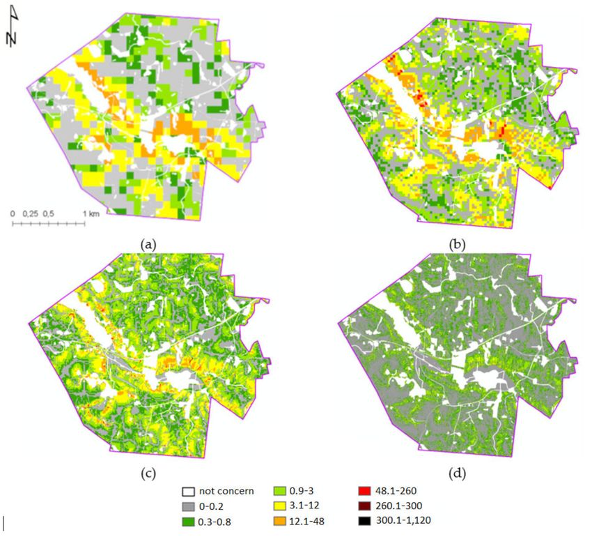
The analysis of the spatial distribution and the histograms of the total LS factor values
shows that the largest range of the areas with the lowest values was obtained for the results
calculated on the basis of the ISOK data (Figure 9). Areas with values ranging from 0 to 1
occupy an average of 60% of the research areas for the results obtained from SRTM and
88% of the research areas for the results obtained from the ISOK data.Remote Sens. 2021, 13, 678 19 of 37
Table 11. Comparison of the maximum of the total LS factor threshold values for 95% and 99% of the
area in the 3 research areas.
Janowice
threshold SRTM DTED2 LPIS ISOK
95% of research area 58.5 38.4 20.0 3.4
99% of research area 84.7 62.8 37.5 9.8
maximum value 160.6 257.5 500.6 3314.9
Winiarki
threshold SRTM DTED2 LPIS ISOK
95% of research area 8.3 22.4 9.7 1.7
99% of research area 17.2 51.7 20.4 4.6
maximum value 54.3 219.7 273.6 824.3
Bolcie
threshold SRTM DTED2 LPIS ISOK
95% of research area 11.6 13.5 8.0 1.6
99% of research area 18.6 27.4 17.1 3.9
maximum value 47.1 258.2 297.2 1116.8
Figure 9. Visualisation of the total LS factor values (classes) based on SRTM (a), DTED2 (b), LPIS
(c) and ISOK (d) for the Bolcie research area (additional visualisations for Janowice and Winiarki
research areas are presented in the Appendix A).
The analysis of the values of the Pearson correlation coefficients (Table 12) and the
scatter plots indicates a significant lack of similarity of the total LS factors values obtained
for the pairs of different DTM sources. Still, the lowest correlation values were obtained
for the ISOK and SRTM pair—the Pearson coefficient value does not exceed 0.08 in all theRemote Sens. 2021, 13, 678 20 of 37
research areas and indicates a complete lack of similarity of these datasets. The maximum
value of the correlation coefficient was obtained for the DTED2 and SRTM pair for the
Bolcie and Winiarki research areas, but it is still only a maximum of 0.44.
Table 12. Summary of the Pearson correlation coefficients for the total LS factor values calculated on
the basis of 4 DTM sources in the 3 research areas.
Janowice
ISOK LPIS DTED2 SRTM
ISOK 1.000 0.086 0.065 0.050
LPIS 1.000 0.321 0.257
DTED2 1.000 0.444
SRTM 1.000
Winiarki
ISOK LPIS DTED2 SRTM
ISOK 1.000 0.128 0.068 0.037
LPIS 1.000 0.118 0.108
DTED2 1.000 0.215
SRTM 1.000
Bolcie
ISOK LPIS DTED2 SRTM
ISOK 1.000 0.139 0.066 0.077
LPIS 1.000 0.237 0.274
DTED2 1.000 0.378
SRTM 1.000
The distribution of the values in the profiles showing the total LS factors confirms
the previously described discrepancy in the values calculated on the basis of different
DTMs. In most cases, it is difficult to find the convergence of the local maximums and
minimums in the graphs. There is also a noticeable, though less visible in the previously
analysed statistics, overestimation of the total LS values obtained on the basis of the LPIS
data—much more noticeable in the research areas of Winiarki and Bolcie. The profiles of
all the compared features (elevation, slopes and the total of the LS factors values) for each
of the research areas are presented in Figure 8.
3.3. Comparison of the Total Values of the LS Factors in Agricultural Plots
The next stage was an analysis of the total LS factor values after aggregating the results
in the agricultural areas (plots) designated on the basis of the data provided by ARMA. For
all the agricultural plots, the LS statistical values were calculated relating to the area of the
whole plot: sum, standard deviation, mean, median and maximum values. These values
are presented in Table 13. Visualisation of the changes in the value of the sum of the total
LS factor values in the plot and the maximum value of the total LS factor values in the plot
are presented in Figures 10 and 11.Remote Sens. 2021, 13, 678 21 of 37
Table 13. Summary of the statistics of the total LS factor values (sum, standard deviation, mean,
median and maximum values) for the agriculture plots in the 3 research areas.
Data Source Maximum Value Standard Deviation Sum Mean Median
Janowice
SRTM 160.6 8.0 113553 16.8 15.8
DTED2 257.5 7.8 86158 12.1 10.7
LPIS 500.6 6.3 43231 5.8 4.1
ISOK 3314.9 4.7 7426 1.0 0.2
Winiarki
SRTM 54.3 2 9613 2.2 1.9
DTED2 219.7 8.5 32781 4.2 2.6
LPIS 273.6 3.6 15761 1.9 1.1
ISOK 824.3 2.3 3061 0.4 0.1
Bolcie
SRTM 47.1 1.8 51 378 2.6 2.2
DTED2 258.2 3.8 69 438 3.6 2.4
LPIS 297.2 3.1 45 083 2.2 1.3
ISOK 1116.8 1.9 10 178 0.5 0.2
Figure 10. Visualisation of the sum of the total LS factors values in agriculture plots based on SRTM
(a), DTED2 (b), LPIS (c) and ISOK (d) of the Bolcie research area.Remote Sens. 2021, 13, 678 22 of 37
Figure 11. Visualisation of the maximum of the total LS factor values in the agriculture plots based
on SRTM (a), DTED2 (b), LPIS (c) and ISOK (d) of the Bolcie research area.
Visualisations of the total LS factor values for the individual plots (Figures 10 and 11)
in all the research areas show:
• a decrease in the value of the sum of the total LS factor values in the plot,
• a decrease in the percentage of plots with high values of the sum of the total LS factor
values and
• a significant increase in the maximum of the total LS factor values in the plot as the
accuracy and detail of the source DTM increases.
The obtained values of the Pearson correlation coefficients for the plots indicate a
significant increase in the similarity of the total LS factor values analysed in the areas of the
agricultural plots in relation to the analysis of the values at the points placed in the regular
grid (1 m × 1 m). The highest agreement was obtained for the sum of the total LS factors
values in the plot for the ISOK and LPIS pair; in all the research areas, it is a very high
similarity—the values of the correlation coefficients have a value of approx. 0.96. Even for
the pair of ISOK and SRTM, although the lowest, they range from 0.52 to 0.78 (Table 14).
Significantly lower values of the Pearson correlation coefficients were obtained when
comparing the maximum values in the agricultural plots. These values significantly differ
from each other, and the highest correlation occurs for the DTED2 and SRTM pair at the
level of 0.43–0.63 and the lowest for the ISOK and SRTM pair at the level of 0.07–0.49
(Table 15).
The difference in the total LS factors values in an agricultural plot is indicated by
the results of the variation index Wz, which was used to compare the LS values obtained
from the SRTM, DTED2 and LPIS data with the LS values obtained from the ISOK data
(Equation (2)).Remote Sens. 2021, 13, 678 23 of 37
Table 14. The summary of the Pearson correlation coefficient values for the sum of the total LS values
calculated on the basis of the 4 DTM sources for the agricultural plots in the 3 research areas.
Janowice
ISOK LPIS DTED2 SRTM
ISOK 1.000 0.959 0.874 0.733
LPIS 1.000 0.887 0.750
DTED2 1.000 0.825
SRTM 1.000
Winiarki
ISOK LPIS DTED2 SRTM
ISOK 1.000 0.967 0.715 0.519
LPIS 1.000 0.713 0.608
DTED2 1.000 0.596
SRTM 1.000
Bolcie
ISOK LPIS DTED2 SRTM
ISOK 1.000 0.965 0.793 0.784
LPIS 1.000 0.818 0.812
DTED2 1.000 0.794
SRTM 1.000
Table 15. The summary of the Pearson correlation coefficient values for the maximum of the total LS
factor values on the basis of the 4 DTM sources for the agriculture plots in the 3 research areas.
Janowice
ISOK LPIS DTED2 SRTM
ISOK 1.000 0.256 0.219 0.150
LPIS 1.000 0.483 0.422
DTED2 1.000 0.605
SRTM 1.000
Winiarki
ISOK LPIS DTED2 SRTM
ISOK 1.000 0.337 0.266 0.068
LPIS 1.000 0.384 0.221
DTED2 1.000 0.426
SRTM 1.000
Bolcie
ISOK LPIS DTED2 SRTM
ISOK 1.000 0.544 0.499 0.487
LPIS 1.000 0.601 0.629
DTED2 1.000 0.628
SRTM 1.000
As already mentioned in the description in the Methodology section, very low values
of the Wz index (close to 0) indicate a significant underestimation of the total LS factor
values relative to ISOK; in turn, very high Wz values indicate a significant overestimation
of the total LS factors values relative to ISOK. The values of the similarity index ranging
from 0.9 to 1.1 (±10%) were considered as values comparable to those obtained from ISOK.
The comparison of the sums of the total LS factor values in the agriculture plots calculated
on the basis of SRTM, DTED2 and LPIS against the sums of the total LS factors values
calculated on the basis of ISOK for the three research areas is presented in Table 16.Remote Sens. 2021, 13, 678 24 of 37
Table 16. Comparison of sum of the total LS factors values in the agriculture plots calculated on the basis of the DTMs
SRTM, DTED2 and LPIS against the sum of the total LS factors values calculated on the basis of the DTM ISOK in the 3
research areas (in %).
Janowice Bolcie Winiarki
SRTM DTED2 LPIS SRTM DTED2 LPIS SRTM DTED2 LPIS
% of values lower than ISOK 9.2 1.0 0.6 27.6 2.9 2.3 15.3 1.9 0.2
% of values equal to ISOK 0.9 0.6 0.6 5.3 1.0 1.7 3.7 1.1 0.1
% of values higher than ISOK 89.9 98.4 98.8 67.1 96.1 95.9 81.0 97.0 99.7
The calculated values of the coefficient of variation Wz range from 0.001 (the total LS
factor values with SRTM were 1000 times lower than the value obtained from ISOK) to 475
(the total LS factor values from SRTM were 475 times higher than the value obtained from
ISOK). Both extreme values were obtained for the Janowice research area. The greatest
differences were noticed when comparing the total LS factor values obtained from SRTM
with the values obtained from ISOK. The analysis of these values revealed a significant
percentage of the areas with an underestimation the total LS factors values; in all the
research areas, it is a significant part of the area (Table 16). This relationship is also visible
in the visualisations of the distribution of the WZ variability index (Figure 12) calculated
for the total LS factors values with DTED2 and ISOK, as well as LPIS and ISOK.
Figure 12. Comparison of the values of the variability index Wz for the sum of the total LS factor
values in the plots used for agriculture obtained from the DTM SRTM (a), DTED2 (b) and LPIS (c)
against ISOK for the Bolcie research area (additional visualisations for the Janowice and Winiarki
research areas are presented in Appendix C).
The blue tones show plots with the total LS factors values underestimated in relation
to ISOK; grey is comparable values and colours: yellow, orange and red are overestimatedRemote Sens. 2021, 13, 678 25 of 37
values in relation to ISOK. Plots in blue tones are scarce. The highest values of the Wz
coefficient (the highest overestimation of the total LS factors values in relation to ISOK)
were obtained by comparing the total LS factors values calculated with SRTM and ISOK
and with DTED2 and ISOK (the Janowice and Winiarki research areas) and with DTED2
and ISOK (the Bolcie research area), which is visible in the visualisations of the Wz values
distribution—the yellow, orange and red tones have the longest range. The lowest degree
of underestimation and/or overestimation of the values was noted for the Wz coefficient
calculated for the total LS factor values with LPIS and ISOK. The vast majority of the plots
were classified in the coefficient value class with the maximum value of five (maximum
five times overestimation of the total LS factor values in relation to ISOK) or the maximum
value of the coefficient equal to 20 (maximum 20 times overestimation of the total LS factor
values in relation to ISOK), although the share of these classes in the surface area of each
area is different. The obtained values clearly show that, if a DTM with a lower accuracy
and detail than ISOK is used to calculate the LS factor values, one can expect, at best, a
maximum 20 times overestimation of the LS value (for DTM LPIS). Using other models
with lower accuracy and detail, such as DTED2 or SRTM, one can expect an even greater
overestimation and underestimation of the combined effects of both factors.
4. Discussion
Despite the advantages of the models based on the USLE/RUSLE methodology, one
should also be aware of their limitations. Many authors point to the mismatch between
the model and the European conditions. The empirical model was developed for the
eastern part of North America, which, compared to Europe, is characterised by a different
distribution and nature of precipitation, a different landscape and a different distribution
of the dominant hydrological processes. Moreover, the model does not take into account
gully erosion (ephemeral gullies) and crop erosion [10,40,107]. Some researchers report
that comparing the modelling results with the field studies indicates that the USLE/RUSLE
models usually give slightly overestimated values of soil losses or there is a noticeable
overestimation of low values and an underestimation of high values [32,43,69,84]. Another
important problem and challenge in erosion modelling is the assessment of the accuracy of
the obtained results. It is a very difficult and complicated task, as it requires an estimation
of the uncertainty of each of the equation factors, including the L and S factor values [86].
It was also noticed that the modelling results are sometimes inadequate for long slopes of
complicated shapes [107]. The use of a more detailed DTM increases the length of the slopes
and the complexity of their shapes. For a more complete analysis of the impact of DTM
sources on the modelling results, the results obtained with the use of other, multiple-flow
runoff algorithms should also be compared, as well as eroded soil deposition areas, as
indicated by the works [37,60].
The research carried out indicates that the overestimation of total LS value calculated
for the DTM with lower accuracy and detail concerns a much larger area of land than
the underestimation that occurs in relatively small areas. However, the values of the
differences obtained in this case are much higher. This is probably related to the less
accurate determination of the water paths flowing down the slopes and unit upslope
contributing areas using a DTM with less accuracy and detail. The obtained conclusions
confirm the observations of Evans [107], who compared the results of field studies with the
results of modelling using a DTM with low accuracy and detail. He showed that modelling
using the USLE/RUSLE methodology results in the overestimation of values where low
total LS factor values were found in the field and an underestimation of values where high
total LS factor values were found in the field. Moreover, he notes that significantly high
soil losses occur in small fragments of farmland. These observations are confirmed by the
modelling results obtained in this study. With too-low accuracy and detail of the DTM,
high values of the L and S factors are obtained, while, with a DTM with high accuracy
and detail, low values of L and S are actually obtained in most of the area and very high
values in small areas of the field, which indicated the areas of accumulation of runoff onYou can also read


