And High Fuel Efficiency Diesel Engine: Near Zero NO x Emissions
←
→
Page content transcription
If your browser does not render page correctly, please read the page content below
Oil & Gas Science and Technology – Rev. IFP, Vol. 58 (2003), No. 1, pp. 101-114
Copyright © 2003, Éditions Technip

             Near Zero NOx Emissions
       and High Fuel Efficiency Diesel Engine:
  the NADITM Concept Using Dual Mode Combustion
                                                 B. Walter1 and B. Gatellier1
                                1 Institut français du pétrole, division Techniques d’applications énergétiques
                                   1 et 4, avenue de Bois-Préau, 92852 Rueil-Malmaison Cedex - France
                                               e-mail: bruno.walter@ifp.fr - bertrand.gatellier@ifp.fr

           Résumé — Un moteur Diesel avec quasiment zéro émissions de NOx et un rendement élevé : le
           concept NADITM utilisant deux modes de combustion — Grâce à leur bon rendement thermique et à
           leurs faibles émissions de dioxyde de carbone (CO2), les moteurs Diesel verront leur part de marché dans
           les transports croître, à condition que leurs émissions d’oxydes d’azote (NOx) et de particules soient
           réduites. Aujourd’hui, des systèmes de post-traitement adéquat des NOx et des particules sont en passe
           d’être industrialisés. Cependant, des inconvénients subsistent encore en termes de consommation de
           carburant, de fiabilité, de sensibilité au soufre présent dans le carburant et de coût lié à leurs stratégies de
           fonctionnement complexes et sophistiquées.
           De nouveaux procédés de combustion comme la combustion homogène de type HCCI (homogeneous
           charge compression ignition) sont actuellement à l’étude en raison de leur très fort potentiel à atteindre
           des émissions de NOx et de particules quasi nulles. Leurs principaux inconvénients sont des émissions
           d’hydrocarbures imbrûlés (HC) et de monoxyde de carbone (CO) trop élevées, un contrôle de la
           combustion difficile à forte charge et une puissance limitée.
           En réponse au défi que doit relever le moteur Diesel, l’IFP a développé un système de combustion
           capable d’atteindre des émissions de NOx et de particules quasiment nulles tout en conservant les
           standards de performances des moteurs Diesel actuels. Ce concept de moteur “bi-mode” appelé NADITM
           (Narrow Angle Direct Injection) utilise la combustion homogène à charge partielle et bascule en
           combustion traditionnelle pour répondre aux exigences de pleine charge.
           En charges partielles (incluant les cycles MVEG européen et FTP américain), la combustion HCCI
           permet des émissions de NOx et de particules quasi nulles en maintenant un très bon rendement, proche
           d’un moteur Diesel Euro III. À 1500 et 2500 tr/min, le concept NADITM atteint respectivement 0,6 et
           0,9 MPa (6 et 9 bar) de pression moyenne indiquée (PMI) avec des émissions de NOx et de particules
           inférieures à 0,05 g/kWh. Cela représente respectivement 100 et 10 fois moins qu’un moteur Diesel
           traditionnel.
           À pleine charge, le système NADITM est en phase avec les futurs standards de puissance au litre. À
           4000 tr/min, 50 à 55 kW/l ont été atteints avec des conditions limites de fonctionnement et des réglages
           moteur conventionnels.
           L’utilisation de technologies moteur avancées comme la prochaine génération de systèmes d’injection
           common rail, les moteurs à distribution variable (VVA : variable valve actuation), les moteurs à taux de
           compression variable (VCR : variable compression ratio) ou les turbo-compresseurs assistés électri-
           quement sera très utile pour les futures étapes de développement du concept, qui sont bien identifiées.
102 Oil & Gas Science and Technology – Rev. IFP, Vol. 58 (2003), No. 1
Abstract — Near Zero NOx Emissions and High Fuel Efficiency Diesel Engine: the NADITM Concept
Using Dual Mode Combustion — The part of Diesel engines on the transport market should increase
within the years to come thanks to their high thermal efficiency coupled with low carbon dioxide (CO2)
emissions, provided their nitrogen oxides (NOx) and particulate emissions are reduced. At present,
adequate after-treatments, NOx and particulates matter (PM) traps are developed or industrialized with
still concerns about fuel economy, robustness, sensitivity to fuel sulfur and cost because of their complex
and sophisticated control strategy.
New combustion process such as homogeneous charge compression ignition are investigated for their
potential to achieve near zero particulate and NOx emissions. Their main drawbacks are too high
unburned hydrocarbons (HC) and carbon monoxide (CO) emissions, combustion control at high load
and then limited operating range and power output.
As an answer for challenges the Diesel engine is facing, IFP has developed a combustion system able to
reach near zero particulate and NOx emissions while maintaining performance standards of the DI
Diesel engines. This “dual mode” engine application called NADITM (Narrow Angle Direct Injection)
applies homogeneous charge compression ignition at part load and switches to conventional Diesel
combustion to reach full load requirements.
At part load (including Motor Vehicle Emissions Group—MVEG—and Federal Test Procedure—FTP—
cycles), HCCI combustion mode allows near zero particulate and NOx emissions and maintains very
good fuel efficiency close to an Euro III Diesel engine. At 1500 and 2500 rpm, NADITM reaches 0.6 and
0.9 MPa (6 and 9 bar) of indicated mean effective pressure (IMEP) with emissions of NOx and
particulate under 0.05 g/kWh. That means respectively 100 and 10 times lower than a conventional
Diesel engine.
At full load, NADITM system is consistent with future Diesel engine power density standard. At 4000 rpm,
50 to 55 kW/l has been reached with conventional limiting factors and engine parameters settings.
Advanced engine technology such as further generation of common rail fuel injection system, Variable
Valve Actuation (VVA), Variable Compression Ratio (VCR) engine or electric assisted turbocharger will
be useful for the well identified next development steps of the concept.
NOTATIONS Cycle and Norms
EURO III Emission Norm for Europe (2000-2005)
Gas
FTP Federal Test Procedure
CO2 Carbon Dioxide MVEG Motor Vehicle Emissions Group
CO Carbon Monoxide SULEV Super Ultra Low Emission Vehicle.
HC Unburned Hydrocarbons
NOx Nitrogen Oxides Engine Parameters
O2 Oxygen
PM Particulates Matter. A/F ratio Air/Fuel ratio
ATDC After Top Dead Centre
BDC Bottom Dead Centre
Combustion Concepts
BMEP Brake Mean Effective Pressure
HCCI Homogeneous Charge Compression Ignition BMF Burned Mass Fraction
HCDC Homogeneous Charge Diesel Combustion BSFC Brake Specific Fuel Consumption
HiMiCS Homogeneous charge intelligent Multiple BTDC Before Top Dead Centre
injection Combustion System CA Crank Angle
MK concept Modulated Kinetics Concept CFD Computational Fluid Dynamic
NADITM Narrow Angle Direct Injection DI Direct Injection
PCI Premixed Compressed Ignited Combustion EGR Exhaust-Gas Recirculation
PREDIC, PREmixed lean and MULtiple stage DIesel FMEP Friction Mean Effective Pressure
MULDIC Combustion FSN Filter Smoke Number
UNIBUS UNIform BUckly Combustion System. IMEP Indicated Mean Effective PressureB Walter and B. Gatellier / Near Zero NOx Emissions and High Fuel Efficiency Diesel Engine 103
ISFC Indicated Specific Fuel Consumption This concept was developed in 1997 by Hino motors. The
rpm Rotation per minute injection system used is a common rail (with an injection
TDC Top Dead Centre. pressure of 90 MPa), and one single centre injector (6 holes
with a diameter of 0.23 mm and a spray cone angle of 125°
Engine Technology or 30 holes diameter 0.1 mm and three spray cone angles:
12 × 155°, 12 × 105°, 6 × 55°).
FIS Fuel Injection System The injection strategy is divided into four injections: early
VCR/VVA Variable Compression Ratio/Variable Valve injection (called E), pilot injection (P), main injection (M)
Actuation. and late stage injection (A) [16, 17].
• Unibus: Uniform buckly combustion system (Toyota) and
INTRODUCTION PCI: Premixed compressed ignited combustion
(Mitsubishi).
HCCI combustion engines constitute alternative or comple- These two concepts are very close to each other as they
mentary answers to the sophisticated and complex after- use one single centre injector: a piezzo injector with a hollow
treatments strategy, which seems to be compulsory for cone spray (60°) and a spray guide tip (Unibus) and an
classical Diesel engine. Their principle consists in preparing Impinged Spray Nozzle to limit penetration (PCI), and in
a highly diluted by burned gases air/fuel mixture, in both cases, a Common Rail system. The injection timing is
achieving its simultaneous ignition in the whole space of the very early: till 120° BTDC [18-21].
combustion chamber and in precisely controlling such
combustion for the best performance in terms of efficiency Early in-cylinder injection with two or more injectors:
and pollutant emissions. As the combustion takes place in a Predic and Muldic
homogeneous way throughout the bulk of the mixture, the
thermal NOx formation and the soot production are known to • Predic and Muldic mean premixed lean and multiple
be much lower than with the typical conventional Diesel stage Diesel combustion.
combustion diffusion flame. In this concept, developed by the New Ace Institute in
There are three families of HCCI concepts: with port 1996, the direct in-cylinder injection is realised thanks to
injection, with in-cylinder injection and concepts using both three injectors, two on each side of the cylinder, and one in
port and in-cylinder injections. the centre. The injection strategy is not simple: two injection
pressures: 150 and 250 MPa, each injected quantity is
controlled, and Predic uses two injection timings: an early
Port Injection
injection: 80° BTDC (with side injectors) and a late injec-
These engines are developed by the University of Wisconsin, tion: 40° BTDC (with centre injector), whereas Muldic adds a
Madison [1], the Southwest Research Institute (SWRI) [2-4], second stage injection with the centre injector
the Lund Institute of Technology (LIT) [5-12, 14, 15], and the (2° BTDC to 30° ATDC) [22-29].
Tokyo Gas Corporation [13].
There are two types of engine using port-injection, one Late in-cylinder injection: MK Concept
working with liquid fuel and other working with gaseous
• MK Concept means modulated kinetics concept and was
fuel. They generally use an electronically driven gasoline
developed by Nissan in 1998.
injector in the intake pipe, and in some cases, two injectors
This concept uses a common rail injection system with
with two different fuels in 2 intake pipes (LIT). The Tokyo
one single injector (5 holes diameter 0.22 mm).
Gas Corporation uses a mixing chamber before the intake
pipe, to promote gas and air mixing. The injection strategy is based on the concept: “low
temperature, premixed combustion”. So they use a high EGR
rate (O2 15 %), a vigorous swirl (3 to 5) and a late injection
In-Cylinder Injection (7° BTDC to 3° ATDC) so as to have a long ignition delay
This concept uses one or many direct injectors in the main and no diffusion combustion; the goal is to inject all the fuel
chamber. Two different ways of injection timing are before the combustion starts [30-34].
possible: an early injection is the most common way, but
Nissan has developed a new concept with a late injection. Dual Fuel Introduction: HCDC Concept
Early in-cylinder injection with one injector
HCDC means Homogeneous Charge Diesel Combustion and
• Himics (Homogeneous charge intelligent multiple injec- was developed in 1997 by the Traffic Safety and Nuisance
tion combustion system). Research Institute.104 Oil & Gas Science and Technology – Rev. IFP, Vol. 58 (2003), No. 1
The injection system consists in a gasoline injector in the Comparison between the Concepts
intake pipe (injection pressure 5 MPa) and a DI Injector
(4 holes diameter 0.21 or 0.14 mm with an injection pressure The three next tables (Tables 1 to 3) give a summary of the
of 18 MPa) in the combustion chamber. main characteristics of the HCCI concepts studied here.
The strategy is to use premixed injection and direct Through these tables, it appears to the authors that one of
injection (15° BTDC) to ignite the mixture and so to vary the the best configuration seems to be the Unibus/PCI concept,
premixed fuel ratio [35-38]. with really low NOx and particulates emissions, and an
TABLE 1
Comparison between HCCI concepts: emissions
NOx Smoke HC/CO BSFC
Port Injection SWRI, Lund, Very low (/100) Low (–27%) High Very high
UWM (+28%)
HiMiCS Low (1/3 or Low (1/3) High Improved
< 200 ppm) (3000-8000 ppm) in a limited area
Early In-Cylinder Injection UNIBUS Very low Very low Acceptable High (+10%)
PCI (1/100 and 90%) (near 0) (2000 ppm)
PREDIC, MULDIC Very low (< 20 ppm) Improved (1/2) High High (+15%)
Late In-Cylinder Injection MK Concept Very low (–90%) Very low ( 2.5) 1000 No but possible
Late In-Cylinder MK Concept Possible No Limited (λ >1.3) 1200-2000 High (45%)
Injection
Dual Fuel HCDC Possible No Large 1500 Low (30%)
Introduction
TABLE 3
Comparison between HCCI concepts: design
Conception Walls Impingement Compression ratio Displacement (cc)
Port injection SWRI, Lund, Simple Yes Variable (10-28) 702
UWM 1600-2000
HiMiCS Simple Yes 18 2147
Early In-cylinder UNIBUS Simple Yes Variable (12-21) 915
Injection PCI Simple Limited 12 2000
PREDIC, MULDIC Very complicated Yes 16.5 2004
Late In-cylinder MK Concept Simple No 18 and 16 488
Injection 622
Dual Fuel Introduction HCDC Very complicated Yes 20.4 522B Walter and B. Gatellier / Near Zero NOx Emissions and High Fuel Efficiency Diesel Engine 105
acceptable level of HC and CO and of BSFC. Note that the such a configuration is to avoid fuel wall impingement.
compression ratio is a major parameter of the engine, and in That’s why the key point of this concept is to use a narrow
many cases, a variable compression ratio seems to be spray cone angle (less than 100 degrees) to limit fuel wall
necessary. impingement and to promote fuel air mixture, while having a
great flexibility in terms of injection.
HCCI Challenges A common rail fuel injection system has been selected
due to its continuously increasing flexibility, especially in
This study of the main HCCI concepts shows that applying terms of injection events.
HCCI combustion to engines raises some difficulties:
– Mixture preparation: the main problems are to avoid fuel 1.1.3 Compression Ratio
wall impingement and to promote fuel vaporisation and
air mixing, so as to limit particulate and HC emissions, Concerning the compression ratio, a lot of works pointed out
and to prevent oil dilution. the advantage to have a moderate compression ratio in order
– Operating range: when the A/F ratio approaches to control the start of combustion better, especially to extend
stoichiometric values, combustion stability degrades, heat the engine HCCI operating range. In the present study, the
release increases and knock appears. engine geometric compression ratio has been set to 16:1. 1D
– Control of combustion: it is the key point in HCCI simulations have shown that mechanical VVA hardware
combustion, especially to extend the operating range and could be sufficient to solve the cold starting problem: the
power output. early closing of the intake valve(s), around BDC, during
The ambitious goal of this work is to develop a engine cranking, allows an increase of effective compression
combustion system able to reach near zero particulate and ratio by one unit. At the same time, it will be possible to
NOx emissions (by using HCCI combustion) while optimise the injection events, without wall wetting
maintaining the higher and higher performance standards of drawbacks thanks to the selected narrow injection angle.
the DI Diesel engines. The main concerns in HCCI mode are Moreover, VVA could be used to adjust the effective
to limit fuel wall wetting and to have new effective ways to compression ratio for better combustion control. This will be
control the combustion, so as to extend the operating range. developed later.
Figure 1 gives an overview of the NADITM combustion
system concept whose main features can be listed as:
1 APPROACH DESCRIPTION – conventional flat cylinder head;
– narrow spray cone angle (lower than 100°);
1.1 Concept Overview
– reduced geometric compression ratio (16:1);
To overcome limitations in power output, we have developed – multi stage injection (common rail FIS);
a “dual mode” engine, using HCCI combustion at low and – VVA hardware.
medium loads and conventional Diesel combustion at high
loads (with injection close to TDC), which is called NADITM
(Narrow Angle Direct Injection). This means that the
combustion system should be able to switch between the two
combustion modes.
1.1.1 General Architecture
At an early development stage, we have decided to keep the
general architecture of a conventional Diesel combustion
system:
– direct injection;
– flat cylinder head;
– combustion piston bowl.
The idea was to use the fuel wall interaction to mix the air
with the fuel well at high and full load operation, using
conventional combustion mode.
1.1.2 Fuel Injection System
Thanks to the study of the different HCCI concepts, we Figure 1
decided to use an early injection strategy. The problem with Overview of the NADITM combustion system concept.106 Oil & Gas Science and Technology – Rev. IFP, Vol. 58 (2003), No. 1
2 COMBUSTION SYSTEM DEFINITION out-section allows an increase of the “extraction” speed of
the vapour from the bowl, and finally improves the power
Our first objective was to find a combustion chamber well and efficiency of this concept. After a few iterations, some
adapted to a narrow spray cone angle in order to reach a good combustion chambers, associated with nozzle and swirl
conventional Diesel combustion behaviour, especially at full definitions, adapted to narrow spray cone angle, have been
load. The approach is based on the use of CFD tools defined.
combined with development work done with an operating
engine. A brief description of the CFD tools is given in
Appendix.
2.1 Combustion Chamber Optimisation 130
The first challenge was to make a proper transport and 120
mixing with air of the fuel injected inside the piston bowl.
110
Several combustion chamber shapes associated with nozzle
geometry and swirl motion variations have been computed.
Power (%)
100
In Figure 2, a graph giving the computed output power
against burned mass fraction (BMF) just before the exhaust 90
valve opening, the optimisation way is represented in red.
This iteration process allows to shift from about 73 % BMF 80
and 72 % power to about 98 % BMF and 120 % power. This
70
improvement is the result of a work on different parameters
of the bowl. The bowl dome was modified so as to have
60
more space under the spray and to reduce the auto-ignition 60 70 80 90 100
delay. Moreover, a main characteristic of this design is to BMF (%)
promote fuel vapour progression along the bowl shape. The
fuel has to go out of the bowl so as to reach the air in the Figure 2
squish area. So, a work on the total length of the bowl and its CFD results at 4000 rpm, full load.
+40 dv
+40 dv
-15 dv
-15 dv
+60 dv
+60 dv
0 dv
0 dv
1/λ 1/λ
2,0000e+00
2,0000e+00
1,5000e+00
1,5000e+00
1,0000e+00
1,0000e+00
5,0000e-01
5,0000e-01
0,0000e+00
+15 dv
+15 dv
0,0000e+00
+140 dv
+140 dv
+30 dv
+30 dv
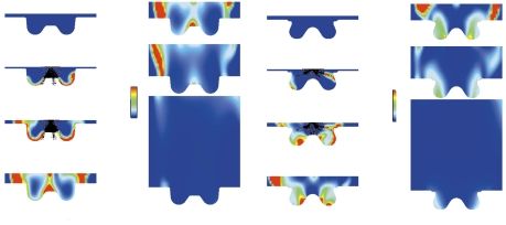
NADITM combustion chamber Conventional combustion chamber
Figure 3
Computed combustion process at 4000 rpm full load.B Walter and B. Gatellier / Near Zero NOx Emissions and High Fuel Efficiency Diesel Engine 107
2.2 Best Configuration actual European Diesel engines, a power of 45 kW/l1 was
achieved at 4000 rpm, full load:
CFD computations helped to define the best fuel injection – maximum in-cylinder pressure: 15 MPa;
and combustion process. Figure 3 shows the combustion
– exhaust temperature: 750°C (equivalent to 710°C on a
process at 4000 RPM, full load, with a conventional nozzle single-cylinder);
and combustion chamber geometry and with the NADITM
– smoke: < 3 FSN;
concept. The fuel air mixture is represented in a colour that
– intake pressure: 205 kPa;
depends on the lambda value: the fuel droplets in black, the
– exhaust pressure: 315 kPa;
fuel vapour in red, the air in blue. With conventional
combustion system, the fuel is injected towards the bowl – intake temperature: 60°C.
periphery. Due to fuel/wall interaction, the majority of the
fuel is sent to the centre of the bowl, mixes with air and 4.2 Comparison with NADITM Combustion System
burns. Some fuel mixes with air and burns in the squish area.
With the NADITM concept, the fuel is injected at the centre of The conventional combustion system and the first version of
the combustion piston bowl. Due to fuel/wall interaction, fuel the NADITM concept were compared on the same single-
is transported to the piston bowl periphery, mixes with air cylinder engine at 4000 rpm, full load. Figure 4 shows the
and burns. exhaust temperature and the smoke evolution during a fuel
injected quantity increase. NADITM combustion system
shows good conventional Diesel combustion behaviour,
3 NADITM ENGINE DESCRIPTION reaching almost the same power (only 1% less) with more
smoke, but still below the limit. This first engine evaluation
The experiments were performed on a single-cylinder engine. had confirmed the possibility to find a combustion chamber
The main characteristics are: adapted to narrow spray cone angle. Nevertheless, some
– bore: 78.3 mm; drawbacks were pointed out at this initial development stage.
We have observed an increase of the ignition delay and a
– stroke: 86.4 mm;
smaller reaction rate. So, these preliminary results have been
– displacement: 416 cm3; obtained with an advanced injection timing, with some
– compression ratio: 16:1. drawbacks on maximum in-cylinder pressure (+ 0.5 MPa),
The intake ducts have been modified in order to adapt the
swirl motion. All the results shown in this paper, including
full load conditions have been obtained with the same swirl
number. A first generation production Bosch common rail
825
fuel injection system (maximum injection pressure: 135 MPa)
has been modified in order to allow up to eight injections per 800
Conventional
cycle. The engine was externally boosted and the exhaust NADITM
775
pressure was controlled by a throttle valve in accordance
Exhaust temperature (°C)
45 kW/l
with intake pressure and EGR values. 750 44.5 kW/l
725
4 FULL LOAD TESTS 700
The first target was to validate the concept on a single 675
cylinder engine with conventional combustion mode at full
650
load.
625
4.1 Reference
600
0 1 2 3 4
For the concept development program, the first objective was Smoke (FSN)
to find the same performance, in terms of power, as for the
initial conventional combustion system. To have a fair Figure 4
comparison basis at full load, the original combustion piston First results at 4000 rpm, full load.
bowl was modified in order to reduce the compression ratio
to 16:1. With the next typical Diesel engine parameters (1) Calculated from IMEP, with a friction mean effective pressure
settings and limiting factors, which are used in most of the (FMEP) or 2 bar.108 Oil & Gas Science and Technology – Rev. IFP, Vol. 58 (2003), No. 1
on fuel consumption (+10%) and on combustion noise power density. Figure 6 shows the improvements: the intake
(+2 dB). As it will be discussed later, improvements have pressure has been increased up to 300 kPa at a constant
been done to avoid these drawbacks. maximum in-cylinder pressure of 16 MPa, and with less than
3 FSN for the smoke and 710°C for the exhaust temperature.
4.3 Improvment at Full Load
5 RESULTS IN HCCI MODE
After the first evaluation of the concept, the combustion
system has been improved to obtain better results at high
load, using conventional combustion mode. Then, this 5.1 Combustion Control
improved concept has been evaluated at part load using
HCCI combustion mode. As said in the Introduction, combustion control is the key
point in HCCI mode.
The future Diesel engine requirements in terms of power
density (up to 60 kW/l) will lead to higher intake pressure We have developed many ways to have a good control of
and in-cylinder pressure. In this context, it becomes obvious combustion, using EGR, the effective compression ratio, gas
temperature and injection timing.
that a too high sensitivity to injection timing could be a
critical point. The combustion bowl shape has been modified 5.1.1 EGR
in order to reduce the ignition delay and to improve the
combustion rate by promoting a better air/fuel mixing. As External EGR is the main way used to control the ignition of
seen for Figure 2, the “extraction” speed of the bowl was the combustion, with a given compression ratio. EGR rate is
increased by a reduction of the out-section and thanks to a defined as:
work on the total length of the bowl and on bowl dome
shape. CO 2intake(%) − CO 2air(%)
EGR(%) = 100 ×
Figure 5 shows the in-cylinder pressure and the burned CO 2 exhaust(%) − CO 2air(%)
fraction with the initial and optimised geometries with an
intake pressure of 260 kPa and maximum cylinder pressure As Figure 7 shows, air dilution by exhaust gas increases
of 15 MPa. The ignition delay is reduced by 3° CA and it is the ignition delay and allows good combustion timing
possible to achieve 6.3% more power in the same conditions. control. However, the increase of EGR decreases the air/fuel
With this improved design, the combustion behaviour is ratio and could, above a certain limit, increase the unburned
less sensitive to injection timing variations and it is possible fuel with a negative impact on fuel consumption: high EGR
to reach the future Diesel engine requirements in terms of rates are not totally compatible with high load, and in these
60 4000 rpm, full load
18
Optimised geometry 125
16 - 3° CA auto ignition delay Initial
+ 6.3% Power
14 Improved
Cylinder pressure (MPa)
120
Burned fraction (mm3)
12 40
10 115
Power (%)
Initial geometry
8
6 20 110
4
105
2
0 0
320 360 400 440 480 100
Crank angle (CA) 200 220 240 260 280 300
Intake pressure (kPa)
Figure 6
Figure 5
Engine power output versus intake pressure (in-cylinder
Comparison between initial and optimised geometries. pressure < 16 MPa).B Walter and B. Gatellier / Near Zero NOx Emissions and High Fuel Efficiency Diesel Engine 109
100 110
Valve closing timing variation
Geometric CR variation
75 CR 12:1 CR 14:1
45% CR 16:1
Burned fraction (%)
60% 100
Air flow (%)
-30 CA
50 65%
Effective CR 14:1 +20 CA
Increase of EGR rate 90
25
-50 CA
+30 CA
+40 CA
0 80
330 360 390 420 760 780 800 820
Cranck angle (CA) Temperature before combustion (°C)
Figure 8
Figure 7
Influence of valve closing timing on effective compression
Influence of EGR on combustion timing. ratio.
0.10 7
Inlet gas 75°C
Inlet gas 105°C 6
0.08
Cylinder pressure (MPa)
Heat of release ( 1/°CA )
5
0.06
4
3
0.04
2
Optimised injection
0.02 timing
1
0 0
320 340 360 380 400 320 340 360 380 400
Crank angle (CA) Crank angle (CA)
Figure 9 Figure 10
Effect of intake gas temperature on the combustion. Effect of injection timing.
cases, a decrease of the effective compression ratio is As shown in Figure 8, an earlier valve closing of 30° CA or a
necessary to have the same ignition timing with a smaller later valve closing of 20° CA gives the same ignition
EGR rate. characteristics as a geometric compression ratio of 14:1 with
a small loss of airflow.
5.1.2 Compression Ratio Combined with high EGR rate, the decrease of the
At this initial stage, two geometric compression ratios (16:1 effective compression ratio allows to increase the maximum
and 14:1) have been used to easily evaluate its effect on load.
combustion ignition. In the meantime, 1D calculations have
5.1.3 Intake Gas Temperature
shown that it is possible to adjust pressure and temperature
evolution against crank angle by varying the intake valve Another parameter to control the combustion timing is the
closing at constant geometric compression ratio of 16:1. intake gas temperature: the higher the temperature, the110 Oil & Gas Science and Technology – Rev. IFP, Vol. 58 (2003), No. 1
sooner the ignition. To control this temperature, EGR cooling light boost pressure has been used above 0.5 MPa of IMEP
is necessary, especially with high EGR rates. Nonetheless, with the lowest compression ratio.
EGR does not have to be too cooled as problems of
Operating Range and ISFC (Fig. 11).
condensation of unburned hydrocarbons appear with a
temperature below 70°C. Figure 9 shows the impact of a With the geometric compression ratio of 16:1, it is possible
decrease of the intake gas temperature (mix of air and EGR to achieve 0.4 MPa of IMEP using HCCI mode. The fuel
in intake manifold) on the combustion ignition timing. Note consumption increase is due to the unburned fuel at the
that there is an effect on the low temperature oxidation phase exhaust (HC and CO), which could represent 10% of the
as well as on the main combustion. injected fuel at 0.4 MPa. With the geometric compression
ratio of 14:1, it is possible to achieve 0.6 MPa of IMEP using
5.1.4 Injection Timing HCCI mode. The fuel consumption is better because less
EGR is needed to control the combustion timing well with a
A fourth way to control the ignition timing is linked to the net benefit on the unburned fuel which represents only 2% of
injection strategy. As shown in Figure 10, injection timing the injected fuel quantity at 0.5 MPa of IMEP.
could be optimised in order to change fuel stratification and
to interact with auto-ignition sites. Emissions
For NOx and particulate emissions, as Figure 12 shows, the
levels are near zero (always below 0.03 g/kWh) and
5.2 Engine Results
consistent with SULEV standard levels. NOx emissions are
Two engine speeds have been selected to perform our first more than 100 times lower than conventional Diesel engine
HCCI mode engine evaluation (1500 rpm and 2500 rpm). and particulate emissions are more than 10 times lower. The
The results obtained in HCCI mode with the NADITM HC and CO emissions are not too high with levels in the
concept geometry are compared to results with conventional same range or lower than direct gasoline engine ones (see
combustion mode with standard geometry using a Fig. 13). However, as the exhaust temperature is low,
compression ratio of 18:1, and parameters settings consistent especially at low load, improvements of oxidation catalyst
with Euro III emissions standards. performances will be required.
5.2.1 Results at 1500 rpm 5.2.2 Results at 2500 rpm
The Figures 11 to 13 show fuel consumption and pollutant Figures 14 to 16 show fuel consumption and pollutant
emissions versus engine load. The boost- and back-pressures emissions against engine load. At high load, the EGR flow
used for these tests were very close from values used on the has been cooled to maintain the recycled gas temperature at
production engines. Indeed, for the 1500 rpm tests, only a about 90°C. The intake pressure has been progressively
280 0.07 0.07
270 Reference (18:1) 16:1 (NOx)
0.06 14:1 (NOx) 0.06
260 HCCI (16:1)
HCCI (14:1) 16:1 (particulate)
250 0.05 0.05
14:1 (particulate)
Particulate (g/kWh)
ISFC (g/kWh)
NOx (g/kWh)
240
0.04 0.04
230
0.03 0.03
220
210 0.02 0.02
200
0.01 0.01
190
180 0.00 0.00
0 0.2 0.4 0.6 0.8 1.0 1.2 0 0.2 0.4 0.6
IMEP (MPa) IMEP (MPa)
Figure 11 Figure 12
ISFC vs IMEP at 1500 rpm. Emissions vs engine load at 1500 rpm.B Walter and B. Gatellier / Near Zero NOx Emissions and High Fuel Efficiency Diesel Engine 111
70 14 280
16:1 (CO)
270 Reference (18:1)
60 14:1 (CO) 12
16:1 (HC) 260 HCCI (16:1)
14:1 (HC) 10 HCCI (14:1)
50 250
ISFC (g/kWh)
CO (g/kWh)
HC (g/kWh)
40 8 240
230
30 6
220
20 4 210
200
10 2
190
0 0 180
0 0.2 0.4 0.6 0 0.2 0.4 0.6 0.8 1.0 1.2
IMEP (MPa) IMEP (MPa)
Figure 13 Figure 14
Emissions vs engine load at 1500 rpm. ISFC vs IMEP at 2500 rpm.
0.07 0.07 70 14
16:1 (CO)
16:1 (NOx)
0.06 0.06 60 14:1 (CO) 12
14:1 (NOx)
16:1 (HC)
16:1 (particulate) 14:1 (HC)
0.05 0.05 50 10
14:1 (particulate)
Particulate (g/kWh)
CO (g/kWh)
HC (g/kWh)
NOx (g/kWh)
40 8
0.04 0.04
0.03 0.03 30 6
0.02 0.02 20 4
10 2
0.01 0.01
0.00 0.00 0 0
0 0.2 0.4 0.6 0.8 1.0 0 0.2 0.4 0.6 0.8 1.0
IMEP (MPa) IMEP (MPa)
Figure 15 Figure 16
Emissions vs engine load at 2500 rpm. Emissions vs engine load at 2500 rpm.
increased for IMEP higher than 0.5 MPa, but remains lower Emissions
than conventional value in order to take into account the Once again, near zero NOx and particulate emissions are
fewer energy available on the turbine, due to HCCI achieved as shown in Figure 15.
combustion mode. The HC and CO emissions are in the same range as direct
gasoline engine ones (Fig. 16). At this engine speed, the
Operating Range and ISFC (Fig. 14)
exhaust temperature is high enough to oxidise more easily
Due to higher engine speed, it is possible to achieve good the HC and CO by a catalyst. Depending on engine
HCCI combustion mode at higher load. It is possible to parameters settings such as EGR or injection timings, it is
achieve 0.6 MPa of IMEP with a compression ratio of 16:1, possible to find different trade-off between the four
and 0.9 MPa of IMEP with a compression ratio of 14:1 using pollutants. The results shown with the lowest compression
HCCI mode. ratio illustrate this point.112 Oil & Gas Science and Technology – Rev. IFP, Vol. 58 (2003), No. 1
6 PERSPECTIVES – transition strategies between the two modes have to be
defined, with a special attention to EGR control;
The NADITM concept has already achieved interesting – HCCI engine load domain has to be extended a little.
results. 50 kW/l has been reached with conventional limiting Nevertheless, the use of advanced engine technologies
factors and engine parameters setting (in-cylinder pressure such as VVA, low temperature oxidation catalysts light off,
below 15 MPa, exhaust temperature below 750°C, smoke electric assisted turbocharger or further generation of common
less than 3, intake pressure of 230 kPa). In order to fulfill the rail fuel injection system make practical applications
future DI engine standard, directions of progress are of NADITM engine realistic in near future production
identified. powertrains
To improve the conventional combustion mode, the
increase of injection pressure (from 135 MPa to 160 MPa or
higher) will promote the air/fuel mixing. The nozzle ACKNOWLEDGEMENTS
configuration (number and diameter of the holes) could be
optimised by taking into account the completely different The authors would like to express their acknowledgements to
trade-off between pollutant emissions at low and medium Pascal Gréau for diligently running the engine experiments,
load and power at full load. Marjorie Miche and Stéphane Henriot for the 3D calculation,
To improve the HCCI combustion mode, the control Jean-Charles Dabadie for the 1D calculation.
parameters settings such as the split of injection, the EGR or
the boost pressure has to be deeply optimised. The impact of
new technologies suchlike as piezzo-electric common rail REFERENCES
FIS to increase the injection events, electric assisted turbo 1 Najt, P.M. and Foster, D.E. (1983) Compression – Ignited
charger to enlarge the operating range or, for advanced Homogeneous Charge Combustion. SAE Paper 830264.
development, fully VVA system, has to be precised. 2 Thring, R.H. (1989) Homogeneous – Charge Compression –
Due to the complexity of the processes involved, IFP has Ignition (HCCI) Engines. SAE Paper 892068.
already planned to use sophisticated scientific tools, such as 3 Ryan, T.W. and Callahan, T.J. (1996) Homogeneous Charge
optical access engines and associated diagnostics and 3D Compression Ignition of Diesel Fuel. SAE Paper 961160.
CFD tools, to acquire the necessary knowledge to support the 4 Gray, A.W. and Ryan, T.W. (1997) Homogeneous Charge
Compression Ignition (HCCI) of Diesel Fuel. SAE Paper
NADITM concept development process to the industrial 971676.
application. 5 Christensen, M., Johansson, B. and Einewall, P. (1997)
Homogeneous Charge Compression Ignition (HCCI) Using
Isooctane, Ethanol and Natural Gas – A Comparison with
CONCLUSION Spark Ignition Operation. SAE Paper 972874.
6 Christensen, M., Johansson, B., Amnéus, P. and Mauss, F.
This paper has presented the main design features and (1998) Supercharged Homogeneous Charge Compression
preliminary results of the NADITM new combustion system Ignition. SAE Paper 980787.
applied to an existing DI Diesel engine. It was shown that 7 Christensen, M. and Johansson, B. (1998) Influence of
Mixture Quality on Homogeneous Charge Compression
this concept could be an answer to the Diesel engine Ignition. SAE Paper 982454.
challenges. This “dual mode” engine has reached near zero
8 Christensen, M. and Johansson, B. (1999) Homogeneous
NOx and particulate emissions at part load (including MVEG Charge Compression Ignition with Water Injection. SAE
operating range) by using some homogeneous charge Paper 1999-01-0182.
compression ignition combustion and is compatible with 9 Richter, M., Franke, A., Aldén, M., Hultqvist, A. and
further specifications concerning power density. In the HCCI Johansson, B. (1999) Optical Diagnostics Applied to a
Naturally Aspired Homogeneous Charge Compression
mode, a lot of development studies have been done on the Ignition Engine. SAE Paper 1999-01-3649.
control of combustion with the use of:
10 Christensen, M., Hultqvist, A. and Johansson, B. (1999)
– high EGR rate; Demonstrating the Multi Fuel Capability of a Homogeneous
– variable effective compression ratio thanks to valve timing Charge Compression Ignition Engine with Variable
Compression Ratio. SAE Paper 1999-01-3679.
variations;
11 Hultqvist, A., Christensen, M., Johansson, B., Franke, A.,
– intake gas temperature (cooled EGR); Richter, M. and Aldén, M. (1999) A Study of Homogeneous
– injection timing. Charge Compression Ignition Combustion Process by
Some points have to be improved and further develop- Chemiluminescence Imaging. SAE Paper 1999-01-3680.
ment works are already planned: 12 Christensen, M. and Johansson, B. (2000) Supercharged
Homogeneous Charge Compression Ignition (HCCI) with
– CO and HC emissions have to be improved, especially at Exhaust Gas Recirculation and Pilot Fuel. SAE Paper 2000-
low engine speed and engine load; 01-1835.B Walter and B. Gatellier / Near Zero NOx Emissions and High Fuel Efficiency Diesel Engine 113
13 Amano, T., Morimoto, S. and Kawabata, Y. (2001) Modeling 27 Shimazaki, N., Akagawa, H. and Tsujimura, K. (1999) An
of the Effect of Air/Fuel Ratio and Temperature Distribution Experimental Study of Premixed Lean Diesel Combustion.
on HCCI Engines. SAE Paper 2001-01-1024. SAE Paper 1999-01-0181.
14 Olsson, J.O., Tunestal, P. and Johansson, B. (2001) Closed – 28 Akagawa, H., Miyamoto, T., Harada, A., Sasaki, S.,
Loop Control of an HCCI Engine. SAE Paper 2001-01-1031. Shimazaki, N., Hashizume, T. and Tsujimura, K. (1999)
15 Hultqvist, A., Engdar, U., Johansson, B. and Klingmann, J. Approaches to Solve Problems of the Premixed Lean Diesel
(2001) Reacting Boundary Layers in a Homogeneous Charge Combustion. SAE Paper 1999-01-0183.
Compression Ignition (HCCI) Engine. SAE Paper 2001-01- 29 Hayashi, A. K., Miyamoto, T., Harada, A., Sasaki, S.,
1032. Akagawa, H. and Tsujimura, K. (1999) A Computational
16 Yokota, H., Kudo, Y., Nakajima, H., Kakegawa, T. and Investigation of Premixed Lean Diesel Combustion. SAE
Suzuki, T. (1997) A New Concept for Low Emission Diesel Paper 1999-01-0229.
Combustion. SAE Paper 970891. 30 Kimura, S., Matsui, Y. and Koike, M. (1998) New
17 Yokota, H., Nakajima, H. and Kakegawa, T. (1998) A New Combustion Concept For Simultaneous Reduction of NOx
Concept for Low Emission Diesel Combustion (2nd Rep.: and Particulate Emissions From Small DI Diesel Engines.
Reduction of HC and CO Emission, and Improvement of 1998 FISITA World Automotive Congress, Paris, France,
Fuel Consumption by EGR and MTBE Blended Fuel). SAE September 27 - October 1.
Paper 981933. 31 Mase, Y. and Kawashima, J. I. (1998) Nissan’s New 4V
18 Yanagihara, H., Sato, Y. and Mizuta, J. (1996) A HSDI – Diesel Engine with MK Concept. 19th. International
Simultaneous Reduction of NOx and Soot in Diesel Engines Vienna Motor Symposium, Vienna, Austria, May 7-8.
under a New Combustion System (Uniform Bulky 32 Mase, Y., Kawashima, J.I. and Sato, T. (1998) Nissan New
Combustion System – UNIBUS). 17th. International Vienna Multivalve DI Diesel Engine Series. SAE Paper 981039.
Motor Symposium, Vienna, Austria, April, 25-26.
33 Kimura, S., Aoki, O., Ogawa, H. and Muranaka, S. (1999)
19 Kato, S. (1998) Toyota’s Approach to Environmental New Combustion Concept for Ultra-Clean and High-
Protection toward the 21 st Century. 19 th . International Efficiency Small DI Diesel Engines. SAE Paper 1999-01-
Vienna Motor Symposium, Vienna, Austria, May 7-8. 3681.
20 Yanagihara, H., Sato, Y., Ohoki, H., Takahashi, K., 34 Kimura, S., Aoki, O., Kitahara, Y. and Aiyoshizawa, E.
Nakahara, S., Mizuta, J. and Sakamoto, H. (1998) A Study of (2001) Ultra – Clean Combustion Technology Combining a
DI Diesel Engine Combustion under Uniform and Highly Low – Temperature and Premixed Combustion Concept for
Dispersed Mixture Formation – Possibility of Ignition Meeting Future Emission Standards. SAE Paper 2001-01-
Timing Control. SAE Paper 9830956. 0200.
21 Iwabuchi, Y., Kawai, K., Shoji, T. and Takeda, Y. (1999) Trial 35 Suzuki, H., Koike, N. and Odaka, M. (1997) Exhaust
of New Concept Diesel Combustion System – Premixed Purification of Diesel Engines by Homogeneous Charge with
Compression – Ignited Combustion. SAE Paper 1999-01-0185. Compression Ignition, Part 1: Experimental Investigation of
22 Takeda, Y., Ishikawa, N., Komori, M. and Tsujimura, K. Combustion and Exhaust Emission Behavior Under Pre-
(1994) Diesel Combustion Improvement and Emissions Mixed Homogeneous Charge Compression Ignition Method.
Reduction Using VCO Nozzles with High Pressure Fuel SAE Paper 970313.
Injection. SAE Paper 940899. 36 Suzuki, H., Koike, N. and Odaka, M. (1997) Exhaust
23 Takeda, Y. and Niimura, K. (1995) Characteristics of Diesel Purification of Diesel Engines by Homogeneous Charge with
Combustion and Emissions with a Multi-Injector System. Compression Ignition, Part 2: Analysis of Combustion
SAE Paper 952511. Phenomena and NOx Formation by Numerical Simulation
with Experiment. SAE Paper 970315.
24 Takeda, Y., Keiichi, Na. and Keiichi, Ni. (1996) Emission
Characteristics of Premixed Lean Diesel Combustion with 37 Suzuki, H., Koike, N. and Odaka, M. (1998) Combustion
Extremely Early Staged Fuel Injection. SAE Paper 961163. Control Method of Homogeneous Charge Diesel Engines.
SAE Paper 980509.
25 Hashizume, T., Miyamoto, T., Akagawa, H. and Tsujimura,
K. (1998) Combustion and Emission Characteristics of 38 Odaka, M., Suzuki, H., Koike, N. and Ishii, H. (1999) Search
Multiple Stage Diesel Combustion. SAE Paper 980505. for Optimizing Method of Homogeneous Charge Diesel
Combustion. SAE Paper 1999-01-0184.
26 Harada, A., Shimazaki, N., Sasaki, S., Miyamoto, T.,
Akagawa, H. and Tsujimura, K. (1998) The Effects of
Mixture Formation on Premixed Lean Diesel Combustion
Engine. SAE Paper 980533. Final manuscript received in November 2002114 Oil & Gas Science and Technology – Rev. IFP, Vol. 58 (2003), No. 1
APPENDIX The calculations presented here use the following models
to describe the physical processes occurring within the
The KMB code, which stands for Kiva-Multi-Block, is based combustion chamber: a standard κ−ε model for turbulence, a
on the KIVA-II code originally from Los Alamos Laboratory classical logarithmic law of the wall, two models for Diesel
[A1]. It makes possible computation of fully 3 dimensional, combustion (a kinetic combustion model for self-ignition
transient, compressible, chemically reactive, turbulent flows developed at IFP [A4] and the Magnussen model [A5] for
in moving geometries, with sprays. The formulation of the turbulent combustion), and the Diwaker model [A6] for heat
equations, the averaged Navier-Stokes’ equations coupled transfer.
with turbulence equations, is an arbitrary Lagrangian
Eulerian finite volume formulation, resolved on hexahedrons A1 Amsden, A. A., O’Rourke, J., Butler, T. D. (1989) KIVA-II:
in structured domains. a Computer Program for Chemically Reactive Flows with
Sprays. Los Alamos LA-11560-MS (Technical Report).
A multi-block version developed at IFP [A2], allows
computation in complex geometries. Each part of a A2 Habchi, C., Torres, A. (1992) A 3D Multi-Block Structured
Version of the KIVA 2 Code. First European CFD
geometry, for example the cylinder and the intake port, can Conference, Bruxelles, Belgium, September 1992.
be meshed and logically structured independently. Some A3 Torres, A., Henriot, S. (1994) 3D Modeling of Combustion in
overlap allows physical data to be transmitted from one block Lean Burn Four Valves Engines: Influence of Intake
to the other. This method drastically reduces the number of Configuration”, 3th International Symposium on Diagnostics
and Modeling of Combustion in Internal Combustion
ghost cells with respect to a single block containing all the Engines, (COMODIA), Yokoama, Japan, July 1994.
geometry.
A4 Chalak, Z. (1990) Modélisation du délai d’auto-inflammation
A remapping algorithm is also used at valve closing, to dans un moteur Diesel ; Validation expérimentale. PhD
transfer all the computed fields from a grid with valve used Thesis, université de Rouen.
for intake phase, to a grid without valve used for A5 Magnussen, B. F., Hjertager, B. H. (1976) On Mathematical
compression and combustion phases. This avoids very thin Modeling of Turbulent Combustion with Special Emphasis
on Soot Formation and Combustion. 16 th Symposium on
and distorted cells near the engine head during these two last Combustion, Pittsburg, USA, 1976.
phases. This more homogeneous grid allows larger time steps
A6 Diwakar, R. (1984) Assessment of the Ability of a
and better accuracy during injection and combustion. These Multidimensional Computer Code to Model Combustion in a
abilities are described in [A3]. Homogeneous Charge Engine. SAE Paper 840230.You can also read