AUTOMOTIVE BATTERIES 101 - JULY 2018 WMG, University of Warwick Professor David Greenwood, Advanced Propulsion Systems
←
→
Page content transcription
If your browser does not render page correctly, please read the page content below
AUTOMOTIVE BATTERIES 101

JULY 2018
WMG, University of Warwick
Professor David Greenwood, Advanced Propulsion Systems
The battery is the defining
      component of an
      electrified vehicle
                                       Cost   Power
             Range

             Package
                                                 Life

                         Ride and Handling

    © 2018
2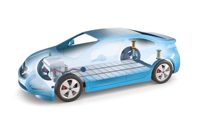
Primary functions of
the battery across
vehicle types

                   ENGINE           MOTOR                 ‘BATTERY’          BATTERY FUNCTION

CONVENTIONAL       100kW            Starter motor         12V                Engine starting
(ICE)              Full transient   Stop/start            3kW, 1kWh          (3kW, 2-5Wh) Ancillary
                                                                             loads (400W average,
                                                                             4kW peak, ~1kWh)

                                                                                                      Increasing power to energy ratio
MILD HYBRID        90-100kW         3-13kW                12-48V             Absorb regenerated
(MHEV)             Full transient   Torque boost/re-gen   5-15kW, 1kWh       braking energy

FULL HYBRID        60-80kW          20-40kW               100-300V           Support acceleration
(HEV)              Less transient   Limited EV mode       20-40kW, 2kWh

PLUG-IN HYBRID     40-60kW          40-60kW               300-600V           Provide primary power
(PHEV)             Less transient   Stronger EV mode      40-60kW, 5-20kWh   and energy

RANGE-EXTENDED     30-50kW          100kW                 300-600V           Provide primary power
(REEV)             No transient     Full EV mode          100kW, 10-30kWh    and energy

ELECTRIC VEHICLE   No Engine        100kW                 300-600V           Provide sole power
(EV)                                Full EV mode          100kW, 30-80kWh    and energy source

                                                                                          © 2018

                                                                                                                                         3
Biggest challenge for
      mass market uptake is cost
      COMPONENT COSTS FOR ELECTRIFICATION OF POWERTRAIN

                                                                                      BATTERY
    Conventional
                                                                                      COST IS
                                                                                      THE SINGLE
             MHEV                                                                     BIGGEST
                                                                                      FACTOR
              HEV                                                                     Engine/Transmission
                                                                                      Battery
                                                                                      Power Electronics
                                                                                      Motor
             PHEV
                                                                                      Charger
                                                                                      E-ancillaries

               EV

                    0   2000     4000           6000           8000   10000   12000

                                Bill-of-Materials Component Cost €

    © 2018
4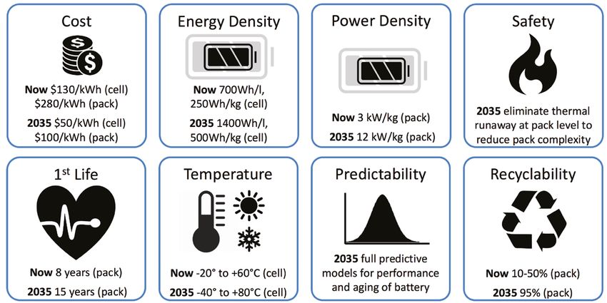
Lithium-ion batteries are
     improving rapidly                                                                                                   18650 CELL CAPACITY (MAH)

     •
       Costs have fallen dramatically due to technology,
       production volume and market dynamics
                                                                                                            4000
     •
       Pack cost fallen from $1,000/kWh to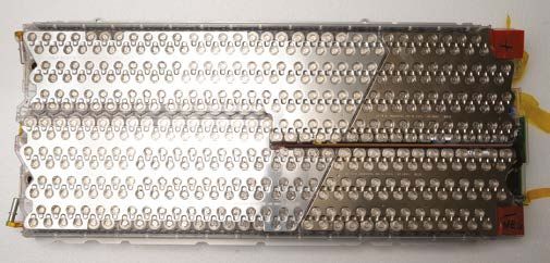
What makes up an
      automotive battery?

      Lithium-ion cell                           Module                                      Pack

      e.g. pouch or cylindrical cell             e.g. module for pouch cells (Nissan Leaf)   e.g. pack for pouch cells (Nissan Leaf)

      As a single unit, a ‘cell’ performs the    A ‘module’ is formed by connecting          A ‘pack’ is formed by connecting
      primary functions of a rechargeable        multiple ‘cells’, providing them with       multiple ‘modules’ with sensors
      ‘battery’. Cells come in varied formats:   a mechanical support structure and          and a controller and then
                                                 thermal interface and attaching             housing the unit in a case.
      • Cylindrical Cells
                                                 terminals. Modules are designed             Electric vehicles are equipped
      •
        Pouch Cells                              according to cell format, target pack       with batteries in a ‘pack’ state
                                                 voltage and vehicle requirements.           which are connected to
      •	Prismatic Cells                                                                     the powertrain.

    © 2018
6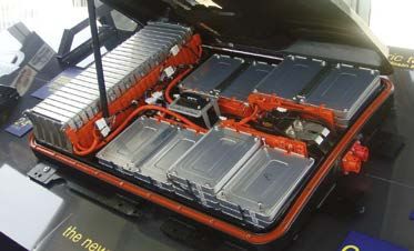
How a Lithium-ion
Charging
cell works NiO6
Li+
e-
e-
Li+
Charge
Cathode
Anode
•
Lithium-ion (Li-ion) is a negative electrode to the
Discharge
general term for a variety of positive through the outer
Li+ e-
batteries whose properties circuit (the power supply).
rely on lithium as the When no more lithium-ions Li e- Li+
charge carrier. Li-ion offers will flow, the battery is
Cathode Material Anode Material
advantages over other fully charged e.g. LiCoO2 e.g. graphite
chemistries such as weight
•
During discharge, the
and voltage. For automotive
lithium-ions flow back
purposes, rechargeable Anode/cathode materials: specific capacities and
through the electrolyte/
cells are used operating voltages vs pure lithium
separator to the cathode.
•
There are many types of Electrons flow back to the Different chemistries suit specific requirements
Li-ion battery depending anode through the outer
on the exact combination circuit. When all ions have 5 LiMn1.5Ni0.5O4
ENERGY DENSITY
of materials used for the moved back, the battery is 4.5
LiMn2O4 LiMn1/3Co1/3Ni1/3O2
4 Cathode
anode and cathode fully discharged and needs LiNiO2
recharging 3.5 LiCoO2
Anode
Voltage vs Li(V)
•
During charging, the 3 LiFePO4
2.8V
3.5V
positively charged lithium- •
A motor converts the 2.5
3.7V
Li2FeS2
ions flow from the cathode, electrical energy from the 2 3.2V
LTO
through the electrolyte/ battery into mechanical 1.5
2.0V
TiO2-B
separator, to the anode energy to turn the wheels 1
Hard Carbons
Metal Nitrides
where they are stored. 3.8V
Silicon
•
Electricity from the grid is Graphite Lithium
Electrons flow from the 0
M alloys
used to charge the battery 0 200 400 600 3500 4200
141 mAh/g
Specific Capacity (mAh/g)
3.7 V x 141 Ah/kg = 512 Wh/kg
© 2018
7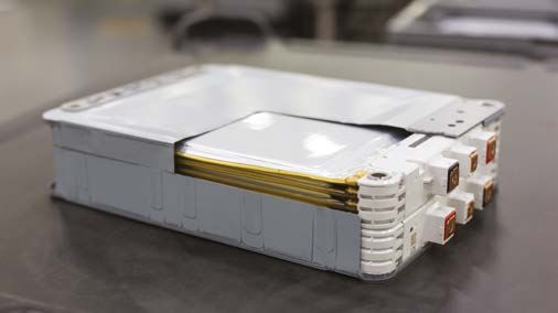
Current lithium-ion
            battery chemistries:
              CATHODE/ANODE MATERIAL            STRENGTHS                                         WEAKNESSES

              Lithium Cobalt Oxide              •
                                                  High energy                                     •
                                                                                                    Thermally unstable
              (LCO) Cathode                     • High power                                      •
                                                                                                    Relatively short life span
                                                                                                  •
                                                                                                    Limited load capabilities
              Lithium Manganese Oxide Spinel    •
                                                  High power and thermal stability                •
                                                                                                    Low capacity compared to other cathode materials
              (LMO) Cathode                     • Enhanced safety                                 • Limited life cycle
                                                • Low cost                                        •
                                                                                                    Need advanced thermal management
              Lithium Nickel Cobalt Aluminium   •
                                                  High specific energy                            •
                                                                                                    Safety issues
Cathode

              Oxide (NCA) Cathode               •
                                                  Good specific power                             • Cost
                                                •
                                                  Long life cycle
              Lithium Nickel Manganese Cobalt   •
                                                  Ni has high specific energy; Mn adds low        •
                                                                                                    Nickel has low stability
              Oxide (NMC) Cathode                 internal resistance                             •
                                                                                                    Manganese offers low specific energy
                                                •
                                                  Can be tailored to offer high specific energy
                                                  or power
              Lithium Iron Phosphate            •
                                                  Inherently safe; tolerant to abuse              •
                                                                                                    Lower energy density due to low operating
              (LFP) Cathode                     •
                                                  Acceptable thermal stability                      voltage and capacity
                                                •
                                                  High current rating
                                                •
                                                  Long cycle life
              Graphite/Carbon-based             •
                                                  Good mechanical stability                       •
                                                                                                    Low volumetric capacity
              Anode                             •
                                                  Good conductivity and Li-ion transport
                                                • Good gravimetric capacity

              Lithium Titanate                  •
                                                  Withstands fast charge/discharge rates          •
                                                                                                    Lower energy density compared to
Anode

              (LTO) Anode                       • Inherently safe                                   graphitic anodes
                                                • Long cycle life                                 • Cost

              Silicon Alloy                     •
                                                  High gravimetric/volumetric capacity            •
                                                                                                    High degree of mechanical expansion
              (Si) Anode                        • Low cost                                          on charging
                                                • Chemical stability

          © 2018
8
Promising battery chemistries:
early stage research
 CHEMISTRY*                      PROPERTIES/BENEFITS                                              RESEARCH CHALLENGES

 Solid State Batteries           •
                                   Solid electrolyte and separator components; no concerns over   •
                                                                                                    Improving poor conductivity
                                   ‘leakage’                                                      •
                                                                                                    High volume manufacturing at
                                 •
                                   Improved safety due to lack of liquid electrolyte                acceptable cost
                                 •
                                   High operating voltages increase potential
                                   energy density
                                 •
                                   Lighter and more space efficient; less need for cooling

 Metal Air Batteries             •
                                   Pure metal anode and ambient air/O2 cathode                    •
                                                                                                    Short life cycle
 e.g. Li, Al, Zn, Na             • Very high theoretical capacity                                 • Issues with practical rechargeability
                                 • Increased safety vs Li-ion                                     • Air handling
                                 • No use of heavy metals                                         • Energy density reduces at high power

 Lithium Sulphur                 •
                                   High theoretical gravimetric energy density                    •
                                                                                                    Poor volumetric energy density
 (Li-S)                          •
                                   Sulphur is a low cost, abundant material                       •
                                                                                                    Issues with power density and
                                 •
                                   Improved safety                                                  discharge rate
                                                                                                  • Issues with cycle life stability

 Sodium-ion                      •
                                   Sodium is a low cost, abundant material                        •
                                                                                                    Issues of volumetric/gravimetric energy
 (Na-ion)                        •
                                   Improved safety for battery transportation                       density compared to Li-ion

 Silicon-based Electrodes        •
                                   Si has ~x10 gravimetric capacity compared to graphite          •
                                                                                                    Does not offer long cycle life
 (Si)                            •
                                   Could be lighter and/or store more energy                      •
                                                                                                    Practical application constraints

*Promising chemistries included are those demonstrating suitable
  application potential for automotive requirements at lab scale.

                                                                                                                                 © 2018

                                                                                                                                              9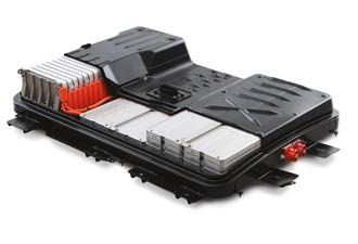
Automotive battery:
       cell components                                                                                      +ve/-ve Terminals

                                                                                                                                Electrolyte

       Active electrodes: Thinly wound or stacked into alternating sheets of material
       following a pattern: cathode – separator – anode.
       Quality and purity of material has an impact on charge efficiency and battery life.
       • C
          athode: Positively charged electrode in the battery cell, often made of a
         lithium metal oxide and coated on to a current collecting aluminium (Al) foil.
                                                                                             Metallised
       • Anode: Negatively charged electrode in the battery cell, often made of             foil pouch
          graphite and coated on to a current collecting copper (Cu) foil.                                Anode
       • Terminals: positive and negative contacts to connect the cells and module.                              Separator     Cathode

         Separator: Thin layer of polymer electrically isolates the cathode and anode
       •
         from one another to prevent short circuit. Its structure allows lithium ions to
                                                                                                  +ve/-ve                       Electrolyte
         pass through, allowing current to flow through the cell (microporosity)
                                                                                                  Terminals
         Electrolyte: A liquid transport medium which surrounds the electrodes and
       •
         soaks into the separator, allowing lithium ions to flow freely
         Additives: Electrode and electrolyte properties can be improved by adding
       •
         small amounts of other components, e.g. conductive additives
                                                                                                Metal
       • C
          urrent Interrupt Device: A pressure valve disables the cell in case of
                                                                                                case
         over-charge/over-heating
                                                                                                   Anode
                                                                                                              Separator    Cathode

     © 2018
10
Production steps for electrode/
cell manufacturing
Powder Mixing Coating Drying Calendering Slitting
Electrode manufacturing
Cell stacking Tab welding Packaging Electrolyte Filling Formation/ageing EoL Testing
Cell assembly/electrical formation
© 2018
11Cell formats
Cylindrical cells Pouch cells Prismatic cells
• Highly developed • H
ighest power and energy • B
enefits lie part-way between
density at cell level cylindrical and pouch cells
• Standard sizes
• N
eeds volume for • L
ayered approach improves
• U
sed widely in consumer
commercialisation space utilisation
goods (well standardised)
• R
elatively lightweight and easy to • A
llows highly flexible module
• Mechanically self-supporting
package for effective use of space design for differing requirements
• H
igh volumes and price
competitive market
Challenges: Challenges:
• Little standardisation of format (VDA) • L
ittle standardisation of format
Challenges: (VDA)
•
Requires supporting structure within
• Relatively heavy a module • Can be expensive to manufacture
•
Shape reduces packaging • Some cooling constraints •
Large format cells contain high
density energy (safety issues if damaged)
• L
arge format cells contain high
energy (safety issues if damaged)
Image credit: Panasonic
© 2018
12Cell supply chain: materials content
Breakdown by relative weight and cost of cell materials shows the value is spread across components,
not just from the primary electrochemical materials.
TYPICAL MATERIAL VOLUME (CYLINDRICAL CELL) MATERIAL COMPONENT COST BREAKDOWN
(CYLINDRICAL CELL)
Cathode
Electrolyte 12% Material Electrolyte 9%
e.g. NCA 42%
Separator 2% Separator 14%
Anode
Current
Collector
(Cu) 9% Anode Current
Collector (Cu)
Anode 5%
Binders Anode
1% Binders 1%
Anode Material
Cathode e.g. graphite 29%
Binder 0%
Cathode Conductors 1%
Cathode Current Cathode Material
Anode Material Cathode Current Collector Collector (Al) 1% e.g. NCA 53%
e.g. graphite 29% (Al) 4%
Cathode Binder 0% Cathode Conductors 0%
Cathode Material e.g. NCA Cathode Current Collector (Al) Anode Binders Separator Figures source:
Cathode Conductors Anode Material e.g. Graphite Anode Current Collector (Cu) Electrolyte ITRI, Taiwan
© 2018
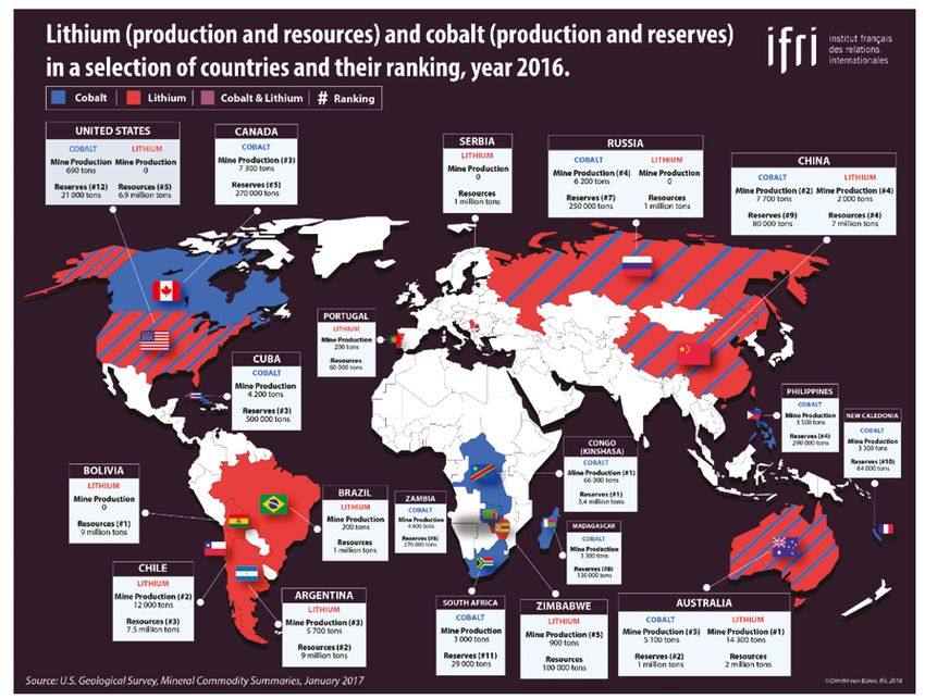
13Cell supply chain: materials sourcing
Image credit: Institut
francais des relations
internationales (ifri)
© 2018
146 1 2 Image credit:
Automotive battery: Nissan UK
module components
1 Casing: Metal casing provides mechanical
support to the cells and holds them under slight
compression for best performance
2 Clamping frame: Steel clamping frames secure the
modules to the battery case
3 Temperature sensors: Sensors in the modules 3
4 6 5
monitor the cell temperatures to allow the battery
management system to control cooling and power Pouch cell module (Nissan Leaf)
delivery within safe limits
4 ells: Each module in a pack contains the same
C 1 3 4 6 7
number of cells. The number of cells varies by
format and usage requirements
5 erminals: Two terminals on the module allow it to
T
be electrically connected to other modules via the
bus bars
6 Cell interconnects: Each cell has two tabs – one 5
positive and one negative. These are welded
together in series then connected to the terminals
7 Cooling channels: Liquid coolant runs between
rows of cells to withdraw heat and avoid thermal
runaway. Other packs, such as Nissan Leaf, instead
use air cooling
Cylindrical cell module (Tesla)
© 2018
15Module assembly - manufacturing process
MODULE ASSEMBLY LINE
Module BoL Cell Module Welding Contact Welding Module EoL
Test Insertion Welder Verification Welder Verification Test
Cell
Delivery Storage
Storage Module
Delivery
Handling
Assembly
Test
Primary tasks:
• Assembling the cells into a carrier •
Installing the module control unit with •
Testing the system
•
Joining the conductors in voltage and temperature sensors functionality
architecture (typically welded) •
Inserting cooling system components Lower cost achieved through
if required increased automation.
© 2018
16Automotive battery:
pack components
3 4
1
2
1 Upper case: Provides fire protection 5 Fusing: Fuses protect expensive
and watertight casing for the components from damage due to
battery components and protects power surges and faults
it from dirt ingress. Also shields
6 Disconnect: Used to electrically
service personnel from high voltage
isolate the battery from the vehicle
components
during servicing or maintenance
2 Battery modules: A ‘module’ is
7 Cooling: Modules require
formed by connecting multiple
cooling. Packs may be cooled
‘cells’, supporting those cells in
using air, water or vehicle air
a structural frame and then
conditioning system
attaching terminals. Modules are
designed according to cell format 8 Battery management system
and vehicle requirements (BMS): The BMS ensures the cells
remain within their safe operating
3 Bus bars: Electrically connect
temperatures and voltages. It
the battery modules together,
measures the remaining charge 9 8 7 6 5
and connect the modules to
in the battery and reports on
the contactors
state of health. It also ensures
4 Contactors: Electrically isolate the battery is correctly connected
the battery pack from the vehicle. and isolated before closing
Closed upon completion of safety the contactors
tests and opened in the event of a
9 Lower case: Structural casing
crash or battery fault
supports the mass of the battery
pack and protects it from damage
Image credits: Nissan UK
© 2018
17Battery management
system (BMS)
ells need to be monitored and
C
controlled, e.g. temperature, voltage.
The BMS is an electronic system that
manages cells in a battery pack.
key off: store data
key on: initialize
• The BMS monitors and controls:
Meas. voltage Estimate state
- State of charge (SOC) Estimate state Balance Compute
current of health
of charge (SOC) cells power limits
temperature (SOH)
- State of health (SOH)
- State of function (SOF) Loop each measurement interval while pack is active
- Safety and critical safeguards
- Load balancing/individual
BATTERY MANAGEMENT SYSTEM
cell efficiency
dvances in BMS can provide
• A Traction CAN Vehicle CAN Battery
improved cell usage and efficiency Inverter Controller Charger
and reduce the amount of battery CAN
content required
Interface Module
equires highly skilled electronics
• R CAN
CAN
and software engineering talent BMM Core Module BMM Core Module CAN BMM Core Module Current
Sensor
8 Cell Stack 8 Cell Stack 8 Cell Stack
Cell
Cell
Cell
Cell
Cell
Cell
Cell
Cell
Cell
Cell
Cell
Cell
Cell
Cell
Cell
Cell
Cell
Cell
Cell
Cell
Cell
Cell
Cell
Cell
Battery Pack
© 2018
18Electrical Distribution
System (EDS)
The primary function of the EDS is to provide +VE sensor
the electrical conduction path through the HV
Main Fuse Connector
battery pack. MCB
It also: MCB Pre-CH Fuse Pre-CHARGE Contactor
• Isolates the conduction path Pre-CH registor
MCB
easures current and voltage in the
• M Battery
HV +VE
Manual Service
high voltage (HV) line Disconnect Management
System
rovides pre-charge function when
• P MCB (BMS)
HV -VE
energising HV line
MCB LV
• Fuses the HV line in case of over-current Connector
MCB
rovides manual disconnect of the
• P
HV line for vehicle servicing Current sensor +VE Contactor
onitors effectiveness of the
• M
electrical insulation
he Low Voltage (LV) wiring also provides
• T he BMS receives inputs from
• T xternal connectors enable
• E
power for the battery control functions and voltage and temperature robust and safe connection
allows communication between the battery sensors in the modules. In between the battery pack and
and vehicle (CAN protocol). The LV wiring some packs, the BMS may also other vehicle systems. These
also carries a signal (HVIL) to confirm all provide outputs to drive other are typically split into HV and LV
external connectors are correctly in place components such as fans, connectors and potentially other
and to ensure that HV conductors can not pumps or valves for the battery auxiliary connectors (to chargers
be contacted externally cooling system or HV accessories)
© 2018
19Battery pack assembly - manufacturing process
PACK ASSEMBLY LINE
Module Module Module Lower Case Module
Delivery BoL Test Acceptance Pre-assembly Insertion
Bus bar
Assembly
Handling Electrical
Assembly Integrity Test
Test Cooling System
Assembly
BMS/EDS
Connection
Battery EoL Acceptance Cooling Case Top Cover
Shipping Testing System Test Pressure Test Assembly
Primary tasks:
•
Assembling the modules into •
Connecting and testing power •
Testing pack quality and
the pack electronics system functionality
•
Joining the modules in pack •
Inserting cooling system Lower cost achieved through
architecture components if required increased automation.
© 2018
20Typical R&D timeline for potential
chemistries/technologies
New chemistries at proof of concept stage in the lab will take typically 10
years to emerge as market products.
MATERIAL PROOF OF MATERIAL INDUSTRIAL OEM
PLANT
PRODUCT
CONCEPT DEVELOPMENT
DEVELOPMENT SCALE UP DEVELOPMENT VALIDATION
RESEARCH CYCLE
• Investigating new eveloping
• D cale up of
• S roving out
• P alidation of
• V EM ready to
• O
chemistries promising promising at-volume cell R&D at the cell bring technology
materials at materials manufacturing stage into 3-year
•
Understanding gram scale from lab to application development
properties and commercially t-volume
• A cycle
characterisation •
Testing and viable cell upply chain
• S testing of cells
analysing validation of to industrial • OEM led activity
•
Chemical lab- properties for esting and
• T R&D standards
based/university application analysis of
-led activity impact of scale ptimisation of
• O EM
• O
•
Lab-based/ up on chemistry industrial scale validation
•
No limit to university-led manufacturing of required
potential timescale activity alidation of
• V quality,
for breakthrough manufacturing • Industry and reliability and
to occur •
Timescale processes university led safety levels
dependent upon activity
chemistry maturity niversity and/
• U • Industry-led
or industry led activity/OEM
activity
Min. 3 Years
??? 2 Years 3 Years 1-1.5 Years 2-3 Years
decades
© 2018
21Where should batteries be in 20 years?
© 2018
22The UK Battery Industrialisation
Centre (UKBIC)
UKBIC is part of the UK Government’s
Faraday Battery Challenge.
UK BIC: SCHEMATIC VISION
The establishment of this new facility
is being led by Coventry City Council,
Coventry and Warwickshire Local Enterprise
Partnership, and WMG, at Electrodes
Electrodes
in
the University of Warwick. The consortium out
were awarded £80 million, through
Anode coating
a competition led by the Advanced lines Cylinder cell assembly
Drying
Powders Electrode Formation
Propulsion Centre and supported by in mixing Cathode coating Pouch cell assembly
Innovate UK. lines
UKBIC will be an open access facility, Cell EoL
Cells
out
opening early 2020 in the Coventry/ testing
Warwickshire area. Module BoL
Cells
in
testing
The UK Battery Industrialisation Centre will:
e a ‘Learning factory’ for high speed,
• B
high quality manufacturing of cells,
Packs
Pack assembly Module assembly
out
modules and packs at GWh/year scale
•
Enable users to develop and prove Modules
Modules in out
manufacturing processes, and train staff
•
Be capable of bespoke cell development
/prototype/low volume manufacture
© 2018
23Glasgow
Edinburgh
Newcastle
Belfast
Dublin
DOI number: 10.31273/978-0-9934245-5-7
Manchester
Liverpool
Nottingham
Birmingham
Coventry
Leamington Spa
Cardiff
London
APC Electric Energy Storage Spoke
WMG, International Manufacturing Centre,
University of Warwick,
Coventry, CV4 7AL www.wmg.warwick.ac.ukYou can also read