Autonomous Soft Robotic Fish Capable of Escape Maneuvers Using Fluidic Elastomer Actuators
←
→
Page content transcription
If your browser does not render page correctly, please read the page content below
SOFT ROBOTICS
Volume 1, Number 1, 2014
ª Mary Ann Liebert, Inc.
DOI: 10.1089/soro.2013.0009

ORIGINAL ARTICLE

Autonomous Soft Robotic Fish Capable of Escape
Maneuvers Using Fluidic Elastomer Actuators
Andrew D. Marchese,1 Cagdas D. Onal,1,2 and Daniela Rus1

Abstract

In this work we describe an autonomous soft-bodied robot that is both self-contained and capable of rapid,
continuum-body motion. We detail the design, modeling, fabrication, and control of the soft fish, focusing on
enabling the robot to perform rapid escape responses. The robot employs a compliant body with embedded
actuators emulating the slender anatomical form of a fish. In addition, the robot has a novel fluidic actuation
system that drives body motion and has all the subsystems of a traditional robot onboard: power, actuation,
processing, and control. At the core of the fish’s soft body is an array of fluidic elastomer actuators. We design
the fish to emulate escape responses in addition to forward swimming because such maneuvers require rapid
body accelerations and continuum-body motion. These maneuvers showcase the performance capabilities of
this self-contained robot. The kinematics and controllability of the robot during simulated escape response
maneuvers are analyzed and compared with studies on biological fish. We show that during escape responses,
the soft-bodied robot has similar input–output relationships to those observed in biological fish. The major
implication of this work is that we show soft robots can be both self-contained and capable of rapid
body motion.

Introduction                                                            maneuvers, scaled versions of an escape response.* A fish
                                                                        was chosen as a case study because it naturally exhibits

B    ody compliance is a salient feature in many natural
     systems. Compliant bodies offer inherent robustness to
uncertainty, adaptability to environmental variation, and the
                                                                        continuum-body curvature, rapid motion during an escape
                                                                        response,1,2 a compliant posterior that bends under hydro-
                                                                        dynamic resistance,3 and an anterior suitable for housing ri-
capacity to redirect and distribute applied forces. In an effort        gid supporting hardware.
to make machines more capable, our aim is to exploit this                  We have evaluated the forward swimming and escape re-
principle and design softness into robots.                              sponse maneuver of this soft robot in a suite of experiments.
   In this work, we advance soft robotics by providing                  Extensive kinematic data have been collected on the escape
a method for creating and controlling autonomous, self-                 response, and we compare the performance of the robot with
contained, soft-bodied systems. Specifically, we introduce a            various studies on biological fish. We show that our robotic
novel self-contained fluidic actuation system and control al-           system, although on a different time scale, is able to emulate
gorithms used to deliver continuum motion in soft robots. We            the basic structure of an escape response and that the
demonstrate this soft actuation in a case study by building an
autonomous soft-bodied robotic fish powered by an onboard
energy source (Fig. 1). The fish is novel in that it uses a soft           *Escape response maneuvers are characterized by rapid body
                                                                        accelerations over very short durations and that often involve the
continuum body and an innovative fluidic actuation system               body initially bending into a ‘‘C’’ shape.1 Among vertebrates, these
for the soft body and has onboard autonomy. All power, ac-              are some of the most rapid maneuvers4 and subject of frequent
tuation, and computational systems are located onboard. The             study. The extremely agile behavior exhibited by fish during escape
continuum body has an embedded flexible spine and em-                   response maneuvers is central to predator–prey interactions,5 and
                                                                        accordingly escape response performance carries marked ecological
bedded anatomically proportioned musclelike actuators. The              significance.6–9 Recently, the hydrodynamics of the maneuver have
robot is capable of forward swimming and performing agile               been explored in great detail.2

  1
      Department of Electrical Engineering and Computer Science, Massachusetts Institute of Technology, Cambridge, Massachusetts.
  2
      Department of Mechanical Engineering, Worcester Polytechnic Institute, Worcester, Massachusetts.

                                                                   75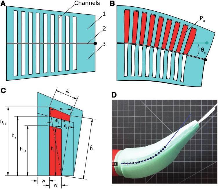
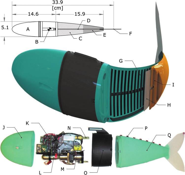
76                                                                                                        MARCHESE ET AL.

FIG. 1. Details of a soft-
bodied robotic fish. Top: A
dorsal view of the fish
showing (A) rigid anterior,
(B) center of mass, (C) an-
terior trunk musclelike actu-
ator pair, (D) inextensible
vertebrate-like constraint, (E)
posterior trunk actuator pair,
and (F) passive caudal fin.
Center: A cross-sectional
rendering of the mechanism
showing (G) fluidic elasto-
mer channels grouped into
antagonistic actuator, (H)
flexible constraint layer, and
(I) pressurized elastomer
channels in agonistic actua-
tor. Bottom: An exploded
view of the robot detailing
( J) silicone skin, (K) com-
munication and control elec-
tronics, (L) compressed gas
cylinder and regulator, (M)
flow control valves, (N) ac-
tuator access port, (O) plastic
fuselage, (P) videography
markers, and (Q) silicone
elastomer trunk.

performed maneuvers have a similar input–output relation-       however, such fully actuated, rigid-bodied systems inher-
ship as observed in biological fish.                            ently fail to capture the continuum motion of the escape
   Performance and autonomy are competing goals in fluid-       response maneuver.
powered soft robots. Some fluid-powered soft machines show         We build on several prior works that aim to create ro-
promising capabilities such as walking10 and leaping11 but      botic fish using biologically inspired flexible posteriors. Self-
are primarily driven by cumbersome external hardware lim-       propelling flexible foils driven by an external robotic actuator
iting their practical use. Conversely, there are instances of   have been studied by Lauder and colleagues.23,24 Valdivia y
self-contained fluidic soft robots;12–14 however, because of    Alvarado and Youcef-Toumi used a compliant body in the
the constraints imposed by bringing all supporting hardware     design of a robotic fish to mimic the swimming kinematics of
onboard, performance of these robots is severely limited        a natural fish.25 Similarly, the robot fish FILOSE26,27 has a
when compared with rigid-bodied robots. The primary             compliant posterior and serves as a test bed for fishlike
technical challenge addressed by this work is the advance-      sensing and locomotion. Both of these systems are cable-
ment of soft-bodied robots to simultaneously be capable         driven and actuated with an onboard servomotor but lack
of rapidly achieving continuum-body motion and be self-         autonomy and require an external power supply. Recently,
contained. We illustrate our proposed technical approach by     researchers have developed a cable-driven, flexible spring-
designing and building a soft robot fish capable of emulating   steel spine to model escape response behavior;28 however, in
the escape response of fish because this maneuver ex-           this system the motor, control system, and power supply are
emplifies rapid and continuum-body motion and exhibits the      external to the apparatus, and its motion is constrained. Long
highest accelerations seen in fish.1                            et al. have developed a flexible biomimetic vertebral column
   The soft robotic fish exhibits continuum motion that         used to propel an autonomous surface-swimming robot.29
conventional rigid-bodied robotic fish cannot achieve. For      The vehicle can also perform an escape response.30 Again, a
instance, although many notable robotic fish exist,15–19        single servomotor is used to actuate the compliant spine.
these prior robotic systems have bodies composed of rigid       Although this system is autonomous, relative to the afore-
segments connected by fixed joints and are consequently         mentioned work, only a small portion of the body is flexible,
incapable of reproducing the body kinematics observed           namely, its posterior tail, and because its large anterior is a
during agile escape response maneuvers. Previous at-            surface vessel, the system is limited to surface swimming.
tempts to recreate an escape response used a body com-          Notably, the above-mentioned compliant-bodied robotic fish
posed of multiple position-controlled, rigid links;20–22        operate on the principle of a passive, flexible mechanism
AUTONOMOUS SOFT ROBOTIC FISH CAPABLE OF ESCAPE MANEUVERS                                                                              77

driven by a traditional electromechanical actuator, and they        ments in these subsystems enable autonomous operation of a
were primarily designed to understand the hydrodynamics of          soft-bodied robot underwater.
the flexible body. However, in this work our primary goal was
to develop a fluidic actuation system that is embedded within
                                                                    Actuation
the flexible body, yielding a compliant and active body within
a completely self-contained system.                                    FEA technology forms the core of the soft-bodied robotic
   We have also built on prior work that introduced compliant       fish. FEAs are elastomer modules that bend under fluid
active-bodied robotic swimmers. Shen et al. have used an            pressure. Bending is accomplished using a two-layer bimorph
oscillating strip of ionic polymer–metal composite as the           structure. Pressurized gas expands fluidic channels embedded
posterior trunk of a dolphinlike robot.31 This is a free-           within an elastomer layer, and a second inextensible but
swimming robot, but again limited by an external tether.            flexible layer functions to constrain the axial tension gener-
Perhaps the closest precursor to our work is the Airacuda fish      ated by the expanding channels along one side. This trans-
developed by Festo.32 This robot has a flexible body and is         forms lateral stress in the elastomer into a bending moment.
driven by fluidic actuators. Similar to our system, the fluidic     Moreover, three layers can be used to form a bidirectional
and electronic components are located in the fish’s rigid an-       bending FEA: an inextensible constraining layer sandwiched
terior, and its actuators extend along the length of its flexible   between both an agonistic and antagonistic expanding layer,
trunk. However, this system differs considerably from ours in       as has been demonstrated in Ref.12 This bidirectional FEA
design. It is composed of a plastic skeleton covered by flex-       structure is fundamental to the soft robotic fish (see Fig. 1G,
ible skin with two actuators along the anteroposterior axis,        agonistic layer; H, constraining layer; and I, antagonistic
whereas we have a body composed almost entirely of soft             layer). However, in this work we have advanced FEA tech-
rubber with numerous actuators embedded in the dorsoven-            nology by abandoning a simple rectangular shape and cre-
tral orientation along the anteroposterior axis (see the Ac-        ating FEAs that conform to the complex anatomical shape of
tuation section in Materials and Methods). Another                  a fish. The structure and operating principles of a tapered
difference is that Airacuda can do static diving and swim-          bidirectional FEA are illustrated schematically in Figure 2.
ming using the onboard pneumatic actuation system, whereas             In their model, Onal and colleagues13 describe the total
the focus of the fish presented here was on forward swimming        bending angle h of a rectangular FEA using both the physical
and planar escape response maneuvers.                               properties of the channels and internal actuator pressure Pa,
   The work presented in this article differs from this prior
work in design, fabrication, and control, to enable new au-                                             we(r)
                                                                                       h ¼ 2n tan  1           ,
tonomous capabilities for soft robotic fish. Specifically, the                                           2hc
main contributions of this article include the following:                                                                        (1)
                                                                                                           hc

                                                                                                 r ¼ Pa          :
    A novel fluidic soft actuation system capable of rapidly                                            ha  hc
    achieving continuum-body motion
   A method for designing, fabricating, and controlling               Here, n is the number of channels, w is channel width, e is
    autonomous, self-contained soft-bodied robots                   material strain and a nonlinear function of material stress r,
   A self-contained soft robot device that embodies our            and, lastly, ha and hc are the constant heights of the actuator
    approach to soft robots and emulates forward swim-              and channels, respectively. However, because our actuator
    ming and planar escape maneuvers of biological fish,            differs considerably from a rectangular actuator with uniform
    along with experimental evaluations of the robot                channels, we have developed a new model. By extending the
                                                                    model presented in Ref.13 to include variable channel height as
                                                                    well as radial stress (i.e., normal to the inextensible constraint
Materials and Methods                                               layer), we can statically model the nonuniform bending of a
System overview                                                     tapered FEA (Fig. 2). Specifically, the accumulated angle
                                                                    along the length of the actuator after a given embedded
   A defining characteristic of the soft-bodied robotic fish        channel n, represented as hn, can be estimated as a function of
is the separation of actuation power from the rest of the           both the physical properties of the preceding channels and Pa,
system—specifically, the utilization of mechanical energy in
the form of pressurized fluid instead of electrical energy to                                      n
power actuation. The body of the robotic fish (Fig. 1C–E, G–                                hn ¼ + ai  F i ,                        (2)
I, and Q) is entirely composed of fluidic elastomer actuators                                     i¼1
(FEAs),13,33,34 which are directly powered by pressurized
fluid and accordingly no energy conversion takes place at the                       0                              1
actuators. However, in order to control the fluidic system,                              b                     b
                                                                           n           b2i
                                                                                  1B w
                                                                                           2             2
                                                                                       þ hi  1 þ w þ hi C       2
                                                                                                                           1    w
supporting valve hardware is also incorporated into the ar-         hn ¼ + cos @         qffiffiffiffiffiffiffiffiffiffiffiffiffiffiffiffiffiffiffiffi     A  tan              ,
chitecture to electrically address and isolate the mechanical            i¼1         2hbi hbi 2 1 þ w2                        hbi 1
actuation system.
                                                                                                hi
   The soft robot has onboard all the subsystems of a con-                     b i ¼ w e Pa
                                                                               w                         þ 1 , hbi ¼ hi [e(Pa ) þ 1]:
ventional robot: an actuation system, power system, driving                                     2w
electronics, and computation and control systems. These                                                                               (3)
systems (Fig. 1K–N) are stored in the fish’s rigid anterior
region (A), a region with minimal contribution to body cur-           Here, i is the channel index, ai and Fi are construction
vature during escape responses.35 Technological advance-            angles for the indexed channel, w and ŵ represent the initial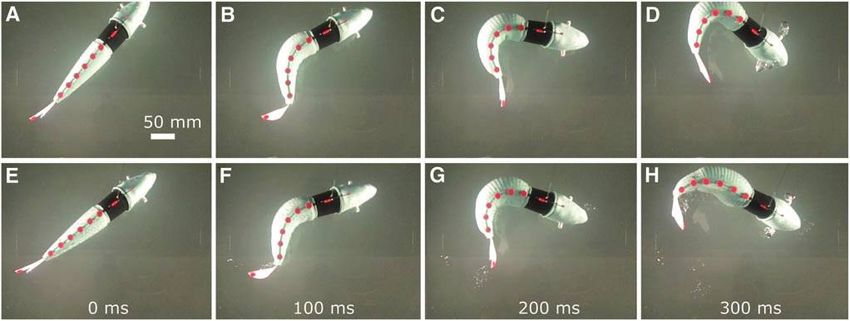
78                                                                                                          MARCHESE ET AL.

FIG. 2. Schematic repre-
sentation of a tapered bidi-
rectional FEA in cross
section. (A) The three-layer
structure: symmetric agonis-
tic (1) and antagonistic (3)
expanding layers sandwiching
an inextensible but flexible
constraining layer (2). Here,
embedded channel groupings
are in a depressurized state.
(B) Pressurized gas (red) ex-
panding the agonistic channel
group. Because of the con-
straining layer, fluid pressure
induces a bending moment
producing curvature. (C)
Model parameters. (D) Pre-
dicted curvature of the fish’s
anterior actuator overlaid atop
the actuator’s actual defor-
mation. FEA, fluidic elasto-
mer actuator.

and deformed widths of the indexed channel, and h and ĥ              This static analysis suggests that by independently varying
represent the initial and deformed heights of the indexed          the height of embedded channels, net complex curvatures of
channel. These parameters are illustrated in Figure 2C. It is      the body can be achieved. A curvature profile can be me-
important to note that this simplifying static model assumes       chanically ‘‘programmed’’ into the body geometry of the fish.
that channels deform purely by extending their side and top        Such construction serves to simplify computational control
walls, and that these wall stresses are based on initial channel   inputs. For instance, a single binary control input can be used
geometry. In reality, the wall stresses change as the channel      to drive the robot’s body through a complex kinematic profile
surfaces deform. For this reason, this analytic model is most      (Fig. 7).
valid for small deformations, that is, when pressure is low and       The robotic fish used in this case study employs four sili-
the actual stresses approximate those calculated from initial      cone FEAs that are molded to replicate the slender anatomy
channel geometry. The model also ignores external forces           of a natural fish, creating an actuated but continuously de-
such as the compressive forces generated by the antagonistic       formable body. The actuated body spans 43% to 100% of
half of the actuator. In Figure 2D we show a predicted             the robot’s overall fork length (30.5 cm) (Fig. 1, top). Em-
bending of the fish’s anterior actuator overlaid on top of the     bedded fluidic channels are grouped into two independently
actuator’s actual bending. Here, hn was predicted to be 52         actuated pairs: an agonistic and antagonistic anterior trunk
degrees but measured approximately 45 degrees. Table 1 lists       pair ranging from 45% to 70% of fork length (Fig. 1C), and a
actuator-specific parameter values for this experiment.            posterior trunk pair ranging from 70% to 90% of fork length
                                                                   (Fig. 1E). Separating the agonistic and antagonistic channel
                                                                   groups is an inextensible but flexible constraining layer in-
      Table 1. Physical Parameters of the Soft                     troduced along the fish’s posterior midline (Fig. 1D and H).
                 Anterior Actuator                                 This layer enables channel stresses to generate body curvature,
Parameter                                               Value      analogous to, though inverted from, the process by which
                                                                   muscles generate a bending moment about the vertebrate
Pa                                                    55.8 kPa     column in a fish.3,4
n                                                        16           A fabrication process was developed to first cast and then
h1                                                    18.6 mm      combine components of the fish’s soft body. The process is
h16                                                   11.8 mm      illustrated in Figure 3. First, each half of the body is cast
ha - h1                                                2.5 mm      from silicone rubber (Mold Star 15; Smooth-on, Easton,
ha - h16                                               1.8 mm      PA) by a two-part mold. The top mold piece creates the
w                                                      2.5 mm
h[n]                                                     52       embedded channels of both the anterior and posterior ac-
                                                                   tuator grouping, and the bottom piece creates the anatomical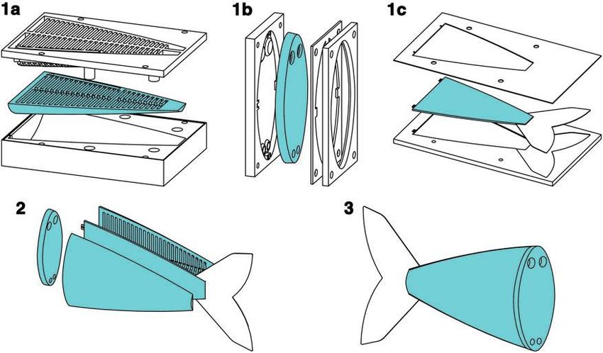
AUTONOMOUS SOFT ROBOTIC FISH CAPABLE OF ESCAPE MANEUVERS                                                                                   79

FIG. 3. Illustration of the soft fish body fabrication process. First, two halves of the body (1a), a connector piece (1b), and
a constraining layer (1c) are all cast from silicone by two-part molds. Next, these four pieces are sequentially bonded
together using a thin layer of silicone (2). Lastly, once cured, the fish body is ready for operation (3).

fish shape (Fig. 3[1a]). In parallel, a connector piece is cast                               Z       vD
with holes to serve as access ports to each channel grouping                   WResistive ¼                (Pai (v)  PaBaseline (v))dv:   (5)
and with an internal faceplate, allowing the connector to                                         0
mate with the fish’s rigid anterior (Fig. 3[1b]). In addition, a
thin constraint layer is cast with an embedded 0.5 mm                  Figure 4 shows the pressure–volume profiles at various flow
Acetal film that provides inextensibility and also forms the        rates as well as an illustration of the work calculations. Table 2
caudal fin (Fig. 3[1c]). Next, the four pieces undergo post-        lists the total, elastic, and resistive components of work done on
casting preparation and are sequentially bonded to each             the soft body in water at various flow rates. Here, work is
other using a thin layer of silicone (Fig. 3[2]). Once cured,       calculated according to Equations 4 and 5 not measured di-
the body is ready for attachment to the rigid anterior              rectly. The resistive component of work increases as the actu-
(Fig. 3[3]).                                                        ator is driven at higher rates; however, even at the highest rate of
   As mentioned, fluid energy is used to actuate the robot’s        actuation, nearly 78% of delivered energy is stored elastically.
body. Work is done on the body by the onboard power sys-
tem. When the body is actuated, a portion of this work              Power supply
is stored as potential energy within the elastomer and com-
pressible fluid, WElastic, and the remainder is dissipated be-         In order to drive locomotion, there must be an apparatus
cause of friction inside and outside the body, WResistive. In       onboard for supplying fluidic power. In an autonomous soft
order to characterize the relative amounts of work required to      robot application, it is desirable to maximize the energy
actuate the body at various rates, a pressure–volume analysis       density ( MJ
                                                                               L ) of the power supply. As a solution, we expand on
technique was used similar to that used to measure the work         our approach in Ref.14 and again use an 8 g CO2 gas cylinder
of breathing.36 While submerged in water, the agonistic an-         (PN 80121; Leland Ltd., Inc., South Plainfield, NJ) housing
terior actuator was repeatedly filled to a target volume, VD, as    fluid at high pressure and low volume (Fig. 5A). In this form,
the flow rate into the actuator was varied, ranging from a          a relatively large amount of fluidic energy can be stored in a
baseline flow of 5 L/m to a maximum flow of 50 L/m. Both            volume suitable for storage onboard the robot.
the change in internal actuator pressure, Pa, and change in            The total potential energy stored within, E, and energy
volume, v, were measured. We assume that at the baseline            density, D, of the high-pressure container can be theorized by
flow rate, there are no resistive losses and all energy delivered   assuming that the energy release is isothermal and by ne-
to the actuator is stored elastically,                              glecting fluid phase changes,
                             Z vD                                                                            R vf
                                                                                           E                  v0    Ps (v) dv
                  WElastic ¼       PaBaseline (v) dv:         (4)                        D¼ ¼                                   :          (6)
                             0                                                             V                         V

   At each flow rate above baseline, i, the resistive component       Here, the supply pressure Ps is a nonlinear function of
of work done on the body can be approximated as                     volume v, and this relation is defined using the Van der Waals
80                                                                                                                  MARCHESE ET AL.

                                                                               Table 2. Elastic and Resistive Components
                                                                               of Work Done on the Soft Body in Water
                                                                         Mass                Total             Elastic          Resistive
                                                                         flow (L/m)         work ( J)         work (%)          work (%)
                                                                         5                    2.89              100                 0
                                                                         10                   3.11               93.5               6.5
                                                                         20                   3.36               87.1              12.9
                                                                         30                   3.60               81.9              18.1
                                                                         40                   3.69               80.6              19.4
                                                                         50                   3.88               77.7              22.3

                                                                                              DP ¼ Pd  Pa ¼ qghT                      (7)

                                                                           where q is the fluid’s density, g the gravity, and hT the total
                                                                         head loss of the fluid delivery system, defined as,
FIG. 4. Pressure–volume profiles of fluid used to fill the                                                                !
anterior agonist actuator at various flow rates. By integrating
                                                                                               n   8Q2 fi Li    m
                                                                                       hT ¼ + 2 4            þ + Ki, j                 (8)
the change in pressure as a function of displaced volume, the                               i ¼ 1 p di g di    j¼1
elastic and resistive components of work done on the actu-
ator are determined.
                                                                            where i indexes the n serial pathways within the fluid de-
                                                                         livery system, L and d are the length and diameter of the
gas law. The volume v0 is the fluid’s volume corresponding to            pathway, Kj the loss coefficients of a pathway containing m
the vapor pressure of the gas, Ps(v0) = Pvapor. The volume vf is         losses, and f the friction factor as defined by the Haaland
the fluid’s volume at standard temperature and pressure. The             equation.37
volume occupied by the container is V. Table 3 contains ap-                 Specifically, we calibrate Equation 8 to characterize the case
plication-specific parameters for the power supply. According            of maximum excursion. Here, the anterior agonistic control
to Equation 6, the estimated energy density of this power                valve is fully open, the antagonistic valve is fully occluded, and
supply is 0.1 ( MJ
                L ), and the estimated total energy stored is 1.86       for simplicity we ignore the posterior actuator pair. The fluid
kJ. Although a typical lithium polymer battery has an energy             pathway has three main parts: (1) the section between the reg-
density of 0.9–1.5 ( MJL ), electrical energy is not suitable for        ulator and valve orifice, (2) the valve, and (3) the valve to the
directly powering FEAs; in such a case, the energy must first            actuator inlet. Pathways 1 and 3 are designed to minimize re-
be converted to the fluid domain using supporting hardware,              sistance and accordingly contribute little to hT. However, con-
occupying additional volume and imposing energy losses. This             straints on valve performance and size force pathway 2 to be of
motivates our use of a fluidic power supply.                             high resistance. Finite element analysis was used to estimate
                                                                         losses (SK) (see Table 3 for parameter estimates). As a result of
Gas delivery                                                             this analysis, DP is required to be between 0.06 and 0.10 MPa,
   Both an onboard gas regulation mechanism{ shown in Figure             and considering the range of Pa in Figure 4 and commercial
5B and delivery system (Fig. 5C and D) are required to dis-              availability, a regulator providing a Pd of 0.29 MPa was chosen.
tribute the stored fluid to the robot’s actuators. First, the fluid is      The above analysis suggests that the gas delivery system is
regulated to a suitable driving pressure, Pd, an order of mag-           responsible for considerable resistive energy losses. Given an
nitude below supply pressure. Subsequently, gas flows through            anterior actuator frequency of f, we can estimate the losses of
a series of control valves and into the body actuators. The              this subsystem over a single bidirectional actuation cycle:
network of valves and fluid pathways between the regulator and           EResistive ¼ (Pd  Pa )Q 1f : On the basis of experimental data
actuators resist fluid flow. Consequently, inlet flow Q to the           detailed in Figure 4, we can expect losses of around 50 J per
actuators is driven by DP, the pressure gradient between Pd, and         cycle while driving the anterior actuators during forward
the actuator’s internal pressure Pa. To ensure that Pd is of             swimming.
sufficient magnitude to drive the body through its target kine-
matic profile, a relationship between Q and DP is theorized.             Processing and control
   From our analysis in Figure 4, inlet flows of between 30                The robot contains an onboard microprocessor{ and
and 50 L/m are required for several hundred milliseconds.                wireless communication modulex that enable it to both pro-
Within the gas delivery system, Reynolds numbers are in                  cess external inputs and execute control policies. This com-
excess of 3 · 104, above the critical Reynolds number of                 putational system interfaces directly with onboard hardware
2.3 · 103, indicating turbulent flow. Assuming fully devel-              such as control valves and any available sensors. Two pro-
oped turbulent flow as well as constant fluid density, vis-              portional valves** are used to control the pressurization of
cosity, and temperature, we can estimate the DP required to
drive Q as follows:
                                                                           {
                                                                            Atmega 644P (Atmel Corporation, San Jose, CA).
                                                                           x
                                                                            XBee-PRO 900 (Digi International Inc., Minnetonka, MN).
  {
      0.29 MPa regulator (PN 50044; Leland Ltd., Inc.).                    **PN 921-111051-000 (Parker Precision Fluidics).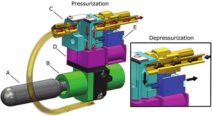
AUTONOMOUS SOFT ROBOTIC FISH CAPABLE OF ESCAPE MANEUVERS                                                                           81

                                                                                             FIG. 5. Details of gas storage,
                                                                                             regulation, and release mechanism.
                                                                                             The mechanism consists of a high-
                                                                                             pressure CO2 gas cylinder (A), a
                                                                                             passive mechanical regulator (B),
                                                                                             an interface manifold (C), propor-
                                                                                             tional control valves (D), and ex-
                                                                                             haust valves (E). On the left, red
                                                                                             arrows illustrate gas flow during
                                                                                             actuator pressurization; on the
                                                                                             right, black arrows illustrate gas
                                                                                             flow during depressurization.

the agonistic and antagonistic anterior actuators, and two         Results
exhaust valves{{ control depressurization. Two solenoid            Locomotion
valves{{ control pressurization and depressurization of the
posterior actuator pair. Depressurization of the body actua-          As mentioned, the fish’s body can function as an under-
tors is primarily passive. The exhaust and solenoid valve          actuated system, where a single control input can excite
orifices resist fluid outflow, and the actuators act as fluid      multiple modes of motion. Using just the anterior actuator
energy storage devices, analogous to a capacitor in the            pair as opposed to all four available actuators for forward
electrical domain. If we ignore the fluid’s negligible inertia,    swimming allows the fish to conserve the limited fluid energy
we can represent actuator depressurization as an undriven          stored onboard. Similar to the work of Valdivia y Alvarado
first-order system, analogous to a capacitor discharging           and Youcef-Toumi,25 our fish can use anterior trunk actuators
through a resistor. The instant the exhaust valve is open, the     to excite movement in the entire compliant body, producing
pressure gradient driving exhaust flow is equal to Pa, and the     fast forward swimming. During the experiment detailed in
flow is at a maximum. Subsequently, the flow exponentially         Figure 6, the fish operated using an open-loop controller, and
drops to zero. Although the computational system can pro-          its objective was to swim in a straight line. Here, the posterior
vide onboard autonomy, the robot wirelessly communicates           trunk actuator pair was passive, the anterior trunk actuators
with a host PC to receive user commands. The fish is nega-         were periodically driven at 1.67 Hz, and linear velocities
tively buoyant and held at a fixed submergence by means of a       of 150 mm/s, or 0.44 body lengths/s, were attained. Ap-
floating support.                                                  proximately 30 tail beats were available from the 8 g CO2
   The control policy of fully actuated fish locomotion can be     cylinder under these experimental conditions. Forward lo-
described using seven parameters, T1, M1, T2, M2, u, T3, and       comotion performance parameters were measured using a
T4. The anterior control valves are driven using a square-
wave input, and agonistic and antagonistic valves are ener-
gized sequentially ensuring while one actuator is pressurizing        Table 3. Robot Parameters Used in Modeling
the other is exhausting. Here, T1 and T2 are the open periods        Fluid Energy Supply and Fluid Delivery System
of the anterior agonistic and antagonistic actuator propor-
tional control valves, respectively. The corresponding orifice     Parameter                                               Value
magnitudes M1 and M2 of these control valves are defined as a
percent of maximum available flow. The parameter u is the          v0                                                    42.7 mL
phase delay between the anterior and posterior actuator pairs,     vf                                                     4.37 L
                                                                   Ps(v0)                                                6.08 MPa
and T3 and T4 are the open periods of the posterior agonistic      V                                                     18.6 mL
and antagonistic actuator control valves, respectively, and        q                                                    1.83 kg/m3
their magnitudes are fixed. However, the body can also be          d1                                                    4.72 mm
driven as an underactuated system where fewer than the total       d2                                                    2.75 mm
number of available actuators are used. For forward loco-          d3                                                    4.72 mm
motion, this abbreviated policy can be parameterized using         L1                                                     61 mm
only T1, M1, T2, and M2. For escape responses, this policy can     L2                                                     3.5 mm
be further reduced to using only T1 and M1. During escape          L3                                                     83 mm
responses, the posterior agonistic actuator is also used, but T3   f1                                                     4.7E-3
is set equal to T1.                                                f2                                                     4.4E-3
                                                                   f3                                                     4.7E-3
                                                                   SK1                                                      2.35
  {{
                                                                   SK2                                                      4.79
    PN PND-05A-12 (Parker Precision Fluidics).                     SK3                                                      4.76
  {{
    PN 914-232123-000 (Parker Precision Fluidics).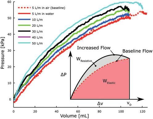
82                                                                                                        MARCHESE ET AL.

                                                                 Experiments were conducted to investigate the escape re-
                                                                 sponse of our soft-bodied robotic fish and compare its ma-
                                                                 neuvers to that of natural fish. A total of 28 escape response
                                                                 experiments are reported and were carried out in a 76-cm-
                                                                 long by 76-cm-wide by 61-cm-tall water tank filled to 41 cm.
                                                                 The robot was completely submerged and held at an initial
                                                                 fixed submergence by means of a 172-cm-long nylon string.
                                                                 Escape responses were generated using an open-loop con-
                                                                 troller. Escape response performance parameters were mea-
                                                                 sured using the same high-speed videography techniques as
                                                                 listed for the forward locomotion experiment; however, here
                                                                 the camera was positioned overhead. Heading angle is de-
                                                                 fined in degrees as the rotational displacement of the rigid
                                                                 anterior midline. Escape angle is defined as the resulting
FIG. 6. Experimental results of the robotic fish during          heading angle after the maneuver when the angular rate drops
forward swimming. The top panel shows the digitized av-          to zero. Linear escape velocity is defined as the Cartesian
erage body midline position moving as a function of time.        velocity of the center of mass 500 ms after the onset of the
The bottom panel details the corresponding linear velocity       maneuver.
of the center of mass as a function of time. During this            Fish 30–40 cm in length (rainbow trout and northern pike)
experiment, tail stroke frequency is 1.67 Hz, and a velocity     have been shown to perform type I, or single-bend, escape
of approximately 150 mm/s is attained.                           responses where the body initially bends into an ‘‘S’’ shape
                                                                 and subsequently into a ‘‘C’’ shape with heading angles
                                                                 greater than 90 degrees.38 Our robot exhibits fishlike mech-
high-speed video camera and a mirror mounted at 45 degrees
                                                                 anisms to accelerate (see the exemplary single-bend escape
underneath the robot. Video was recorded at 300 fps, and nine
                                                                 response in Figures 7A–D and 8A). We create single-bend
colored points along the robot’s dorsal midline were digitized
                                                                 responses by using only the anterior and posterior agonistic
during postprocessing.
                                                                 body actuators. Here, from 0 to 150 ms the body’s midline
   The forward-swimming results show that the self-
                                                                 assumes an ‘‘S’’ shape with the caudal fin curving in the
contained actuation system is capable of sustained operation,
                                                                 opposite direction of the trunk. From 150 to 500 ms the
exemplified by forward fishlike locomotion. However, the
                                                                 body’s midline assumes a ‘‘C’’ shape as the caudal fin, pe-
swimming gait we present here is certainly suboptimal. A
                                                                 duncle region, and trunk exhibit the same direction of cur-
comprehensive sweep over driving pressures, tail frequen-
                                                                 vature. The robot reaches a maximum heading angle of 100
cies, and body stiffness would allow optimization of forward
                                                                 degrees at approximately 520 ms. The aforementioned natu-
locomotion.
                                                                 ral fish also exhibit type II, or double-bend, escape responses
                                                                 characterized by the fish’s anterior region bending away from
Escape response
                                                                 the posterior midline’s primary direction of curvature as the
   A critical behavior exhibited among fish is an escape re-     body assumes a ‘‘C’’ shape.38 In Figures 7E–H and 8B, the
sponse, which involves rapidly bending the fish’s body to        robot performs a double-bend escape response using both
large angles in order to accelerate away from adverse stimuli.   anterior and posterior agonistic and antagonistic body

FIG. 7. Sequences depicting the soft robotic fish performing both a single-bend (A–D) and double-bend (E–H) escape
response. The single-bend response requires only agonistic actuator effort. The double-bend response requires sequential
agonistic and antagonistic actuator efforts, causing a significant decrease in heading angle and ultimately resulting in lower
escape angles than single-bend responses. Actuator effort durations of 160 ms were used in both escape responses.
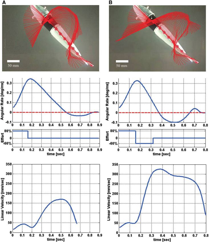
AUTONOMOUS SOFT ROBOTIC FISH CAPABLE OF ESCAPE MANEUVERS                                                               83

FIG. 8. Escape response kinematics of the soft-bodied robotic fish. Panel (A) details kinematics of a typical single-bend
escape response for the robotic fish; similarly, panel (B) details a double-bend escape response. The top portions of the
panels show the digitized body midline (red) overlaid every 10 ms from the first detectable motion to the end of maneuver.
The middle portions show the corresponding angular velocity of the head along with actuator effort (agonistic is positive;
antagonistic is negative). At the bottom is the resulting center-of-mass velocity for each maneuver.
84                                                                                                             MARCHESE ET AL.

FIG. 9. Fast-start kinemat-
ics of an angelfish. At the top
is the body midline plotted
for a single-bend (A) and a
double-bend (B) fast-start. At
the bottom is the corre-
sponding angular velocity
profile for the double-bend
fast-start. These figures are
reproduced with permission
from Domenici and Blake39
and Domenici and Blake,1
respectively.

actuators. Here, the ‘‘C’’ shape is assumed at 170 ms and is          completion of antagonistic activity). Onset of significant
quickly preceded by the body straightening. A maximum                 center-of-mass motion occurred at 160 ms, approximately
heading angle of 72 degrees is obtained at 410 ms. In general,        synchronized with the onset of antagonistic activity.
the robotic fish exhibits higher escape angles in single-bend            A point of contrast is that in natural fish the head and tail
than in double-bend escape responses. Figure 9 portrays both          both move toward each other in the first stage of the escape
a single- and double-bend escape response of an angelfish             response (Fig. 9). However, because the center of mass of our
(body length of 7.3 cm) exhibiting a similar kinematic pattern        robot is in the anterior head region, head movement is
to our robot; that is, the angelfish is also shown to have higher     greatest during the second stage of the escape response.
escape angles in single-bend than in double-bend re-                     Eaton, Lee, and Foreman’s direction-change hypothesis in
sponses.39                                                            natural fish41 is consistent with the behavior of our robotic
   Foreman and Eaton40 document that single-bend maneu-               fish. Specifically, a combination of agonistic and antagonistic
vers in fish result in higher escape angles and slower center-        actuator inputs can independently influence both escape
of-mass motion, while double-bend maneuvers result in                 angle and linear escape velocity during the robot’s escape
lower escape angles and faster center-of-mass motion. Con-            response. A series of experiments were carried out to inves-
sequently, although antagonistic effort is not required for           tigate the effect of two parameters, T1xx and M2, on the escape
center-of-mass motion, it is responsible for amplifying the           angle and linear escape velocity of the robotic fish (Fig. 10).
center-of-mass motion and a period of negative angular rate           As a result we found that T1 has marked influence on escape
in natural fish. An important result is that our robot exhibits       angle. Mean escape angle at T1 equal to 100 ms was 26.6
similar behavior: In double-bend responses, escape angle is           degrees, whereas mean escape angle was 81.4 degrees at T1,
lower and linear escape velocity higher than in single-bend           equal to 160 ms. Also, M2 provides control over escape angle.
responses. In double-bend escape responses having antago-             Increasing M2 decreased escape angle (Fig. 10A). Unlike
nistic actuator activity (Fig. 8B), the escape angle is reduced,
as there is significant angular rate in the negative (antagonistic)
                                                                        xx
direction starting at approximately 380 ms (60 ms after the              T1 = T2 in all tests.
AUTONOMOUS SOFT ROBOTIC FISH CAPABLE OF ESCAPE MANEUVERS 85
musclelike actuators generate curvature in a continuously
deformable, vertebrate-like body. Novel, form-independent
actuator technology as well as miniaturization of supporting
hardware enable the robot to take on the fundamental ana-
tomical structure of a fish while being self-contained and
unconstrained.
The programmability of our system allows repeatable
evaluation of the robot’s escape response maneuvers. By
directly controlling the duration and magnitude of agonistic
and antagonistic actuator efforts and measuring the resulting
escape response performance, we conclude that agonistic
duration has strong authority over escape angle and minimal
authority over linear escape velocity. Antagonistic magni-
tude has nonlinear control authority over both escape angle
and escape velocity. Increasing agonistic effort duration al-
lows for greater angular displacement of the head to be
reached during the first stage of the response. Soon after this
duration of time, the robot’s head begins to decelerate. The
longer the agonistic effort is applied, the greater the escape
angle. When antagonistic effort magnitude increases, there is
more energy to decelerate the turn and consequently escape
angle lowers. The antagonistic effort also provides the pro-
pulsive stroke, so greater antagonistic effort yields higher
escape velocity.
Evidence suggests that a similar input–output relationship
holds in biological escape response behavior. Consistent with
our robotic system, Foreman and Eaton40 presented the di-
rection change concept, where they show that escape re-
sponse heading angle is a function of the relative magnitudes
and timings of agonist and antagonist muscle contractions.
Wöhl and Schuster42 investigated the predictive start of
hunting archer fish and showed that in the underlying C-start
behavior, escape angle and escape velocity need to be de-
coupled. Also in line with our robotic system, Tytell and
Lauder43 found that, among investigated variables, stage-one
FIG. 10. Input–output relationship of escape response duration correlated most strongly with escape angle and that
maneuvers in the robotic fish. (A) Escape angle as a function antagonistic effort magnitude correlated most strongly with
of antagonistic actuator effort. (B) Escape velocity as a escape velocity in biological fish.
function of antagonistic actuator effort. In both cases, equal Our findings also suggest that despite the apparent com-
duration agonistic and antagonistic efforts of 100 and plexity of the maneuver, it is feasible that a robotic system
160 ms were used (blue and red lines, respectively). Data with limited onboard computational power could determine
points represent mean values (n = 4 and n = 3 for 100 and required escape response control parameters in real time and
160 ms scenarios, respectively, for a total of 28 tests), and
error bars represent standard deviations. with no a priori planning. Because the robot’s escape re-
sponse performance outputs, angle and velocity, are inher-
ently decoupled by the physical form of the body and
structure of the maneuver, control parameters could poten-
escape angle, T1 has minimal influence on linear escape ve- tially be computed onboard. For instance, the maneuver may
locity, mean values of 193.1 and 207.2 mm/s for 100 and start in immediate response to a perceived external stimulus
160 ms, respectively. However, M2 provided control over with a predetermined maximal agonistic effort. As this effort
linear escape velocity in that increasing effort level expo- occurs, the desired escape angle and velocity may be com-
nentially increased velocity (Fig. 10B). These findings indi- puted relative to the perceived stimuli. Accordingly, the
cate that through a combination of agonistic and antagonistic control variables T1 and M2 can be determined given a
actuator efforts, escape angle and linear escape velocity can mapping similar to that provided in Figure 10.
be independently altered. Given a fixed maximal agonistic
effort level, altering T1 and M2 can independently influence
Acknowledgments
both the resulting escape angle and escape velocity.
A special thanks to Robert Katzschmann from the Dis-
tributed Robotics Laboratory and the Soft Robotics reviewers
Discussion
for their extensive feedback. This work was done in the
The robotic fish provides an instantiation of our approach Distributed Robotics Laboratory at MIT with support from
to creating autonomous soft-bodied robots capable of rap- the National Science Foundation (grant numbers NSF
idly achieving continuum-body motion. In this system, soft IIS1226883 and NSF CCF1138967) and National Science86 MARCHESE ET AL.
Foundation Graduate Research Fellowship Program (primary mimetics fish robot. IEEE/ASME International Conference
award number 1122374). We are grateful for this support. on, July 14–17, 2009. Adv Intell Mechatronics 2009;1230–
1235.
Author Disclosure Statement 19. Wen L, Wang TM, Wu GH, Liang JH. Hydrodynamic in-
vestigation of a self-propelled robotic fish based on a force-
The authors declare no competing financial interests exist. feedback control method. Bioinspir Biomim 2012;7:
036012.
References
20. Lui J, Hu H. Mimicry of sharp turning behaviours in a
1. Domenici P, Blake RW. The kinematics and performance of robotic fish. Proceedings of the 2005 IEEE International
fish fast-start swimming. J Exp Biol 1997;200:1165–1178. Conference on Robotics and Automation (ICRA), 2005.
2. Borazjani I, Sotiropoulos F, Tytell ED, Lauder GV. Hy- 21. Xu JX, Ren Q, Gao W, Niu XL. Mimicry of fish swimming
drodynamics of the bluegill sunfish C-start escape response: patterns in a robotic fish. 2012 IEEE International Sym-
three-dimensional simulations and comparison with ex- posium on Industrial Electronics (ISIE), 2012.
perimental data. J Exp Biol 2012;215:671–684. 22. Su Z, Yu J, Tan M, Zhang J. A closed-loop method to
3. Wakeling JM, Johnston IA. Body bending during fast-starts generate fast C-start for a robotic fish. 2011 International
in fish can be explained in terms of muscle torque and Conference on Mechatronics and Automation (ICMA),
hydrodynamic resistance. J Exp Biol 1999;202:675–682. Beijing, China, 2011.
4. Jayne BC, Lauder GV. Red and white muscle activity 23. Lauder GV, Flammang B, Alben S. Passive robotic models
and kinematics of the escape response of the bluegill of propulsion by the bodies and caudal fins of fish. Integr
sunfish during swimming. J Comp Physiol A 1993;173: Comp Biol 2012;52:576–587.
495–508. 24. Alben S, Witt C, Baker TV, Anderson E, Lauder GV.
5. Webb PW, Skadsen JM. Strike tactics of Esox. Can J Zool Dynamics of freely swimming flexible foils. Phys Fluids
1980;58:1462–1469. 2012;24:38–62.
6. Walker JA, Ghalambor CK, Griset OL, McKenney D, 25. Valdivia y Alvarado P, Youcef-Toumi K. Design of ma-
Reznick DN. Do faster starts increase the probability of chines with compliant bodies for biomimetic locomotion
evading predators? Funct Ecol 2005;19:808–815. in liquid environments. J Dyn Sys Meas Control 2006;
7. Gibb AC, Swanson BO, Wesp HM, Landels C, Liu C. 128:1–2.
Development of the escape response in teleost fishes: do 26. El Daou H, Salumae T, Toming G, Kruusmaa M. Bio-
ontogenetic changes enable improved performance? Phsiol inspired compliant robotic fish: design and experiments.
Biochem Zool 2006;79:7–19. IEEE International Conference on Robotics and Automa-
8. Domenici P, Turesson H, Brodersen J, Bronmark C. Pre- tion (IEEE ICRA 2012), St. Paul, Minnesota, 2012.
dator-induced morphology enhances escape locomotion in 27. El Daou H, Salumae T, Ristolainen A, Toming G, Listak
crucian carp. Proc R Soc Ser B 2008;275:195–201. M, Kruusmaa M. A bio-mimetic design and control of a
9. Bergstrom CA. Fast-start swimming performance and re- fish-like robot using compliant structures. The 15th IEEE
duction in lateral plate number in threespine stickleback. International Conference on Advanced Robotics (ICAR
Can J Zool 2002;80:207–213. 2011), Tallinn, 2011.
10. Shepherd RF, Ilievski F, Choi W, Morin SA, Stokes AA, 28. Feng C, Bonafilia BR, Modarres-Sadeghi Y, Triantafyllou
Mazzeo AD, Chen X, Wang M, Whitesides GM. Multigait MS. The mechanics of fast-start performance of pike
soft robot. Proc Natl Acad Sci USA 2011;108:20400– studied using a mechanical fish. Proceedings of the ASME
20403. 2011 International Mechanical Engineering Congress &
11. Shepherd RF, Stokes AA, Freake J, Barber J, Snyder PW, Exposition IMECE2011, Denver, Colorado, 2011.
Mazzeo AD, Cademartiri L, Morin SA, Whitesides GM. 29. Long JH, Koob T, Schaefer J, Summers A, Bantilan K,
Using explosions to power a soft robot. Angew Chem Grotmol S, Porter M. Inspired by sharks: a biomimetic
2013;125:2964–2968. skeleton for the flapping, propulsive tail of an aquatic robot.
12. Onal CD, Rus D. Autonomous undulatory serpentine lo- Mar Technol Soc J 2011;45:119–129.
comotion utilizing body dynamics of a fluidic soft robot. 30. Long JH, Krenitsky NM, Roberts SF, Hirokawa J, de
Bioinspir Biomim 2013;8:026003. Leeuw J, Porter ME. Testing biomimetic structures in
13. Onal CD, Chen X, Whitesides GM, Rus D. Soft mobile bioinspired robots: how vertebrae control the stiffness of
robots with on-board chemical pressure generation. Inter- the body and the behavior of fish-like swimmers. Integr
national Symposium on Robotics Research (ISRR), Flag- Comp Biol 2011;51:158–175.
staff, AZ, August 28–September 1, 2011. 31. Shen Q, Wang T, Liang J, Wen L. Hydrodynamic perfor-
14. Marchese AD, Onal CD, Rus D. Towards a self-contained mance of a biomimetic robotic swimmer actuated by ionic
soft robotic fish: on-board pressure generation and em- polymer–metal composite. Smart Mater Struct 2013;22:
bedded electro-permanent magnet valves. Exp Rob 2013; 075035.
88:41–54. 32. Festo. Airacuda, 2006. Available at: www.festo.com/cms/
15. Liu J, Hu H. Biological inspiration: from carangiform fish en_corp/9761.htm (accessed Dec. 31, 2013).
to multi-joint robotic fish. J Bionic Eng 2010;7:35–48. 33. Correll N, Onal CD, Liang H, Schoenfeld E, Rus D. Soft
16. Barrett DS, Triantafyllou MS, Yue DKP, Wolfgang MJ, autonomous materials—using active elasticity and embed-
Grosenbaugh MA. Drag reduction in fish-like locomotion. J ded distributed computation. Springer Tracts Adv Rob
Fluid Mech 1999;392:183–212. 2014;79:227–240.
17. Triantafyllou M, Triantafyllou G. An efficient swimming 34. Marchese AD, Onal CD, Rus D. Soft robot actuators using
machine. Sci Am 1995;272:64–70. energy-efficient valves controlled by electropermanent
18. Zhong Y, Chong CW, Zhou C, Seet G, Low KH. Perfor- magnets. IEEE/RSJ International Conference on Intelligent
mance predict model for a body and caudal fin (bcf) bio- Robots and Systems (IROS), San Francisco, CA, 2011.AUTONOMOUS SOFT ROBOTIC FISH CAPABLE OF ESCAPE MANEUVERS 87
35. Spierts IL, Van Leeuwen JL. Kinematics and muscle dy- 42. Wöhl S, Schuster S. The predictive start of hunting archer
namics of c-start and s-starts of carp (Cyprinus carpio l.). J fish: a flexible and precise motor pattern performed with the
Exp Biol 1999;202:393–406. kinematics of an escape C-start. J Exp Biol 2007;210:311–
36. Otis AB. The work of breathing. Physiol Rev 1954;34: 324.
449–458. 43. Tytell ED, Lauder GV. The C-start escape response of
37. Haaland SE. Simple and explicit formulas for the friction Polypterus senegalus: bilateral muscle activity and vari-
factor in turbulent. J Fluids Eng 1983;105:8990. ation during stage 1 and 2. J Exp Biol 2002;205:2591–
38. Harper DG, Blake RW. Fast-start performance of rainbow 2603.
trout Salmo gairdneri and northern pike Esox lucius. J Exp
Biol 1990;150:321–342.
39. Domenici P, Blake RW. The kinematics and performance Address correspondence to:
of the escape response in the angelfish (Pterophyllum ei- Andrew D. Marchese
mekei). J Exp Biol 1991;156:187–205. Department of Electrical Engineering
40. Foreman MB, Eaton RC. The direction change concept for and Computer Science
reticulospinal control of goldfish escape. J Neurosci 1993; Massachusetts Institute of Technology
13:4101–4113. 32 Vassar Street, Room 32-376
41. Eaton RC, Lee RKK, Foreman MB. The Mauthner cell and Cambridge, MA 02139
other identified neurons of the brainstem escape network of
fish. Prog Neurobiol 2001;63:467–485. E-mail: andy@csail.mit.eduYou can also read