Behaviour of Cold-Formed Z Purlins with Sag- Rods in Pre-Engineered Buildings - IJRASET
←
→
Page content transcription
If your browser does not render page correctly, please read the page content below

International Journal for Research in Applied Science & Engineering Technology (IJRASET)
                                                                        ISSN: 2321-9653; IC Value: 45.98; SJ Impact Factor: 6.887
                                                                        Volume 6 Issue V, May 2018- Available at www.ijraset.com

      Behaviour of Cold-Formed Z Purlins with Sag-
           Rods in Pre-Engineered Buildings
                          Kanchan S Takale1, Prof. R. V. R. K Prasad2, Dr. Ramesh V. Meghrajani3
                                           1
                                          Mtech Student, Civil Engg. Dept., KDKCE, Nagpur
                                       2
                                         Asso. Professor, Civil Engg. Dept., KDKCE, Nagpur,
                                   3
                                     Principal Consultant, NEO Infrastructure Consultants, Nagpur

Abstract: Zee profile has a complex deformation behaviour and the severe buckling issues leads to reduction in strength of the
member. Lateral torsional buckling is the governing deformation leading to overall distortion of the member. It is important to
eliminate or delay these buckling problems to achieve higher sustainability of the structure. Use of Sag-rods is a common
practice adopted to curb this lateral torsional buckling and to reduce the unbraced length of the member. In this paper the
deformed shape of the Zee profile is thoroughly observed. While analysing, both the flange widths are kept unbraced since a
standard practice of providing 300mm spacing in roofing connection along the length of the purlin is not genuinely practiced
everywhere. The influence of one and two sag rods on the deformed shape of Zee profile is observed. The focus was set on the
longitudinal deformations of the member with regards to the distribution of deformations along the length of the member. A
comparative study of the same is presented in this paper.
Keywords: BM (Bending moment), TD (Total deformation), XD (X-directional deformation), YD (Y-directional deformation),
ZD (Z-directional deformation).

                                                       I. INTRODUCTION
The use of cold-formed steel structures is very popular around the world for its faster and standard manufacturing and construction
techniques offering economy. However, the behaviour of these thin gauged members is characterised by a range of buckling modes
such as local buckling, lateral torsional buckling and distortional buckling specially in case of roof framing members, viz., purlins.
Zee profile is the most recommended section for purlins due to its special characteristic of overlapping and nesting into each other
forming an intact system of roof bracings. But, Zee profile has a complex deformation behaviour and the severe buckling issues
leads to reduction in strength of the member. Lateral torsional buckling is the governing deformation leading to overall distortion of
the member. Therefore, it is important to eliminate or delay these buckling problems to achieve higher sustainability of the structure.

                       II. GEOMETRICAL CONFIGURATIONS AND GENERAL ARRANGEMENTS

                                   Fig. 1 Representation of Zee profile on global axis of ANSYS

 ©IJRASET: All Rights are Reserved                                                                                                        1482
International Journal for Research in Applied Science & Engineering Technology (IJRASET)
                                                                         ISSN: 2321-9653; IC Value: 45.98; SJ Impact Factor: 6.887
                                                                         Volume 6 Issue V, May 2018- Available at www.ijraset.com

                                                              TABLE I
                                                  ZEE PROFILES AVAILABLE IN INDIA
                                        PARAMETER          SYMBOL UNIT         Z1     Z2     Z3         Z4     Z5
                           1   OVERALL DEPTH                   D    mm          200    200    230        230    250
                           2   WIDTH OF FLANGE                 B    mm           60     60     60         60     70
                           3   LENGTH OF LIP                   L    mm           20     20     20         20     22
                           4   THICKNESS OF MEMBER             t    mm          1.5    1.6      2        2.2     2.5
                           5   INNER RADIUS OF CURVATURE       r    mm            3      3      3          3       3

                        Fig. 2 Influence of length on total deformations in Zee profiles available in INDIA
                                            TABLE II Zee profile selected for analysis
                                             PARAMETER             SYMBOL UNIT                    Z1
                                   1          Overall depth                d          mm          200
                                   2         Width of flange               b          mm          60
                                   3          Length of lip                c          mm          20
                                   4      Thickness of member              t          mm          1.5
                                   5    Inner radius of curvature          r          mm           3
                                   6      Length of the member             L          mm      8000

The study from boundary conditions revealed that the practical condition of constraining four cleat holes is the best suit for the
definition of the problem. The exact boundary condition under which the Zee profile will be simulated is Pin-Pin with 1 additional
constraint at each end. The ideal loading condition was found to be SETUP B under which a force in KN is applied on the entire top
flange of the Zee Profile.
As the length of the member increases, the deflection increases. However, the maximum total deformations are found to be least for
Z5(250*70*22*25) of all members. But this being a heaviest section of all available sections, is avoided under normal condition.
Under huge wind pressure, like coastal areas prone to cyclones and mountainous terrain, use of section Z5 is recommended if no
other member fits in. For section Z1(200*60*20*15), which is a typical section, the deformations are observed to fall from 5.5 m of
length to 6.5m of length. The use of section is recommended to be used under all normal conditions for the best suited length range
of 5.5m to 7.5m.
The comparison of Zee profile with and without lip element showed that Zee profiles with lip elements have higher strengths as the
deformations observed under identical loading conditions are less of Zee profile with lip elements compared to Zee profiles without
lip element. The Zee profile with lip element at 30° experiences the minimum deformations. In practice, the Zee profile with 45° is
used. A comparison of Zee profile with 30° and 45° lip angle was made. The Zee profile with 30° lip angle is found to be more
stable in regards of the deformations. Suitability of a 30° lip element while overlapping may be further studied to justify why the
45° lip angle Zee Profiles. Also, the load carrying capacities of the two may be compared. For further simulations, Zee profile with
45° lip angle is considered. However, a range of 30°-60° lip angle Zee Profiles is acceptable.

 ©IJRASET: All Rights are Reserved                                                                                                     1483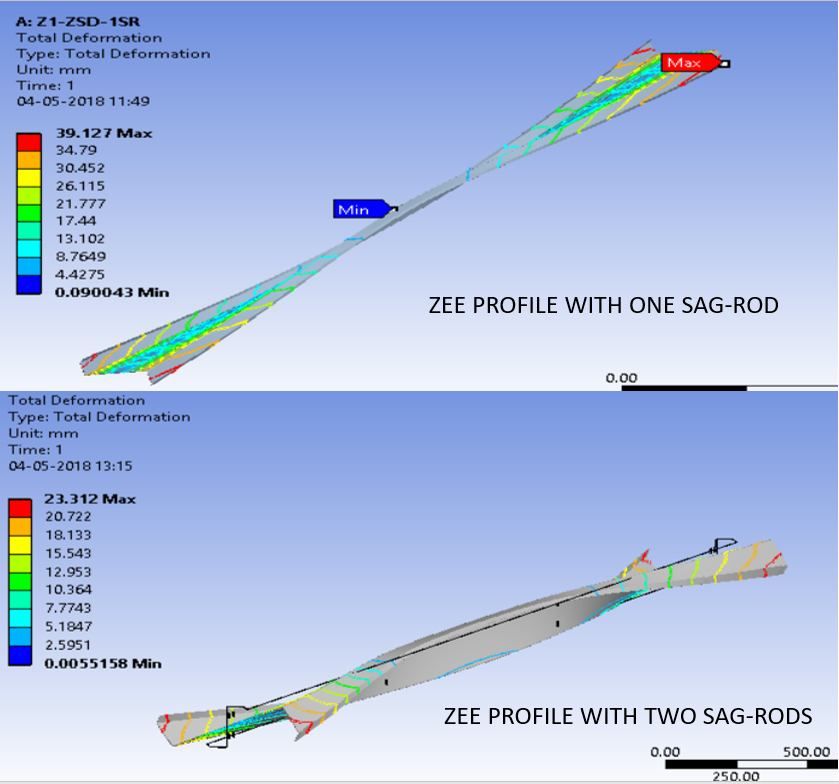
International Journal for Research in Applied Science & Engineering Technology (IJRASET)
                                                                       ISSN: 2321-9653; IC Value: 45.98; SJ Impact Factor: 6.887
                                                                       Volume 6 Issue V, May 2018- Available at www.ijraset.com

                           Fig. 3 Portrayal of deformed shape of Zee profile with both flanges unbraced
The portrayal of deformed shape of Zee profile give the deformed shape of Zee profile at a cross-section cut at the midspan length
of the member. (4m). The entire cross-section is housed in 17 points. Point 1-2-3 (16.09-12.99-11.10) mm house for lower lip, point
3-4-5-6-7 (11.10-6.77-15.44-16.14-16.19) mm houses for bottom flange, point 7-8-9-10-11 (16.19-22.09-39.99-60.21-81.20) mm
house for web, point 11-12-13-14-15 (81.20-82.72-83.60-86.94-91.79) mm house for top flange and points 15-16-17 (91.79-90.34-
89.14) mm houses for upper lip.

                        III. STUDY DEFORMED SHAPE OF ZEE PROFILE WITHOUT SAG RODS

                                                              UNBRACED LENGTH OF
                                                                 THE MEMBER
                50
               200
               100
                50

                              END 1                                                                            END 2
                                 Fig. 4 Geometrical configuration of Zee profile without Sag-rods
To study the deformations at various cross-sections of the Zee profile, six sections have been considered viz., C/S @ 0-0, C/S @ CC
(Connection Centre), C/S @ 1M, C/S @ 2M, C/S @ 3M and C/S @ 4M along the length of the member starting from end 1.
From Fig. 5, it is observed that the maximum deformation occurs at midspan at the outer edge of top flange. Local buckling can be
observed in both the unbraced flanges. The, web however presents a straight line. Studies suggests that under lateral torsional
buckling the cross-sectional elements may show a rigid behaviour. In Fig. 5, the appeared behaviour in the web is rigid like. It is
possible for the web element to behave as a rigid body under lateral torsional buckling, which in the above example exist. To ensure
the result, a study of deformed shape of only web element is performed.

 ©IJRASET: All Rights are Reserved                                                                                                     1484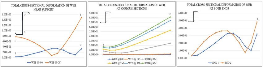
International Journal for Research in Applied Science & Engineering Technology (IJRASET)
                                                                         ISSN: 2321-9653; IC Value: 45.98; SJ Impact Factor: 6.887
                                                                         Volume 6 Issue V, May 2018- Available at www.ijraset.com

                               Fig. 5 Total cross-sectional deformation of Zee profile without sag-rods

                                Fig. 6 Local buckling in web of Zee profile at various cross-sections
From Fig. 6, local buckling is observed in the web at C/S @ 0-0 where point 1 is pinned vertex. The maximum total deformation is
observed at point 2. It must be noted that, local buckling is observed at the point 1 where the pinned vertex as the name suggests, is
restricted to lateral displacements in all directions. From Fig. 5, the rigid cross-sectional behaviour of the web is observed at all the
sections subjected lateral torsional displacements. The section WEB @ 0-0 and WEB @ CC has been discussed above. A
comparison of web cross-section is done at End 1 and End 2. The behaviour is similar, local buckling is observed. The slight
variation in the curvature is the effect of variation in directional deformations (Z-directional deformations causing torsional effect
longitudinally).

 ©IJRASET: All Rights are Reserved                                                                                                          1485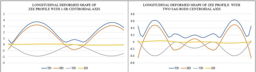
International Journal for Research in Applied Science & Engineering Technology (IJRASET)
                                                                     ISSN: 2321-9653; IC Value: 45.98; SJ Impact Factor: 6.887
                                                                     Volume 6 Issue V, May 2018- Available at www.ijraset.com

                         IV. STUDY DEFORMED SHAPE OF ZEE PROFILE WITH SAG RODS

                                 Fig. 7 Geometrical configuration of Zee profile with sag-rods

           Fig. 8 Longitudinal total deformations of centroidal axis and top flange of Zee profile with 1-SR and 2-SR
1) With one sag rod, the maximum deformation of the member is reduced from 99.917mm to 39.127mm. the maximum total
   deformation is on the end points with two one rods.
2) Twisting behaviour of the member is observed.
3) Uneven distribution of deformations along length.

 ©IJRASET: All Rights are Reserved                                                                                               1486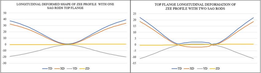
International Journal for Research in Applied Science & Engineering Technology (IJRASET)
                                                                      ISSN: 2321-9653; IC Value: 45.98; SJ Impact Factor: 6.887
                                                                      Volume 6 Issue V, May 2018- Available at www.ijraset.com

                      Fig. 9 Twist formed at the ends of the Zee profile showing maximum total deformation
4) With two sag rods, the maximum deformation of the member is reduced from 99.917mm (with no sag rod) and 39.127mm
   (with two sag rods) to 23.00mm. The maximum total deformation is on the end points with two sag rods.
5) Twisting behaviour of the member is observed.
6) Even distribution of deformations along length.
7) Maximum deformations on the end points can be taken care of by overlapped section
   The comparative study is performed on Zee section profile Z1(200*60*20*15) of 8 metres length.
   It is observed that the maximum deformation of Zee profile with one sag rod is at the end points and not on the midspan. That
   would generate a negative bending moment at the support. This negative bending moment is the peak value of BM in the
   member. At this junction, the effect of this comparatively huge BM can be reduced with overlap. An overlap at the junction will
   impart the benefit of doubled cross-sectional area and correspondingly doubled strength.

                                                   V. CONCLUSIONS
                                TABLE III Influence of sag-rods on deformations of Zee profiles
                                COMPARATIVE STUDY OF ZEE PROFILE WITH AND WITHOUT SAG RODS

                                            PARAMETER                0-SR        1-SR        2-SR

                               Total Deformation          Minimum       0.006       0.090       0.006
                                                       mm Maximum      99.917      39.127      23.312

                               C/S @ 0-0                  Minimum        0.006      0.695       0.466
                                                       mm Maximum        2.213     37.871      23.005

                               C/S @ CC                   Minimum        0.132      0.492       0.362
                                                       mm Maximum        3.202     37.459      22.487

                               C/S @ 4M                   Minimum       6.369       0.995       0.183
                                                       mm Maximum      99.917       0.316       4.023

                               Centroidal                 Minimum       0.561       0.185       0.114
                                                       mm Maximum      43.989       3.738       0.637

                               Top Flange Outer Edge      Minimum       1.686       0.752       0.615
                                                       mm Maximum      99.917      39.127      21.921

                               Stress                      Minimum      0.639       0.777       0.292
                                                       Mpa Maximum    364.750     271.180     166.940

                               Strain                     Minimum     0.00005     0.00001     0.00001
                                                          Maximum     0.00220     0.00136     0.00084

 ©IJRASET: All Rights are Reserved                                                                                                   1487
International Journal for Research in Applied Science & Engineering Technology (IJRASET)
                                                                                        ISSN: 2321-9653; IC Value: 45.98; SJ Impact Factor: 6.887
                                                                                        Volume 6 Issue V, May 2018- Available at www.ijraset.com

From TABLE III, it is observed that use of sag-rods not only reduces the total deformations in the Zee profile but also reduces the
stresses generated in the member. Use of sag-rods cannot completely eliminate the deformations of slender sections such as Zee
sections. But, it can considerably reduce the deformations to the limiting value as prescribed in the codes.

                                                   VI. ACKNOWLEDGMENT
With profound feeling of immense gratitude and affection, the author would like to thank Guide Prof. R.V.R.K. Prasad and Co-
Guide Dr. Ramesh V. Meghrajani for their enthusiasm, expertise guidance and encouragement throughout this study. Their
supervision with constructive criticism and confidence enabled author to complete this project. The author puts forth deepest sense
of gratitude towards Prof. Dr. R. N. Khapre, Shri Ramdeobaba College of Engineering, Nagpur for his guidance in ANSYS
simulations.

                                                                       REFERENCES
[1]    IS800:2007 (Indian Standard General Construction in Steel – Code of practice)
[2]    IS801:1975 (Indian Standard Code of practice for use of Cold-Formed Light Gauge Steel Structural Members in General Building Construction)
[3]    SP:6(5)-1980 (Handbook for Structural Engineers – 5. Cold-Formed, Light-Gauge Steel Structures.
[4]    IS875(Part3):2015 (Indian Standard Design Loads (Other than Earthquake) for Buildings and Structures – Code of Practice
[5]    BS 5950-5:1998 (Structural use of steelwork in building – Part 5 Code of practice for  design of cold formed thin gauged sections)
[6]    AISI Manual – 1998 (Cold-Formed Steel Design Manual
[7]    Steel Designers Manual – 200
[8]    AISI/AISC 360-16 (Specification for Structural Steel Buildings
[9]    A Newman “Metal Building Systems – Design and Specification”
[10]   Dr. N Subramanian “Steel Structures – Design and Practice”
[11]   Alomir H. Favero Neto, Luiz C.M. Vieira Jr., Maximiliano Malite “Strength and stiffness of cold-formed steel purlins with sleeved and overlapped bolted
       connections”, Thin-Walled Structures, March 2016
[12]   Lei Zhang, Gen-Shu Tong “Lateral bucking of simply supported C-and Z-section purlins with top flange horizontally restrained”, Thin-Walled Structures, 2015
[13]   W. Ye, C.J. Wang, D. J. Mynors, K. A. Kibble, T. Morgan, B. Cartwright, “Load-deflection behaviour of sleeved joints in modified Z purlin system”, Thin-
       Walled Structures, 2013
[14]   A. Biegus, “Causes of imminent failure damage and repair of Steel Building Purlins”, ELSEVIER – Archives of Civil and Mechanical Engineering, 2015
[15]   Xiao-ting Chu, Jamie Rickard, Long-yuan Li, “Influence of lateral restraint on lateral torsional buckling of cold-formed steel purlins”, ELSEVIER - Thin-
       Walled Structures, 2005
[16]   L Kemp, P E Dunaiski & W Bird, “Structural Behaviour of cold-formed profiles with emphasis on the Zeta-profile”, ELSEVIER - Journal of Construction and
       Steel Research, 1995.

  ©IJRASET: All Rights are Reserved                                                                                                                                  1488
You can also read