Behaviour of Polymer Filled Composites for Novel Polymer Railway Sleepers - MDPI
←
→
Page content transcription
If your browser does not render page correctly, please read the page content below
polymers
Article
Behaviour of Polymer Filled Composites for Novel Polymer
Railway Sleepers
Wahid Ferdous 1, * , Allan Manalo 1 , Choman Salih 1 , Peng Yu 1 , Rajab Abousnina 2 , Tom Heyer 3
and Peter Schubel 1

                                           1   Centre for Future Materials (CFM), University of Southern Queensland, Toowoomba, QLD 4350, Australia;
                                               Allan.Manalo@usq.edu.au (A.M.); Choman.Salih@usq.edu.au (C.S.); Peng.Yu@usq.edu.au (P.Y.);
                                               Peter.Schubel@usq.edu.au (P.S.)
                                           2   School of Engineering, Macquarie University, Macquarie Park, NSW 2113, Australia;
                                               rajab.abousnina@mq.edu.au
                                           3   Austrak Pty. Ltd., Brisbane, QLD 4001, Australia; Tom.Heyer@vossloh.com
                                           *   Correspondence: Wahid.Ferdous@usq.edu.au; Tel.: +61-7-4631-1331

                                           Abstract: A novel concept of polymer railway sleeper is proposed in this study that has the potential
                                           to meet static performance requirements within the cost of hardwood timber. The existing challenges
                                           of composite sleepers, such as low performance or high cost, can be overcome using this innovative
                                           concept. Such a proclamation is proven through limit state design criteria and a series of experimen-
                                           tations. Results show that polyurethane foam as an infill material can provide sufficient strength and
                                           stiffness properties to the sleeper, but the inadequate screw holding capacity could be a problem.
                                           This limitation, however, can be overcome using a particulate filled resin system. The findings of this
                                           study will help the railway industry to develop a timber replacement sleeper.


                                           Keywords: composite sleeper; timber replacement sleeper; GFRP; structural performance; sustain-
Citation: Ferdous, W.; Manalo, A.;
                                           able development
Salih, C.; Yu, P.; Abousnina, R.; Heyer,
T.; Schubel, P. Behaviour of Polymer
Filled Composites for Novel Polymer
Railway Sleepers. Polymers 2021, 13,
1324. https://doi.org/10.3390/             1. Introduction
polym13081324                                   The global railway industry is looking for an alternative material railway sleeper
                                           that can replace traditional timber sleeper which is suffering from premature deteriora-
Academic Editor: Vincenzo Fiore            tion [1,2]. To take this as an opportunity, a number of research institutions and railway
                                           sleeper manufacturing companies in different parts of the world are developing innovative
Received: 28 February 2021                 polymer-based technologies. These alternative sleepers are mainly developed from recy-
Accepted: 15 April 2021
                                           cled plastics and fibre reinforced synthetic foam materials. Recycled plastic sleepers are
Published: 18 April 2021
                                           made of waste tyres, plastic bottles and other similar materials which is highly beneficial
                                           from the environmental viewpoint [3]. Moreover, this type of sleeper can be manufactured
Publisher’s Note: MDPI stays neutral
                                           within the cost of hardwood timber due to the use of high volume of waste materials. How-
with regard to jurisdictional claims in
                                           ever, they are suffering from low pull-out resistance, low stiffness, high thermal expansion
published maps and institutional affil-
                                           causing plastic deformation and subsequently loosening of fasteners, low fire resistance
iations.
                                           and poor dimensional stability at service temperatures [4]. On the other hand, the Fibre-
                                           reinforced Foamed Urethane (FFU) sleeper has very similar mechanical properties but
                                           superior durability than traditional timber sleepers [5–7]. However, their high cost (around
                                           5–10 times more expensive than standard timber sleepers [8]), limited shear strength due to
Copyright: © 2021 by the authors.
                                           the absence of transverse fibres and increasing concern for occupational health, safety, and
Licensee MDPI, Basel, Switzerland.
                                           environment (OHSE) [7] due to the generation of polyurethane dust during screw drilling
This article is an open access article
                                           are restricting their applications. Therefore, an alternative polymer-based material that
distributed under the terms and
                                           meets both cost and performance criteria for sleeper is inevitable.
conditions of the Creative Commons
                                                Ferdous et al. [9] investigated high performance polymer sleeper manufactured from
Attribution (CC BY) license (https://
                                           fibre composite sandwich panels and bonded with epoxy polymer matrix. The dog bone
creativecommons.org/licenses/by/
4.0/).
                                           shape of this sleeper was designed based on shape optimisation that reduced the volume

Polymers 2021, 13, 1324. https://doi.org/10.3390/polym13081324                                            https://www.mdpi.com/journal/polymers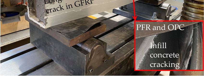
Polymers 2021, 13, 1324                                                                                                      2 of 13

                               of materials by up to 50% with respect to the rectangular shaped sleeper and was able to
                               be manufactured within target price range. A similar approach for shape optimisation
                               was considered for KLP (Kunststof Lankhorst Product) plastic sleepers which reduced the
                               volume of plastics by 35% compared with rectangular shaped solid sleeper [10]. However,
                               the railway industry prefers to replace timber sleeper by an alternative sleeper that looks
                               alike timber sleepers, i.e., the rectangular shaped sleeper is the preferred choice [11]. The
                               reason could be the rectangular shaped sleeper is easier to push into the ballast bed during
                               spot replacement (i.e., track maintenance work). Therefore, the key scientific research
                               challenge is how to develop an alternative material sleeper that will be rectangular in
                               shape and perform satisfactorily within the target price range. To achieve this goal, the
                               authors recently proposed three new concepts of internally reinforced rectangular shaped
                               composite sleepers [4]. However, the manufacturing process of internally reinforced
                               sleepers is complex and time consuming. Therefore, this study proposed a design concept
                               for an externally reinforced polymer railway sleeper to address the scientific challenge.
                               Moreover, a higher strength and stiffness can be achieved if the reinforcement is applied
                               externally. The outcome of this study will guide sleeper manufacturers to design a polymer
                               railway sleeper that is cheaper and faster in construction.

                               2. Development of the Sleeper Concept and Performance Evaluation
                               2.1. Selection of Suitable Polymer
                                    The commonly used polymeric resins for structural applications are epoxy, polyester,
                               vinyl ester, phenolic, polyurethane foam and some others. Several classes of synthetic resins
                               manufactured by the esterification of organic compounds are available. The advantage and
                               disadvantage of different resins are summarised in Table 1 to justify the selection of the most
                               suitable one for manufacturing railway sleepers. One of the major considerations is the cost
                               of resin which limits the choice among polyester, phenolic and polyurethane foam. The
                               quick and ease of application of resin for large scale sleeper manufacturing is an essential
                               requirement. Since the resin will be used as an infill material, moisture and UV are not of
                               major concern. Considering this fact, polyurethane foam was selected for this study.

                                Table 1. Advantage and Disadvantage of Different Resins [12].

         Types of Resin                          Advantage                                        Disadvantage

                           •     High mechanical and thermal properties
                           •     High water resistance                           •   More expensive than vinyl esters
             Epoxy         •     Long working times available                    •   Mixing is critical
                           •     High temperature resistance
                           •     Low cure shrinkage

                                                                                 •   Limited mechanical properties
                           •     Easy to use                                     •   High styrene emissions in open moulds
            Polyester      •     Low cost                                        •   Limited range of working times
                                                                                 •   High cure shrinkage

                                                                                 •   Postcure required for high properties
                           •     Very high chemical resistance                   •   High styrene content
           Vinyl ester     •     Higher mechanical properties than polyesters    •   Expensive than polyesters
                                                                                 •   High cure shrinkage

                           •     Good mechanical properties
                           •     Heat and impact resistant                       •   Very low toughness
            Phenolic       •     High chemical and moisture resistance           •   Brittle nature
                           •     Low cost                                        •   Humidity badly affects its resistance
                           •     Low smoke emission

                           •     Low cost
                           •     High thermal insulation properties              •   Spray foam insulation method might be
       Polyurethane foam   •     Quick and easy application                          expensive
                           •     Highly adhesive and extremely lightweight
                           •     Does not create dust or release harmful gases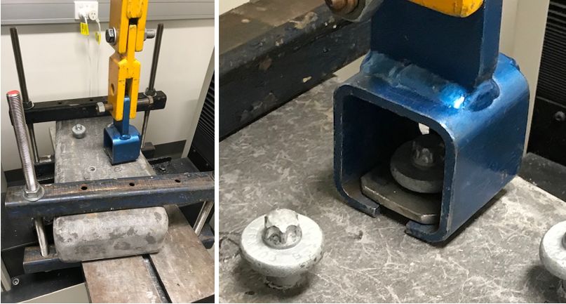
Polymers 2021, 13, x FOR PEER REVIEW 3 of 13
Highly adhesive and extremely lightweight
Polymers 2021, 13, 1324 Does not create dust or release harmful gases 3 of 13
2.2. Design of PU Foam Core FRP Sleeper (Concept-1)
This concept
2.2. Design of sleeper
of PU Foam is based
Core FRP on (Concept-1)
Sleeper a glass fiber reinforced polymer (GFRP) rectangu-
lar hollow pultruded section filled
This concept of sleeper is based on a glasswith polyurethane (PU) foam
fiber reinforced polymer as shown
(GFRP)in Figure 1.
rectangular
Inspired by the sleeper concept developed on the geopolymer concrete
hollow pultruded section filled with polyurethane (PU) foam as shown in Figure 1. Inspired filled GFRP tubes
[13],
by the sleeper concept developed on the geopolymer concrete filled GFRP tubes [13],geo-
the proposed concept is advantageous from screw drilling perspectives. While the
polymer
proposedconcrete
concept is is non-drillable,
advantageousthe fromPUscrew
foamdrilling
core allows on-site drilling
perspectives. which is an
While geopolymer
important
concrete iscriterion for spot
non-drillable, thereplacement
PU foam core of allows
deteriorated
on-sitesleepers.
drilling Moreover,
which is anthe exterior
important
polymer
criterion coated
for spot GFRP offers better
replacement thermal andsleepers.
of deteriorated fire resistance
Moreover,compare to recycled
the exterior plas-
polymer
tics which was identified a weakness for recycled plastic sleepers.
coated GFRP offers better thermal and fire resistance compare to recycled plastics which The cost of the GFRP
profile is dependent
was identified a weaknesson thefor wall thickness.
recycled plasticTosleepers.
determine The thecost
minimum
of the GFRPrequired wall
profile is
thickness,
dependentthe onsectional
the wallanalysis
thickness. is conducted
To determine (Figure
the 1). It is worth
minimum noting wall
required that the contri-
thickness,
bution of PU core
the sectional is ignored
analysis in the analysis
is conducted (Figure 1). dueItto
is its low noting
worth strength.thatThe
thestrain and stress
contribution of
profiles
PU core are plotted in
is ignored inthe
Figure 1 where
analysis due totheitssymbols have their
low strength. The usual
strain meanings. Table 2
and stress profiles
listed the properties
are plotted in Figure of GFRP the
1 where laminates
symbols fabricated
have their with
usualtenmeanings.
layers of fibres
Table oriented
2 listed thein
longitudinal
properties of(60%)
GFRPand 45-degree
laminates diagonal
fabricated with (40%) directions
ten layers withoriented
of fibres a fibre volume fraction
in longitudinal
(60%)
of 55%.and 45-degree diagonal (40%) directions with a fibre volume fraction of 55%.
Figure 1. Sectional
Sectional analysis
analysisofofsleeper
sleeperConcept-1
Concept-1 (ignoring
(ignoring thethe contribution
contribution of low
of low strength
strength infillinfill material
material thus athus a linear
linear strain
strain and distribution
and stress stress distribution for exterior
for exterior Fiber Reinforced
Fiber Reinforced PolymerPolymer
(FRP)).(FRP)).
Table 2. Nominal
Table 2. Nominal Properties of GFRP
Properties of GFRP Laminates.
Laminates.
Properties Value Unit
Properties Value Unit
Tensile failure strain 0.035 -
Tensile failure strain
Tensile failure stress 0.035 425 - MPa
Tensile failure stressmodulus
Tensile 425 16.5 MPa GPa
Tensile modulus 16.5 GPa
Compressive failure strain 0.025 -
Compressive failure strain 0.025 -
Compressive
Compressive failure stress
failure stress 280 280 MPa MPa
Compressive
Compressive modulus modulus 11.5 11.5 GPa GPa
The increase of sectional modulus and moment capacity with the increase of tube
thickness from 1 mm
The increase to 10 mm
of sectional are summarised
modulus and moment in Table 3. The
capacity withmoment capacity
the increase and
of tube
modulus
thicknessoffrom
elasticity
1 mm(MOE) of the
to 10 mm composite
are sleepers
summarised can be
in Table 3. as lowmoment
The as 25 kN-m [4] and
capacity 4
and
GPa [14], of
modulus respectively. Basedof
elasticity (MOE) onthe
thecomposite
compressive failure
sleepers canatbe
theastop
lowside ofkN-m
as 25 GFRP,[4]
Table
and 34
suggested that a thin layer
GPa [14], respectively. of GFRP
Based on thetube (even 1 mm)
compressive canatmeet
failure the side
the top requirements of mo-3
of GFRP, Table
ment capacity,
suggested that however, a minimum
a thin layer of GFRP tube thickness
(even 1of 4 mm
mm) canismeet
required to meet the target
the requirements MOE
of moment
capacity,
of 4 GPa. however, a minimum thickness of 4 mm is required to meet the target MOE of
4 GPa.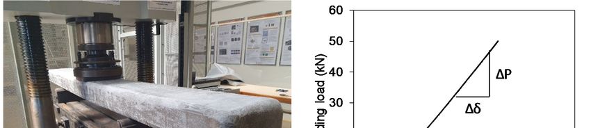
Polymers 2021, 13, 1324 4 of 13
Polymers 2021, 13, x FOR PEER REVIEW 4 of 13
Table 3. Increase of Sleeper Capacity with Tube Thickness.
Table
Tube 3. Increase ofNeutral
Thickness Sleeper Axis
Capacity with Tube Thickness.
Depth I Moment MOE
Tube Thickness Neutral Axis
mm Depth mmI mm4Moment kN-m MOE GPa
mm mm 1 mm4
61.09 kN-m
29490994 89 GPa 2.01
1 61.092 29490994
61.08 2948909889 175 2.01 2.73
2 61.083 29489098
61.06 175
29485321 258 2.73 3.41
3 61.064 29485321
61.04 258
29481565 339 3.41 4.07
4 61.045 29481565
61.02 339
29477830 416 4.07 4.70
5 61.026 61.00
29477830 29474117
416 491 4.70 5.30
6 61.007 60.98
29474117 29470424
491 563 5.30 5.86
7 60.988 60.96
29470424 29466753
563 633 5.86 6.40
8 60.969 60.93
29466753 29461286
633 699 6.40 6.92
9 60.9310 60.91
29461286 29457667
699 763 6.92 7.41
10 60.91 29457667 763 7.41
2.3. Materials and Manufacturing of Sleeper Concept-1
2.3. Materials
2.3.1. PU Foam and Manufacturing
and GFRP Laminates of Sleeper Concept-1
2.3.1.APU Foam
solid and GFRPmade
component Laminates
with polyurethane (PU) based resin was used as a core
material of sleeper
A solid (Figure
component 2a). with
made The typical compressive
polyurethane strength
(PU) based resinand
wascompressive
used as a core modulus
ma-
terial
of PU of sleeper
foam are 1(Figure
MPa and 2a).16
The typical
MPa, compressive
respectively strength
[15]. Two typesand compressive
of GFRP fabrics modulus
such as
of PU foam
uniaxial are 1 MPa
(0 direction andand60016gsm)
MPa,and
respectively [15]. Two
triaxial (0/+45/ −45types of GFRP
directional fabrics
fibres andsuch as
823 gsm)
uniaxial
were used (0 to
direction
fabricateandouter
600 gsm)
layerand triaxial
of the core.(0/+45/−45
Two layers directional fibres
(first and lastand 823 gsm)
layers) of non-
were usedchopped
structural to fabricate outermat
strand layer of the
(CSM) core. Two
fibreglass layers
were (first
used and last
together layers)
with GFRPof non-
fabrics.
structural chopped strand mat (CSM) fibreglass were used together
The very first layer of CSM was provided to ensure sufficient resin to the main GFRP layer with GFRP fabrics.
The better
and very first layer ofThe
bonding. CSM waslayer
final provided
of CSMto ensure sufficient to
was provided resin to the
avoid themain
dropGFRP layer
of resin due
and better bonding. The final layer of CSM was provided to avoid
to gravity and also for cosmetic elegance to the sleeper. The fibre stacking sequence the drop of resin duewas
to gravity and also for cosmetic elegance
CSM/U/T/U/U/U/T/U/CSM, where Utoand the Tsleeper. The unidirectional
represents fibre stacking sequence
and triaxialwasfab-
CSM/U/T/U/U/U/T/U/CSM,
rics, respectively. The lamination where U andwas
process T represents
done at the unidirectional and triaxial
Buchanan Advanced fabrics,
Composites
respectively.
(BAC) The lamination process was done at the Buchanan Advanced Composites
in Toowoomba.
(BAC) in Toowoomba.
(a) (b)
Figure2.
Figure 2. Manufacturing
Manufacturing process.
process. (a)
(a)Prefabricated
PrefabricatedPU
PUfoam
foamcore.
core.(b)
(b)Applying
ApplyingGFRP
GFRPfabrics onon PU
fabrics
PU core.
core.
2.3.2. Manufacturing
2.3.2. Manufacturing Method
Method
The
The PUPU core was prepared
prepared ininaaclosed
closedmould
mouldbefore
beforeapplying
applying laminates.
laminates. The PUPU
The core
core
waswrapped
was wrapped with
with GFRP laminates
laminates using
usinghand
handlamination
laminationprocess.
process.The Thewrapping
wrapping waswas
done by
done by two
two steps
steps to avoid
avoid sagging
saggingdueduetotogravity
gravity(a)
(a)applied
appliedonon two
two sides and
sides thethe
and toptop
surface and
surface and (b) flipped over
over and
andrepeat
repeatthethesame
sameprocess
process(i.e.,
(i.e.,applied
applied twotwosides and
sides andthethe
othersurface).
other surface). The
The fibres
fibres were
were overlapped
overlappedatattwotwosides
sidesofofthe
thesleeper
sleeper forfor
full depth.
full depth.
AA particulate
particulate filled
filledresin
resinmix
mixwaswasprepared using
prepared polyester
using polyester resinresin
(Polyplex 1472 In-
(Polyplex 1472
fusion Resin 25, density 1.10 g/cm 3), NOROX
3 CHM-50 hardener (density
Infusion Resin 25, density 1.10 g/cm ), NOROX CHM-50 hardener (density 1.06 g/cm ) 1.06 g/cm 3) and 3
and fly ash with a mixing ratio of Resin: Hardener: Fly ash = 2000:40:200 g. The resin and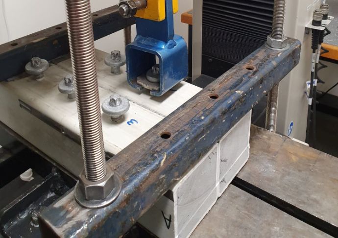
Polymers 2021, 13, 1324 5 of 13
Polymers 2021, 13, x FOR PEER REVIEW 5 of 1
hardener were mixed before the fly ash added to the mix. The gel time (working time) of
the resin mix wasflyaround 1 h.
ash with The samples
a mixing were post
ratio of Resin: curedFly
Hardener: 80 =◦ C
atash for 3 h. The
2000:40:200 overall
g. The resin and hard
casting process areener werein
shown mixed before
Figure the fly ashthe
2. Although added
GFRPto the mix. Thewere
laminates gel time (working
applied usingtime) of the
resin mixfor
hand lamination process wasthe
around 1 h. The
research samples were
purpose, post curedwas
the approach at 80 used
°C for to
3 h.simulate
The overall casting
pultruded hollow process are shown
rectangular in Figure
profiles 2. Although
for large the GFRP laminates were applied using hand
scale manufacturing.
lamination process for the research purpose, the approach was used to simulate pultruded
hollow rectangular profiles
2.4. Results and Discussion—Performance for largeofscale
Evaluation manufacturing.
Sleeper Concept-1
2.4.1. Density
2.4. Results and Discussion—Performance Evaluation of Sleeper Concept-1
The dimensions of the PU foam core sleeper were 243 mm (W) × 120 mm (D) ×
2.4.1. Density
2130 mm (L). The overall weight of the sleeper was 39 kg that provided an equivalent
The dimensions of the PU foam core sleeper were 243 mm (W) × 120 mm (D) × 2130
density of 640 kg/m3 . This density is lower than the density of traditional softwood timber
mm (L). The overall weight of the sleeper was 39 kg that provided an equivalent density
sleepers (855 kg/m3 ) and able to overcome the limitation of heavy weight for concrete
of 3640 kg/m3. This density is lower than the density of traditional softwood timber sleeper
sleepers (2000 kg/m ). Moreover,
(855 kg/m ) and able
3 the density is alsothe
to overcome slightly lower
limitation of than
heavythe recycled
weight plastic sleeper
for concrete
sleepers (850–1150(2000
kg/m 3 ) and close to FFU (fibre-reinforced foamed urethane) synthetic
kg/m ). Moreover, the density is also slightly lower than the recycled plastic sleeper
3
3 ) [10]. The lower
sleeper (740 kg/m(850–1150 kg/m3) anddensity
close toof
FFUthe(fibre-reinforced
proposed concept is due
foamed to the synthetic
urethane) use of sleepe
lightweight foam (740
core. The
kg/m lowThe
3) [10]. density
lower is preferable
density for ease concept
of the proposed of handling
is due sleepers but
to the use of lightweigh
might create trackfoam
stability
core.issue.
The low density is preferable for ease of handling sleepers but might create
track stability issue.
2.4.2. Bending Modulus of Elasticity (MOE)
2.4.2. Bending
Bending modulus Modulus
of elasticity of Elasticity
is an important (MOE)
property on which the deflection
characteristics of sleeper are dependent. The MOE isanthe
Bending modulus of elasticity is important
functionproperty on which
of the initial theof
slope deflection
the char
acteristics of sleeper are dependent. The MOE is the function
load-displacement curve obtained from midspan bending test. Therefore, a non-destructiveof the initial slope of the
load-displacement curve obtained from midspan bending test. Therefore, a non-destruc
test (Figure 3a) up to 50 kN was carried out under three-point bending with a span of
tive test (Figure 3a) up to 50 kN was carried out under three-point bending with a span o
1130 mm (same as narrow gauge length of sleeper).
1130 mm (same as narrow gauge length of sleeper).
Figure 3. Non-destructive
Figure 3. Non-destructivethree-point
three-pointbending
bending test (a) test
test (a) testsetup
setupand
and(b)
(b)load-displacement
load-displacement behaviour.
behaviour.
Figure 3b plotted Figure
the load-displacement curve where itcurve
3b plotted the load-displacement can where
be seen thatbe
it can the bending
seen that the bending
behaviour is almost linear upistoalmost
behaviour 50 kN linear
load. The
up toeffective modulus
50 kN load. of elasticity
The effective of theof
modulus sleeper
elasticity of the
was found 5.15 GPa as determined
sleeper was foundby Equation
5.15 (1), where a,
GPa as determined I and ∆P/∆δ
byL,Equation are shear
(1), where a, L, Ispan,
and ΔP/Δδ are
shear span,
span, effective moment span,ofeffective
of inertia moment
the sleeper, andof inertia
slope of the
of the sleeper, and slope curve,
load–displacement of the load–dis
placement
respectively. The MOE curve, respectively.
for softwood The MOE
timber sleeper can beforas
softwood
low as 7.4timber
GPa.sleeper can bethe
Moreover, as low as 7.4
GPa. Moreover, the MOE for recycled plastic sleeper varies
MOE for recycled plastic sleeper varies between 1.5 GPa and 1.8 GPa while it is 8.1 GPa between 1.5 GPa and 1.8 GPa
while it is 8.1 GPa for FFU synthetic sleeper [10]. The American
for FFU synthetic sleeper [10]. The American Railway Engineering and Maintenance-of- Railway Engineering and
Maintenance-of-Way Association (AREMA) specification indicated that the MOE for pol
Way Association (AREMA) specification indicated that the MOE for polymer composite
ymer composite sleeper should be at least 1.17 GPa [16]. The incorporation of fibres in PU
sleeper should be at least 1.17 GPa [16]. The incorporation of fibres in PU foam core sleeper
provided higher modulus than recycled plastic materials. However, the stiffness is slightly
lower than softwood timber and FFU due its lower density.
a 2 ∆P
2
MOE = 3L − 4a (1)
48I ∆δ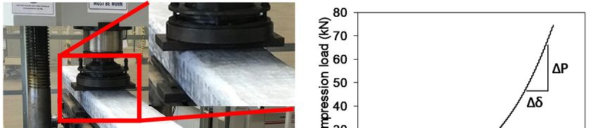
Polymers 2021, 13, x FOR PEER REVIEW 6 of 13
Polymers 2021, 13, 1324 foam core sleeper provided higher modulus than recycled plastic materials. However,
6 of 13 the
stiffness is slightly lower than softwood timber and FFU due its lower density.
∆
= (3 −4 )( ) (1)
48 ∆
2.4.3. Compression Modulus of Elasticity
2.4.3. Compression
The compression modulus ofModulus of Elasticity
elasticity of sleeper indicates the deformation charac-
teristics when the sleeper is being compressed.
The compression A non-destructive
modulus of elasticity rail-seat
of sleeper indicates the compression
deformation charac-
teristics
test was conducted when the sleeper
to determine is being compressed.
these properties. A non-destructive
The compression rail-seat4a)
load (Figure compression
was
test which
applied up to 72 kN was conducted to determine
is the design these
rail-seat properties.
load The compression
for narrow-gauge load (Figure
rail-track 4a) was
[9]. The
applied up to 72 kN which is the design rail-seat load for narrow-gauge rail-track [9]. The
sleeper was supported by two steel plates. The load was applied at mid-span due to the
sleeper was supported by two steel plates. The load was applied at mid-span due to the
homogeneous property along the length of the sleeper.
homogeneous property along the length of the sleeper.
Figure 4. Rail-seat compression
Figure 4. Rail-seat test (a)
compression test
test (a) setup andand
test setup (b)(b)
load-displacement behaviour.
load-displacement behaviour.
The compressionThe load-displacement behaviour is
compression load-displacement plotted is
behaviour inplotted
Figurein4b. The4b.
Figure compres-
The compres-
sion test providedsion test provided
a non-linear a non-linear load-displacement
load-displacement curve withcurve with increasing
increasing slope. Theslope. The initial
initial
slope up to 10 kN was linear and lower than other portions of the curve. This implies the
slope up to 10 kN was linear and lower than other portions of the curve. This implies
the specimen wasspecimen was locally compressed at the initial stage and the slope started to increase
locally compressed at the initial stage and the slope started to increase
thereafter due to stopping local compression. Therefore, the maximum slope in the entire
thereafter due to stopping local compression. Therefore, the maximum slope in the entire
load-displacement curve was used to determine the compressive modulus of elasticity
load-displacement curve
using was used
Equation (2). Into determine
this equation, D,theA compressive
and ΔP/Δδ are modulus
the depth of ofsleeper,
elasticity
effective
using Equation (2). In this equation, D, A and ∆P/∆δ are the depth
compression area and maximum slope of the load-displacement curve. Theof sleeper, effective
compressive
compression areamodulus
and maximum slope
of elasticity was of the load-displacement
obtained 450 MPa which is highercurve.than
Thethecompressive
same property for
recycled
modulus of elasticity wasplastic sleepers
obtained 450(176–269
MPa whichMPa) isbuthigher
lower than
than timber sleepers
the same (650 MPa)
property for [17].
Understanding the compressive modulus of sleeper is important
recycled plastic sleepers (176–269 MPa) but lower than timber sleepers (650 MPa) [17]. as the screw holding
ability of sleeper is dependent on this property.
Understanding the compressive modulus of sleeper is important as the screw holding
ability of sleeper is dependent on this property. ∆
= × (2)
∆
D ∆P
MOEcom = × (2)
2.4.4. Modulus of Rupture (MOR) A ∆δ
Modulus of rupture measures the load carrying capacity of sleeper in bending. The
2.4.4. Modulus oftest
Rupture (MOR) following the procedure described in the AS 1085.22 [18]. Two speci-
was conducted
Modulus of rupture
mens were measures the load
tested under centrecarrying capacity
point bending at a of sleeper
span of 600 in
mm bending.
until the The test
failure (Figure
was conducted following the procedure described in the AS 1085.22 [18]. Two specimens The
5a). It was observed that the specimens were failed in skin buckling and compression.
were tested under specimens failed bending
centre point in skin buckling due to
at a span ofthe
600discontinuation
mm until theoffailure
fibres in(Figure
the hand5a).
lamina-
tion manufacturing process. This could be avoided if the GFRP rectangular hollow profile
It was observed that the specimens were failed in skin buckling and compression. The
specimens failed in skin buckling due to the discontinuation of fibres in the hand lamination
manufacturing process. This could be avoided if the GFRP rectangular hollow profile is
made in a pultrusion process. The maximum load and displacement (Figure 5b) observed
from calibrated equipment were 325 kN at 11.1 mm for specimen-1 and 405 kN at 13 mm
for specimen-2, respectively, provided an average MOR of 94 MPa according to Equation
(3) where M is the average ultimate moment and c is the distance of outer fibre from the
neutral axis. The MOR obtained for this sleeper is significantly higher than the MOR of
softwood timber (22–34 MPa) and hardwood timber sleepers (55 MPa) [4].
Mc
MOR = (3)
I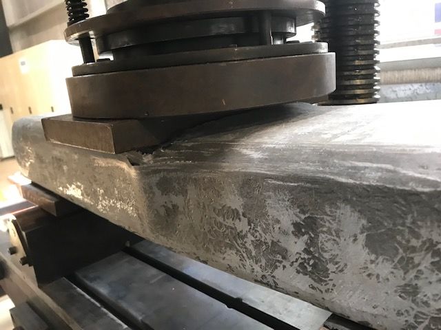
Equation (3) where M is the average ultimate moment and c is the distance of outer fibre
from the neutral axis. The MOR obtained for this sleeper is significantly higher than the
MOR of softwood timber (22–34 MPa) and hardwood timber sleepers (55 MPa) [4].
= (3)
Polymers 2021, 13, 1324 7 of 13
450
Specimen-1
400
Ultimate bending load (kN)
Specimen-2
350
300
250
200
150
100
50
0
0 5 10 15
Displacement (mm)
(a) (b)
Figure
Figure 5. Ultimate test 5. Ultimate
results. test
(a) Test results.
setup and (a)failure
Test setup and(b)
mode. failure mode. (b) Load-displacement
Load-displacement behaviour. behaviour.
2.4.5. Pull-Out Resistance
2.4.5. Pull-Out Resistance
Pull-out resistancePull-out
measuresresistance
the screwmeasures
holding the screw holding
capacity capacity
of sleeper. This isofan
sleeper. This is an im
important
portant property that ensures rail alignment in correct gauge.
property that ensures rail alignment in correct gauge. The pull-out resistance is determined The pull-out resistance is
determined based on the force required to pull-out the screw. Three standard 16 × 105 rai
based on the force required to pull-out the screw. Three standard 16 × 105 rail screws
screws (shank diameter 16 mm, underhead length 105 mm and shank length 35 mm) sup
(shank diameter 16 mm, underhead length 105 mm and shank length 35 mm) supplied
plied by Cold Forge Pty Ltd (Caringbah, NSW, Australia) were inserted into the sleeper
by Cold Forge Pty Ltd (Caringbah, NSW, Australia) were inserted into the sleeper. The
The test setup is shown in Figure 6a and the pull-out force and crosshead displacement is
test setup is shown in Figure
plotted 6a and
in Figure themaximum
6b. The pull-out pull-out
force and crosshead
resistance displacement
provided is
by three screws were
plotted in Figure 15.57
6b. The maximum pull-out resistance provided by three screws
kN, 12.78 kN, and 11.29 kN with an average of 13.2 kN (standard deviation 2.17) were
15.57 kN, 12.78 kN, and
This 11.29 kN
resistance withthan
is lower an average
the minimumof 13.2 kN (standard
pull-out resistancedeviation
of 22.2 kN 2.17).
required as per
This resistance isAREMA
lower than the minimum
specification pull-out
[16]. Moreover, theresistance
resistance isofalso
22.2 kN required
significantly lowerasthan the 40
per AREMA specification
kN pull-out [16]. Moreover,
resistance the for
required resistance
traditionalis also
timbersignificantly
sleeper as per lower than standard
AS1085.18
the 40 kN pull-out [19]. The low pull-out
resistance required resistance is due to the
for traditional low transverse
timber sleeper asshear
percapacity of the PU core
AS1085.18
Polymers 2021, 13, x FOR PEER REVIEW 8 of 13
standard [19]. The low pull-out resistance is due to the low transverse shear capacity of the
PU core.
18
Screw-1
16 Screw-2
Pull-out strength (KN)
14 Screw-3
12
10
8
6
4
2
0
0 2 4 6
Crosshead displacement (mm)
(a) (b)
Figure6.6.Pull-out
Figure Pull-outbehaviour.
behaviour.(a)
(a)Pull-out
Pull-outtest
testsetup.
setup.(b)
(b)Pull-out
Pull-outforce
forcevs
vsdisplacement.
displacement.
2.5.Findings
2.5. Findingsfrom
FromSleeper
SleeperConcept-1
Concept-1
ItItisisobvious
obviousthat
thatthe
thealternative
alternativesleeper
sleeperhashastotoperform
performsatisfactorily
satisfactorilyas
asper
perstandard
standard
requirements.
requirements. The The performance
performanceofofthethesleeper
sleeper Concept-1
Concept-1 obtained
obtained from
from the the extensive
extensive test-
testing program
ing program is is tabulated
tabulated ininTable
Table4.4.ItItcan
canbe
beseen
seenthat
that the
the bending modulus
modulusof ofelasticity
elasticity
and
andmodulus
modulusof ofrupture
ruptureofofthe
thePU
PUfoam
foamcore coreFRP
FRPsleeper
sleeper(Concept-1)
(Concept-1)satisfactorily
satisfactorilymeet
meet
the performance criteria while density and rail-seat compression modulus
the performance criteria while density and rail-seat compression modulus are slightly are slightly
lower than timber. However, the screw pull-out resistance is lower than the minimum
requirement as per AREMA specification for polymer composite sleeper. Therefore, a fur-
ther investigation is necessary to overcome the limitations of PU foam core FRP sleeper.
The next section highlighted how to improve screw pull-out resistance without sacrificing
other requirements.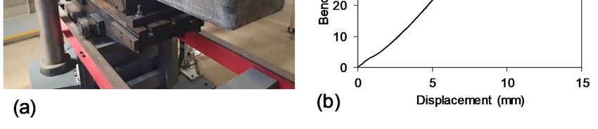
Polymers 2021, 13, 1324                                                                                                     8 of 13

                                   lower than timber. However, the screw pull-out resistance is lower than the minimum
                                   requirement as per AREMA specification for polymer composite sleeper. Therefore, a
                                   further investigation is necessary to overcome the limitations of PU foam core FRP sleeper.
                                   The next section highlighted how to improve screw pull-out resistance without sacrificing
                                   other requirements.

                              Table 4. Performance Comparison of PU Foam Core FRP Sleeper (Concept-1).

                                                                                      AREMA
                 Properties                   Concept-1         Softwood                                      Observation
                                                                                    Requirements
 Density (kg/m3 )                                640               855              Not available         Lighter than timber
 Bending modulus of elasticity (GPa)             5.15              7.4                  1.17                 Satisfactory
 Rail-seat compression modulus (MPa)             450               650              Not available         Lower than timber
 Modulus of rupture (MPa)                         94              22–34                 13.8                 Satisfactory
 Screw pull-out resistance (kN)                  13.2               40                  22.2                Unsatisfactory

                                   3. Overcoming Challenges of Sleeper Concept-1
                                   3.1. Development of PFR Core FRP Sleeper Concept (Concept-2)
                                         The low strength capacity of PU foam core in sleeper Concept-1 is the main issue
                                   identified for low screw holding capacity as no crack was observed on the FRP. Therefore,
                                   the strength properties of core material need to be improved. One approach to improve
                                   the core properties is to use the particulate filled resin (PFR) system. Ferdous et al. and
                                   Khotbehsara et al. [20–22] developed a PFR that has superior strength properties and could
                                   be suitable for manufacturing polymer railway sleepers. However, the PFR is expensive
                                   compared to PU core since the latter one is a foam that can add volume without increasing
                                   cost. Therefore, a minimum volume of PFR should be used to minimise the cost of sleeper.
                                   Since the purpose of introducing PFR is to improve the screw holding capacity, they can
                                   be filled at the rail-seat region only while the other parts of the hollow FRP tube can be
                                   filled with low cost material such as ordinary portland cement (OPC) concrete which is
                                   even cheaper than PU foam core. This approach may increase the overall weight of the
                                   sleeper as both PFR and OPC concrete are heavier than PU core. However, the density of
                                   sleeper Concept-1 is lower than timber (Table 4) and thus a further increase of density may
                                   not create problem. Moreover, it is expected that the density of timber replacement sleeper
                                   should be similar to the density of timber. While lighter sleepers are easy to handle, they
                                   are however less effective to provide lateral stability of the rail-track. A schematic diagram
                                   of the whole concept is provided latter.

                                   3.2. Materials and Manufacturing of Sleeper Concept-2
                                         The 5.2 mm thick FRP tubes used in Concept-2 were fabricated by pultrusion process
                                   and were made of E-glass fibre and vinyl-ester resin with a fibre volume fraction of 60%.
                                   The hollow pultruded section is a preferred choice over the laminates overlapping method
                                   discussed in Concept-1 as the latter one was failed due to skin buckling (Figure 5a). The
                                   PFR in this study was prepared by mixing polyester resin and methyl ethyl ketone peroxide
                                   (MEKP) hardener with a mixing ratio of 100:1.5 g and filled the resin matrix with short
                                   polypropylene (PP) fibres and fly ash fillers. The fillers were mixed together prior to mixing
                                   resin and hardener. Once prepared a homogeneous resin and hardener mix, the mixed
                                   fillers were added to the resin system. The bottom of the FRP tubes were sealed and placed
                                   vertically to fill the tubes from the top end. When tubes were filled with OPC and PFR, the
                                   pouring was done in separate days for each mix. Before testing, the samples were cured in
                                   normal temperature and humidity for more than 28 days.

                                   3.3. Results and Discussion—Performance Evaluation of Sleeper Concept-2
                                   3.3.1. Pull-Out Resistance
                                        Six standard screws were inserted in the PFR core FRP sleeper (Concept-2) as shown
                                   in Figure 7a. The results are plotted in Figure 7b. The first major drop of load for Screw-1,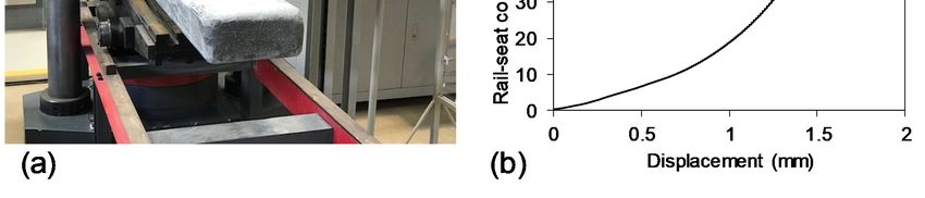
vertically to fill the tubes from the top end. When tubes were filled with OPC and PFR,
the pouring was done in separate days for each mix. Before testing, the samples were
cured in normal temperature and humidity for more than 28 days.
3.3. Results and Discussion—Performance Evaluation of Sleeper Concept-2
Polymers 2021, 13, 1324 9 of 13
3.3.1. Pull-Out Resistance
Six standard screws were inserted in the PFR core FRP sleeper (Concept-2) as shown
in Figure 7a. The results are plotted in Figure 7b. The first major drop of load for Screw-1,
Screw-2
Screw-2 and
and Screw-3
Screw-3 were
were observed
observed at
at 40.47
40.47 kN,
kN, 43.20
43.20 kN
kN and
and 39.81
39.81 kN
kN with
with an
an average
average
of 41.16 kN (standard deviation of 1.8). Only three screws were tested as the ultimate
of 41.16 kN (standard deviation of 1.8). Only three screws were tested as the ultimate
pullout resistance for the first three screws were consistent. It can be seen that the PFR
pullout resistance for the first three screws were consistent. It can be seen that the PFR
core (41.16 kN) in sleeper Concept-2 significantly improved the pull-out resistance when
core (41.16 kN) in sleeper Concept-2 significantly improved the pull-out resistance when
compare to PU foam core (13.2 kN only) in sleeper Concept-1. Moreover, the average screw
compare to PU foam core (13.2 kN only) in sleeper Concept-1. Moreover, the average
holding capacity of PFR core sleeper is very similar to the minimum required capacity for
screw holding capacity of PFR core sleeper is very similar to the minimum required ca-
timber sleepers (40 kN as per AS1085.18 standard). Therefore, PFR core has potential for
pacity for timber sleepers (40 kN as per AS1085.18 standard). Therefore, PFR core has po-
manufacturing polymer railway sleepers.
tential for manufacturing polymer railway sleepers.
60
Screw-1
50 Screw-2
Pull-out force (kN)
Screw-3
40
30
20
10
0
0 2 4 6 8 10
Displacement (mm)
(a) (b)
Figure 7.
Figure 7. Pull-out
Pull-out test
test of
of the
the PFR
PFR core
core FRP
FRP sleeper
sleeper (Concept-2).
(Concept-2). (a)
(a) Pull-out
Pull-out test
test setup.
setup. (b)
(b) Pull-out
Pull-out force
force vs
vs displacement.
displacement.
3.3.2. Effect of the Joint between OPC and PFR
Since the
Since theprimary
primarycomponent
componentofofdrillable
drillablePFR
PFRis is resin,
resin, it more
it is is more expensive
expensive than
than nor-
normal
mal OPC
OPC concrete
concrete whichwhich is non-drillable.
is non-drillable. Therefore,
Therefore, an optimal
an optimal usePFR
use of of PFR
onlyonly at rail-
at rail-seat
seat region
region wherewhere the screws
the screws are drilled
are drilled couldcould significantly
significantly minimise
minimise the of
the cost cost of sleepers.
sleepers. The
The other
other partsparts should
should be filled
be filled with normal
with normal OPC concrete.
OPC concrete. In such In asuch
case,a several
case, several bond
bond areas
between PFR and OPC concrete are obvious which could create weak zones due to the
variation of their elastic modulus properties. To address this concern, one of the two FRP
tubes was filled with PFR and the other one was filled with a combination of normal OPC
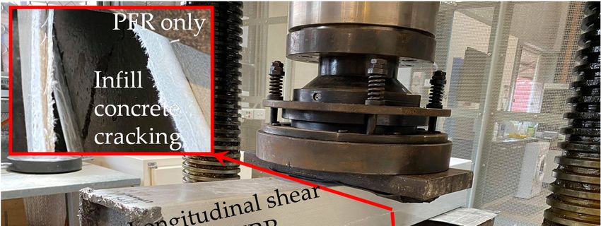
concrete and PFR by equal volume (Figure 8a,b). Centre-point bending test was conducted
to create maximum moment at the bond area as shown in Figure 8b. Both beams were
failed in a similar manner due to the longitudinal shear cracks appeared in FRP tubes
(Figure 8c). The FRP tubes were opened after ultimate failure and it was observed that the
in-fill concrete was cracked at the load point for both beams, particularly the in-fill concrete
in the second beam was failed at the OPC-PFR interface (Figure 8c). However, the joint
between OPC and PFR did not affect the overall behaviour as shown in Figure 8d. The
load-displacement behaviour of both beams were very similar in terms of strength, stiffness
and post-cracking behaviour. This is because the overall behaviour of the beam is governed
by FRP tubes and the type of in-fill materials has less impact due to the confinement
effect. Therefore, it can be said that the PFR is compatible with OPC as in-fill material for
manufacturing polymer railway sleepers.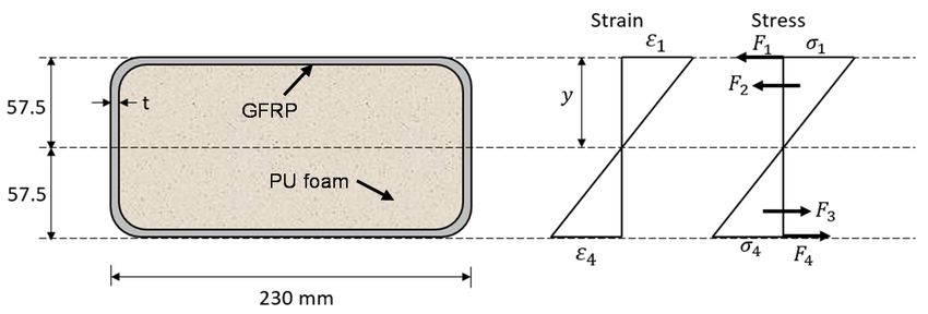
in-fill concrete was cracked at the load point for both beams, particularly the in-fill con-
crete in the second beam was failed at the OPC-PFR interface (Figure 8c). However, the
joint between OPC and PFR did not affect the overall behaviour as shown in Figure 8d.
The load-displacement behaviour of both beams were very similar in terms of strength,
Polymers 2021, 13, 1324
stiffness and post-cracking behaviour. This is because the overall behaviour of the beam
10 of 13
is governed by FRP tubes and the type of in-fill materials has less impact due to the con-
finement effect. Therefore, it can be said that the PFR is compatible with OPC as in-fill
material for manufacturing polymer railway sleepers.
400 mm 400 mm 400 mm 400 mm
PFR PFR OPC PFR
300 mm 300 mm 300 mm 300 mm
(a) (b)
60
50
40
Load, (kN)
30
20
10 Filled with PFR only
Filled with PFR and OPC
0
0 5 10 15
Midspan displacement, (mm)
(c) (d)
Figure
Figure 8. Effect
8. Effect of joint
of joint between
between OPCOPC and
and PFR.
PFR. (a)(a)
FRPFRP tube
tube filled
filled with
with PFR
PFR only.
only. (b)(b)
FRPFRP tube
tube filled
filled withPFR
with PFRand
andOPC.
OPC.(c)
(c) Failure mode. (d) Load-displacement plot.
Failure mode. (d) Load-displacement plot.
3.3.3. Full Length Sleeper Deflection Behaviour
3.3.3. Full Length Sleeper Deflection Behaviour
There still remains the question of how the full-scale sleeper will behave in rail-track.
To There still remains
understand the question
the in-track deflectionofbehaviour
how the full-scale sleeper
of full-scale willa behave
sleeper, five-pointin bending
rail-track.
Totest
understand the in-track deflection behaviour of full-scale sleeper, a five-point
was conducted. The justification of the five-point bending test setup for railway bending
test was conducted. The justification of the five-point bending test setup
sleeper is discussed in [4]. The load was applied until the ultimate failure at 143 kNfor railway sleeper
of
is total
discussed in [4].72The
load (i.e., kNload wasrail-seat).
at each applied until
The the ultimate
specimen wasfailure
failedatdue
143 to
kNtheof total load (i.e.,
longitudinal
72shear
kN atcrack
each in
rail-seat). Theupper
FRP at the specimen
end. was
The failed dueshape
bending to theoflongitudinal
the beam is shear crack
plotted in FRP
in Figure
at 9b.
theItupper end.
can be seen The bending
that shape
a positive of the (sagging
bending beam is plotted
moment) in Figure
occurred9b.atItrail-seat
can be seen that
region
a positive bending (sagging moment) occurred at rail-seat region while negative bending
(hogging moment) observed at mid-span. This is the generalbehaviour observed in real
rail-track condition [23]. The maximum deflection observed at rail-seat location is 5.73 mm
which is larger than the theoretical deflection of 2.66 mm determined in [4]. This is because
a smaller section of 100 × 100 mm instead of the actual sleeper section (230 × 115 mm2 )
was tested to understand whether the concept is suitable for manufacturing sleeper. In this
study, 2.15 times larger (i.e., 5.73/2.66) deflection of the beam than the deflection of the
actual size sleeper is expected as the dimensions of the actual sleeper are 2.3 times wider
(i.e., 230/100) and 1.15 times deeper (i.e., 115/100).
3.4. Findings from Sleeper Concept-2
Sleeper Concept-2 was introduced to overcome the challenge of low screw holding
capacity in sleeper Concept-1. Replacing PU foam core by PFR can significantly improve
and meet the requirements of pull-out resistance for polymer sleepers. Since PFR is an
expensive material, its optimal use is important to minimise the cost of sleepers. Therefore,
the rail-seats region of the FRP tube need to be filled with drillable PFR while other partsPolymers 2021, 13, 1324 11 of 13
can be filled with non-drillable OPC concrete. It was found that the joint between PFR and
OPC concrete does not affect the overall behaviour. Figure 10 proposed the distribution of
infill materials along the sleeper length. Only 600 mm at the two rail-seat locations11need
Polymers 2021, 13, x FOR PEER REVIEW of 13
PFR as an infill material based on the stress distribution pattern described in [9]. This
concept can save almost 50% volume of PFR. Moreover, the FRP tube with a thickness
of 4 mm can provide sufficient strength and stiffness properties. It is estimated that the
while negative bending (hogging moment) observed at mid-span. This is the generalbe-
materials cost of the proposed sleeper concept would be approximately AU$100 per sleeper
haviour observed in real rail-track condition [23]. The maximum deflection observed at
which is quite below than the target final sleeper cost of AU$160 indicated by Queensland
rail-seat location is 5.73 mm which is larger than the theoretical deflection of 2.66 mm
Rail (excluding sleeper reprocessing cost at the end of their life). Although the final product
determined in [4]. This is because a smaller section of 100 × 100 mm instead of the actual
cost of $160 is twice the cost of traditional timber sleeper ($80), however, the life cycle
sleeper section (230 × 115 mm2) was tested to understand whether the concept is suitable
cost of composite sleeper (50 years design life) is expected to be lower than timber sleeper
for manufacturing sleeper. In this study, 2.15 times larger (i.e., 5.73/2.66) deflection of the
(15 years design life). Therefore, manufacturing a high performance and cost effective
beam than the deflection of the actual size sleeper is expected as the dimensions of the
polymer composite railway sleeper is possible using the proposed concept.
actual sleeper are 2.3 times wider (i.e., 230/100) and 1.15 times deeper (i.e., 115/100).
500 mm 1130 mm 500 mm
700 mm 730 mm 500 mm 200 mm
PFR OPC concrete PFR PFR
(a)
Polymers 2021, 13, x FOR PEER REVIEW 12 of 13
the final product cost of $160 is twice the cost of traditional timber sleeper ($80), however,
the life cycle cost of composite sleeper (50 years design life) is expected to be lower than
(b)
timber sleeper (15 years design life). Therefore, manufacturing a high performance and
Figure
Figure 9.
9. Full-scale
Full-scaledeflection behaviour.
cost effective
deflection (a)
(a) Five-point
polymer
behaviour. bending
composite
Five-point (5-PB)
railway
bending test
test setup.
(5-PB)sleeper (b)
(b) Bending
is possible
setup. profile
using
Bending theof
profile sleeper.
proposed
of sleeper. concept.
3.4. Findings From Sleeper Concept-2
Sleeper Concept-2 was introduced to overcome the challenge of low screw holding
capacity in sleeper Concept-1. Replacing PU foam core by PFR can significantly improve
and meet the requirements of pull-out resistance for polymer sleepers. Since PFR is an
expensive material, its optimal use is important to minimise the cost of sleepers. There-
fore, the rail-seats region of the FRP tube need to be filled with drillable PFR while other
parts can be filled with non-drillable OPC concrete. It was found that the joint between
Figure10.
Figure 10.Proposed
Proposedfinal
finaldesign
designofofpolymer
polymersleeper
sleeper(based
(basedononConcept-2).
Concept-2).
PFR and OPC concrete does not affect the overall behaviour. Figure 10 proposed the dis-
tribution of infill materials along the sleeper length. Only 600 mm at the two rail-seat lo-
4. Conclusions
cations need PFR as an infill material based on the stress distribution pattern described in
This
[9]. This study proposed
concept can save aalmost
new concept for manufacturing
50% volume fibre reinforced
of PFR. Moreover, polymer
the FRP tube withrail-
a
way sleeper. The systematic design approach and experimental program identified
thickness of 4 mm can provide sufficient strength and stiffness properties. It is estimated new
materials
that and method
the materials cost offor
thedeveloping composite
proposed sleeper sleeper
concept concept.
would The following
be approximately conclu-
AU$100
sions
per are made:
sleeper which is quite below than the target final sleeper cost of AU$160 indicated byPolymers 2021, 13, 1324 12 of 13
4. Conclusions
This study proposed a new concept for manufacturing fibre reinforced polymer
railway sleeper. The systematic design approach and experimental program identified new
materials and method for developing composite sleeper concept. The following conclusions
are made:
• Filled FRP tube is a promising concept for developing polymer railway sleepers. To
meet the strength and stiffness requirements, a minimum tube thickness of 4 mm is
necessary.
• Polyurethane foam as an infill material can provide sufficient bending and compres-
sion properties. However, it cannot provide sufficient resistance to hold screws.
• Particulate filled resin (PFR) system as an infill material can overcome the limitation
of low screw holding capacity that was observed in polyurethane foam.
• The expensive and drillable infill PFR material can be replaced by the inexpensive and
non-drillable OPC concrete except rail-seat locations.
• The joint between PFR and OPC concrete does not affect the overall performance of
the sleeper as the behaviour of the sleeper is governed by an external FRP tube and
the type of in-fill materials have only minimal impact due to the confinement effect.
• The proposed design of sleeper only requires 50% volume of PFR as infill material that
lead to manufacture a high performance and cost effective railway sleeper technology.
Railway sleepers are often subjected to impact and fatigue loading due to flat wheel
and repeated movements of the train. Therefore, an in-depth understanding of the impact
and fatigue behaviour of the polymer sleeper will ensure its suitability to replace existing
timber sleepers. To understand the fatigue behaviour of a polymer sleeper, the author
attempted to investigate the fatigue behaviour of GFRP laminates [24,25].
Author Contributions: W.F.: conceptualization, methodology, data curation, formal analysis, inves-
tigation, writing—original draft preparation; A.M.: supervision, writing—review & editing; C.S.:
writing—review & editing; P.Y.: writing—review & editing; R.A.: methodology; T.H.: writing—
review & editing; P.S.: supervision. All authors have read and agreed to the published version of the
manuscript.
Funding: This research was funded through Cooperative Research Centres Projects, grant number
[CRC-P57360-CRC-P Round 3] and The APC was waived by MDPI.
Institutional Review Board Statement: Not applicable.
Informed Consent Statement: Not applicable.
Data Availability Statement: Not applicable.
Acknowledgments: This study is supported by the Cooperative Research Centres Projects (CRC-
P57360-CRC-P Round 3) grant.
Conflicts of Interest: The authors declare no conflict of interest.
References
1. Manalo, A.; Aravinthan, T.; Karunasena, W.; Ticoalu, A. A review of alternative materials for replacing existing timber sleepers.
Compos. Struct. 2010, 92, 603–611. [CrossRef]
2. Ferdous, W.; Manalo, A. Failures of mainline railway sleepers and suggested remedies—Review of current practice. Eng. Fail.
Anal. 2014, 44, 17–35. [CrossRef]
3. Bednarczyk, A. New composite sleeper set to undergo live trials. Int. Railw. J. 2019.
4. Ferdous, W.; Manalo, A.; AlAjarmeh, O.; Mohammed, A.A.; Salih, C.; Yu, P.; Khotbehsara, M.M.; Schubel, P. Static behaviour of
glass fibre reinforced novel composite sleepers for mainline railway track. Eng. Struct. 2021, 229, 111627. [CrossRef]
5. Koller, G. FFU synthetic sleeper—Projects in Europe. Constr. Build. Mater. 2015, 92, 43–50. [CrossRef]
6. Kaewunruen, S. Acoustic and dynamic characteristics of a complex urban turnout using fibre-reinforced foamed urethane (FFU)
bearers. In Proceedings of the 11th International Workshop on Railway Noise, Uddevalla, Sweden, 9–13 September 2013.
7. Sengsri, P.; Ngamkhanong, C.; De Melo, A.L.O.; Papaelias, M.; Kaewunruen, S. Damage detection in fiber-reinforced foamed
urethane composite railway bearers using acoustic emissions. Infrastructures 2020, 5, 50. [CrossRef]Polymers 2021, 13, 1324 13 of 13
8. Van Erp, G.; Mckay, M. Recent Australian developments in fibre composite railway sleepers. Electron. J. Struct. Eng. 2013, 13,
62–66.
9. Ferdous, W.; Manalo, A.; Van Erp, G.; Aravinthan, T.; Ghabraie, K. Evaluation of an innovative composite railway sleeper for a
narrow-gauge track under static load. J. Compos. Constr. 2018, 22, 1–13. [CrossRef]
10. Ferdous, W.; Manalo, A.; Van Erp, G.; Aravinthan, T.; Kaewunruen, S.; Remennikov, A. Composite railway sleepers—Recent
developments, challenges and future prospects. Compos. Struct. 2015, 134, 158–168. [CrossRef]
11. Gill, B.; Woodgate, C.; Smith, G. Material Supply Specification (Track-CT.172)—Alternative Sleepers; Queensland Rail: Brisbane,
Australia, 2015.
12. Loos, M. Carbon Nanotube Reinforced Composites: CNT Polymer Science and Technology; Elsevier: London, UK, 2014.
13. Ferdous, W.; Manalo, A.; Khennane, A.; Kayali, O. Geopolymer concrete-filled pultruded composite beams–concrete mix design
and application. Cem. Concr. Compos. 2015, 58, 1–13. [CrossRef]
14. Manalo, A.; Aravinthan, T.; Karunasena, W.; Stevens, N. Analysis of a typical railway turnout sleeper system using grillage beam
analogy. Finite Elem. Anal. Des. 2012, 48, 1376–1391. [CrossRef]
15. Park, K.-B.; Kim, H.-T.; Her, N.-Y.; Lee, J.-M. Variation of mechanical characteristics of polyurethane foam: Effect of test method.
Materials 2019, 12, 2672. [CrossRef] [PubMed]
16. AREMA. Manual for Railway Engineering, Chapter 30: Ties; American Railway Engineering and Maintenance-of-way Association:
Lanham, MD, USA, 2013.
17. Ferdous, W.; Aravinthan, T.; Manalo, A.; Van Erp, G. Composite railway sleepers: New developments and opportunities. In
Proceedings of the 11th International Heavy Haul Association Conference, Perth, Australia, 21–24 June 2015.
18. RISSB. Call for Public Consultation—AS 1085.22 Railway Track Materials: Alternative Material Sleepers; Rail Industry Safety and
Standards Board: Brisbane, Australia, 2019.
19. Standards-Australia. AS 1085.18: Railway Track Material—Screw Spikes and Threaded Inserts; Standards-Australia: Sydney, Australia,
2013.
20. Ferdous, W.; Manalo, A.; Aravinthan, T.; Van Erp, G. Properties of epoxy polymer concrete matrix: Effect of resin-to-filler ratio
and determination of optimal mix for composite railway sleepers. Constr. Build. Mater. 2016, 124, 287–300. [CrossRef]
21. Khotbehsara, M.M.; Manalo, A.; Aravinthan, T.; Ferdous, W.; Nguyen, K.T.; Hota, G. Ageing of particulate-filled epoxy resin
under hygrothermal conditions. Constr. Build. Mater. 2020, 249, 118846. [CrossRef]
22. Khotbehsara, M.M.; Manalo, A.; Aravinthan, T.; Turner, J.; Ferdous, W.; Hota, G. Effects of ultraviolet solar radiation on the
properties of particulate-filled epoxy based polymer coating. Polym. Degrad. Stab. 2020, 181, 109352. [CrossRef]
23. Jeffs, T.; Tew, G.P. A Review of Track Design Procedures; BHP Research-Melbourne Laboratories: Melbourne, Australia, 1991.
24. Ferdous, W.; Manalo, A.; Peauril, J.; Salih, C.; Reddy, K.R.; Yu, P.; Schubel, P.; Heyer, T. Testing and modelling the fatigue
behaviour of GFRP composites–Effect of stress level, stress concentration and frequency. Eng. Sci. Technol. Int. J. 2020, 23,
1223–1232. [CrossRef]
25. Ferdous, W.; Manalo, A.; Yu, P.; Salih, C.; Abousnina, R.; Heyer, T.; Schubel, P. Tensile fatigue behavior of polyester and vinyl
ester based GFRP laminates—A comparative evaluation. Polymers 2021, 13, 386. [CrossRef] [PubMed]You can also read