Betelgeuse scope: Single-mode-fibers-assisted optical interferometer design for dedicated stellar activity monitoring - export.arXiv.org
←
→
Page content transcription
If your browser does not render page correctly, please read the page content below
Betelgeuse scope: Single-mode-fibers-assisted optical
                                              interferometer design for dedicated stellar activity monitoring
                                              Narsireddy Anugua , Katie M. Morzinskia , Josh Eisnera , Ewan Douglasa , Dan Marronea , Steve
                                               Ertela , Sebastiaan Hafferta , Oscar Montoyaa , Jordan Stonea , Stefan Krausb , John Monnierc ,
                                                Jean-Baptiste Lebouquind , Jean-Philippe Bergerd , Julien Woilleze , and Miguel Montargèsf
                                                    a
                                                        Steward Observatory, Department of Astronomy, University of Arizona, Tucson, USA
                                              b
                                                  School of Physics and Astronomy, University of Exeter, Exeter, Stocker Road, EX4 4QL, UK
arXiv:2010.04243v1 [astro-ph.IM] 8 Oct 2020

                                                                         c
                                                                           University of Michigan, Ann Arbor, MI 48109, USA
                                                         d
                                                           Institut de Planetologie et d’Astrophysique de Grenoble, Grenoble 38058, France
                                                   e
                                                     European Southern Observatory, Karl-Schwarzschild-Straße 2, 85748 Garching, Germany
                                                    f
                                                      Institute of Astronomy, KU Leuven, Celestijnenlaan 200D B2401, 3001 Leuven, Belgium

                                                                                                ABSTRACT
                                              Betelgeuse has gone through a sudden shift in its brightness and dimmed mysteriously. This is likely caused
                                              by a hot blob of plasma ejected from Betelgeuse and then cooled to obscuring dust. If true, it is a remarkable
                                              opportunity to directly witness the formation of dust around a red supergiant star. Today’s optical telescope
                                              facilities are not optimized for time-evolution monitoring of the Betelgeuse surface, so in this work, we propose
                                              a low-cost optical interferometer. The facility will consist of 12 × 4 inch optical telescopes mounted on the
                                              surface of a large radio dish for interferometric imaging; polarization-maintaining single-mode fibers will carry
                                              the coherent beams from the individual optical telescopes to an all-in-one beam combiner. A fast steering mirror
                                              assisted fiber injection system guides the flux into fibers. A metrology system senses vibration-induced piston
                                              errors in optical fibers, and these errors are corrected using fast-steering delay lines. We will present the design.

                                                                                          1. INTRODUCTION
                                              The bright red supergiant star (RSG), Betelgeuse, is experienced a sudden shift in the brightness in 2019-2020 and
                                              has been the subject of much debate. The visual dimming started in 2019 November and reaching a historical
                                              minimum (1.614 ± 0.008 magnitude) of only 37% of its average brightness on 2020 February 10 (see Fig. 1).
                                              Subsequently, the optical magnitude began to recover until the end of 2020 May then started dimming again.
                                              These unexpected Great Dimming events pose several questions about its future as it also skipped its normal
                                              pulsation cycle of ∼ 420 days: (i) Has it entered a new phase of very frequent dimming events? (ii) Being a
                                              candidate to become a core-collapse Type II supernova has entered into the pre-supernovae phase?
                                                   Observations from various facilities suggest broadly two hypotheses (i) formation of dark spots on its surface,
                                              (ii) formation of dust close to the star and blocking light in our line of sight:

                                                   • Dark spots hypothesis: Submillimeter observations taken by the James Clerk Maxwell Telescope and
                                                     Atacama Pathfinder Experiment have claimed that the presence of dark spot(s).1

                                                   • Dust formation and blocking hypothesis: The spectrophotometric2 and high spectral resolution3
                                                     observations recorded during the Great Dimming event do not report any notable changes in its effective
                                                     temperature (∼ 3600 K) or emission lines [Fe II] and [S I] in comparison to past non-dimming observations.
                                                     Differential speckle polarimetry observations show that the polarized flux of the circumstellar envelope
                                                     around the star is increased after the dimming event (2020 February 10) but remains constant before or
                                                     during the Great Dimming – indicating dust formation.4
                                                   E-mail: nanugu@arizona.edu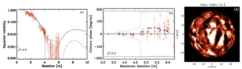
VLT/SPHERE adaptive optics visible polarimetric images5 have shown that the star shape has changed
      significantly in the Southern Hemisphere and revealed a substantial dimming of the star favoring dust
      blocking in the line of sight.
      Spatially resolved ultraviolet spectra using the Hubble Space Telescope/Space Telescope Imaging Spectro-
      graph suggest a hot blob of plasma is ejected from the activity of huge convection cells on the Betelgeuse’s
      surface. This plasma is then cooled to form an enormous cloud of obscuring dust around the Southern
      hemisphere of star.6
      All these observations suggest mass ejection from the known large convective cells in the photosphere and
      then cooled to form the dust cloud in the southern hemisphere in our line of sight.

    The hypotheses mentioned above insist on high-angular observations of the Betelgeuse photosphere and,
importantly, time-evolution monitoring as it entered into a new phase. If the dust-formation-and-blocking theory
is correct, this event is a remarkable opportunity to directly witness the formation of dust around a red supergiant
star. Where the red supergiant stars are essential contributors to the chemical enrichment of the universe, the
mass-loss phase in their evolution is not well understood. High angular resolution monitoring of the Betelgeuse
surface is crucial to spatially probe the photospheric convection and ultimately reveal the mysterious mass-loss
processes. Such a program would require a regular – at least once per week – a survey of the star’s photosphere
and circumstellar environment.
    Betelgeuse’s angular size is ∼ 43 mas.7, 8 Unfortunately, no single, currently operating facility is optimized for
such a time-evolution monitoring campaign. The interferometric facilities, COAST9 and IOTA,7 used as machines
of Betelgeuse surface imaging have been retired. Existing monolithic 8-m class apertures, such as LBT, barely
resolve the Betelgeuse diameter and thus cannot resolve its convection cells. On the other hand, long-baseline
interferometers (ex. existing CHARA,10 VLTI,11 NPOI,12 and future MROI13 ) can resolve the convection cells
using its long baselines but suffer from the lack of short baselines, which are essentially needed for detailed
image reconstruction.14 The combination of non-redundant masking (NRM) from 8-m class telescopes and
long-baseline interferometric observations can prove efficient for the best imaging reconstruction. NRM allows
imaging of the outer-scale overall object shape and while the long-baseline interferometry observations provide
complimentary inner-scale convection cell information. However, a tight, extensive, collaborative scheduling
between observatories is required for this task is a realistically unfeasible, and regular interval of monitoring
observations is very expensive.
   Adaptive optics observations of future > 30 m class facilities such as E-ELT and TMT can image the
Betelgeuse convection cells with 5 pixels across the stellar diameter in J-band. Implementation of non-redundant
aperture masking for the first light instruments of E-ELT is being investigated (ex. E-ELT/METIS). However,
they will be ready only after 2025, and monitoring observations will be costly. Doppler imaging technique
observations are limited in determining the longitude location of convection cells.15
   Therefore, in this work, we propose a novel, low-cost, 12×4 inch telescopes based optical interferometer design
mounted on a maximum baseline B = 12 m radio dish. This concept can image the surface of Betelgeuse with
λ/2B ≈ 5 mas angular resolution with ≈ 8 pixels across the stellar diameter in the R-band (λ = 630 − 780 nm).
It will deliver observations of the time-evolution of Betelgeuse’s convection cells every night and reveal the
phenomena which cause the mass-loss process.

        2. HISTORICAL HIGH-ANGULAR OBSERVATIONS OF BETELGEUSE
Betelgeuse’s large angular size (∼ 43 mas) and brightness (R-band apparent magnitude ∼ -1) make it a prime
target for the red supergiant mass-loss studies. Betelgeuse has been the subject of many studies over the past
century, starting from the first angular diameter measurement by Michelson & Peace in 1920, exactly a century
ago.16 An appropriate historical background of the optical interferometry and recent state-of-the-art of the
field can be found elsewhere.14 An asymmetric and multi-feature circumstellar environment of Betelgeuse is
detected with infrared wavelength observations using lucky imaging.17 Recently, its convective activity has been
imaged utilizing COAST, IOTA and VLTI optical interferometers7–9 and spectropolarimetric measurements.18
Advanced numerical hydrodynamic simulations19 were conducted and they predict convection cells of various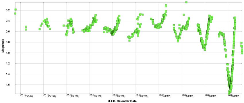
Figure 1. AAVSO visible light curve of Betelgeuse in V bands in the last ten years. In 2019 November, the star’s brightness
in the V magnitude started to fall below its average value. On 2020 February 10, Betelgeuse reached a historical minimum
(1.614 ± 0.008) of more than a magnitude dimmer than its average value. At the end of this Great Dimming, Betelgeuse
started brightening from 2020 February 10 until the end of 2020 May and since then started dimming again and continuing
(last data point 2020 August 15).

sizes in contrast to observation detected large convection cells.7–9 Multi-epoch high-angular observations of
Betelgeuse photosphere is required to constrain the convection cell size and intensity contrast in the models.

                                    3. BETELGEUSE SCOPE DESIGN
3.1 Concept
We propose a new facility Betelgeuse scope consists of 12 × 4 inch optical Cassegrain telescopes array mounted
to the surface of a large radio dish. Polarization-maintaining single-mode fibers will carry the coherent beams
from the individual optical telescopes to the central beam combining the facility at the control cabin of the
radio dish. An all-in-one beam combiner14 (similar to CHARA/MIRC-X20 ) will be implemented, and this will
allow model-independent aperture synthesis image of Betelgeuse with ∼8 resolution pixels across the Betelgeuse
diameter in the R-band (630 – 780 nm) with interferometric angular resolution of λ/2B ≈ 5 mas. The radio
dish concept is chosen as it relaxes the cost of long delay lines and also the pointing and tracking control for
the individual optical telescopes by having a common mount. This is a significant cost-saving concept; most of
the interferometer cost goes for the delay lines and the pointing and tracking control of individual telescopes.
Our observing strategy is to point at only one target, Betelgeuse, the entire possible night, increasing the (u,v)
coverage using the Earth’s rotation. The benefit of this common mount is that we don’t need longer delay lines
as in for the traditional non-common mount based long-baseline interferometers, which have to compensate for
the changing geometrical delay between wavefronts reaching any two telescopes.
    The pointing and tracking errors (∼ 2 arcsec) of mm-wave radio dish are similar to those of optical telescopes.21
We are prepared for technical challenges from atmospheric turbulence, vibrations, and pointing errors from the
radio dish in the practical windy conditions. These errors cause difficulties22, 23 related to the flux injection into
single-mode fibers as well as vibration-induced fiber piston errors. Capitalizing on the fact that Beletgeuse is
very bright in R-band (magnitude ∼ -1), the flux injection into fibers will be maximized using a standard tip-tilt
correction with a fast steering mirror and a fast frame rate detector operated in V -band. The vibration-induced
fiber piston errors will be measured using a state-of-the-art metrology system. It works by sending a coherent
laser beam into the single-mode fibers from the beam combiner side and back-reflecting the beam from the
telescope side for recording metrology fringes on the same science camera. The metrology laser will measure
the instrumental vibration-related piston errors, and the science beam will measure atmospheric piston errors.
Piezo-actuated pathlength correctors with a resolution of a micron and a centimeter range will correct both
these error sources. The astronomical science measurements will be conducted in the R-band, and the metrology
system will work at a different wavelength (in I-band).
We will use group delay fringe tracking14, 20 enabled by dispersing the fringes. High-spectral resolution (R ∼
10000) observations will be recorded to allow detection of turbulent motion in the atmosphere by measuring the
velocity of the gas at each position.24
The R-band filter has been chosen as it offers the following advantages.
1. R-band offers a higher angular resolution than near-infrared wavelengths and is important astrophysically
as the dimming is happening in these wavelengths. See Fig. 3, for expected visibilities.
2. Detectors, which have a fast frame rate, low-readout-noise, and large size, are relatively inexpensive at
R-band wavelengths. The fringes of all 12 telescopes (66 baselines) will be recorded on 1024 pixels along
the spatial direction and 8 pixels (lowest dispersion mode) along the spectral direction (See Fig. 2 for the
optical layout). We need the detector with fast frame rates to take short-exposures within the atmospheric
coherence time, ∼ 500 Hz. A low-readout-noise enables high-spectral resolution observations, dispersing
the light over many pixels. For this 1608×1104 pixels based C-BLUE ONE camera from First-light-imaging
can be a good choice with 660 Hz full window frame rate (for sub-window 1024 × 8 pixels readouts the
frame rates even higher), < 3e− readout noise and 70% quantum efficiency at R-band.
3. R-band is a trade-off wavelength considering sensitivity of Betelgeuse (brighter in near-infrared J = −3
than R = −1) and atmospheric coherence time (τ (λ) ∝ λ6/5 at most sites it is ∼ 10 ms at λ = 500 nm).
Typical atmospheric coherence radius, the Fried parameter r0 (λ) ∝ λ6/5 , at R-band is approximately equal
to 4-inch, so choosing a D = 4 inch for the individual telescope size does not require adaptive optics. With
a closed-loop tip-tilt correction assisted fiber injection, we estimate to achieve better than 1% effective
throughput, with that we get 250 signal-to-noise ratio at 1 ms coherent integration.
We will use single-mode fibers to spatially filter the atmospheric distorted wavefronts to enable stable visibility
and closure phase measurements.25 In the visible wavelengths, differential chromatic dispersion is usually large
in magnitude if the optical path is not in a vacuum. To compensate this effect, longitudinal dispersion correction
systems are built.10 However, we expect no substantial differential chromatic dispersion for the Betelgeuse scope
as a tiny path of light is propagating in the air, so we don’t require a longitudinal dispersion correction system.
We will use polarization maintaining fibers to maximize the maximum visibility contrast. We will use the same set
of light-collecting and fiber injection optics to minimize the polarization differences between individual telescopes
to maximize visibility contrast. All the lengths of fibers will be matched closely. If any mismatch in the lengths
introduces birefringence, and that can lead to loss of fringe contrast.20
The Van Cittert-Zernike Theorem relates the source brightness distribution to the contrast of an interferom-
eter’s fringes to a unique Fourier frequency.14 The basic interferometric observables are the visibility and closure
phase. Visibility is a measure of the spatial resolution of the source by a given baseline at a given wavelength.
The raw visibility is calibrated using calibrator stars with known diameter. The closure phases are related to the
asymmetry of source – the closure phase is null for a centrosymmetric target. The closure phase is, in principle,
a self-calibrated measure. With the N = 12 telescope interferometer we get N (N2−1) = 66 independent visibility
and closure phase measurements.
Ring interferometric configuration is chosen to install the optical telescopes on the edge of the radio dish,
which will not interfere with any regular radio observations (Fig. 2). The non-redundant baseline separation
decides fringe spatial frequencies of all baselines u = B/λ radians−1 . As aforementioned, the visibility of long-
baseline fringes is low in comparison to small baseline fringes. The baselines selection will be made considering
Betelgeuse’s diameter so that its visibilities do not fall in the zero nulls (Fig. 3). A baseline bootstrapping
method based on nearest pairs will be used, in order to track the most resolved baselines efficiently.14
Model-independent image reconstruction in the optical interferometry and especially imaging the surface of
stars is matured now,26, 27 with several image reconstruction tools readily available to use, for example, macim,28
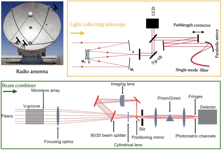
squeeze29 and MiRA.30Figure 2. Cartoon showing the pathfinder Betelgeuse scope concept. Top left: three non-redundant telescope array to be installed on a 6-m radio dish. Yellow box (top right) shows the layout for optical telescope light collection, tip-tilt, and pathlength corrections and fiber light injection at the telescope site. Green box (bottom) shows the layout for the beam combiner instrument, which combines the beams from fibers and makes interferometric fringes. A similar design of CHARA/MIRC-X will be used for the three beam pathfinder Betelgeuse scope.20 Once the telescope beams injected into fibers, they are arranged in a V-groove non-redundantly to allow various spatial frequency fringes. The beams are combined at the focus of the lens in the “all-in-one” beam combining scheme, and fringes are made. A cylindrical lens compresses the fringe pattern in the spectral direction, and then a prism disperses the light in the perpendicular direction to the spatial direction of fringes. Photometric channels are made with a beam splitter (20 flux split). Figure 3. The visibility curves are plotted in left column, while the closure phases are shown in central column. The right image is the Betelgeuse synthetic image matched the observation data from Young et al. 2004 from the COAST interferometer. The figure is reproduced from Chiavassa et al. (2010).19
3.2 Advancements to the field
Betelgeuse scope offers the following advancements to the field.

   • The intellectual merit of the project derives from its potential of observing the time-evolution of Betelgeuse’s
     convection cells every night and correlate them to mass-loss phenomena. In the second half of the year,
     when Betelgeuse is not observable, the scope will observe the second brightest RSG star, Antares (diameter
     ∼ 37 mas; R-band mag ∼ -0.65). This target is also interesting astrophysically, where a previous study24
     suggests its convection alone cannot explain the observed turbulent motions. Betelgeuse scope is also
     optimized to make observations of very interesting large size symbiotic systems such as R Aqr.31 In R Aqr
     system, the dwarf, disk, and cloud move in a 44-year orbit around the system’s center of mass. The next
     eclipse is expected to begin in 2021 and continue until 2024.
   • The modular aspect of the instrument is that it can be extended to several telescopes array to increase the
     (u,v)-coverage for better and faster image reconstruction.
   • The technology demonstration in this proposed project may have significant broader impacts for the future
     of long-baseline interferometry in using inexpensive optical fibers for light transport. Currently, building
     kilometer size optical interferometers are limited due to the high cost of vacuum pipes for light transport.
     Furthermore, small-satellite-enabled interferometric projects may benefit as their size and weight need to
     be small, where fiber usage helps in place of several mirrors for light transport.

3.3 Pathfinder on 6-m radio dish
We are building a pathfinder for a 6-m radio dish owned by the University of Arizona. We have procured one set
(out of 12) of light collecting and fiber injection optics and integrating them in our lab at Steward Observatory,
Arizona. We need an efficient fiber light injection system as it is the only limitation for throughput. Note this
design has a very few mirror light reflections involved.
   The selection of light collecting and fiber injection hardware is a trade-off in between (i) low-cost-budget
requirement and (ii) meeting specifications to maximize flux injection into fibers.

Telescope: A smaller tube telescope is preferred for mechanical constraints. A 4 inch telescope from Orion
Apex Maksutov-Cassegrain is computed to have a signal-to-noise ratio of 250 at 1 ms integration with an effective
throughput of 1%.

Tip-tilt actuator: Speed and large stroke is the requirement to correct large amplitude vibrations or atmo-
spheric tip-tilts. 1-inch mirror from the optics in motion company, OIM101 is selected as it operates at 550 Hz
speed (3dB Bandwidth), allows large tip-tilt stroke ±1.5◦ , with excellent tip-tilt resolution < 2µrad and with
good wavefront quality λ/10 at 633 nm.

Tip-tilt tracking camera: A large field of CMOS camera is the requirement to detect large amplitude vi-
brations or atmospheric tip-tilt based offsets. FLIR BFS-PGE-04S2M-CS CMOS camera is selected, which has
720 × 540 pixels with a pixel size of 6.9 µm, operates at full-frame readout at 291 Hz (appropriate ROI will be
used) and have quantum efficiency 65% at R-band. It is a GigE camera, and the frame grabbing is done with
Ethernet communication.

Fiber collimator and fiber selection: Polarization, maintaining single-mode fibers are the requirements
to minimize birefringence to allow maximum instrumental visibility contrast. Since we aim to record fringes
in narrow-bandwidth filter off-axis parabola based fiber coupling is not the main requirement. We selected a
readily available Thorlabs air-spaced doublet fiber collimator. Polarization maintained single-mode fibers (Nufern
PM-S630-HP, single-mode 630 – 780 nm).
Real-time control software: In total, two active control loops run during the observations:
1. Tip-tilt tracking to maximize flux injection into single-mode fibers.
2. Fringe tracking to measure OPD offsets caused by the atmosphere at science wavelengths and OPD offsets
caused by the telescope and instrument vibrations at metrology wavelengths.
We are developing the tip-tilt tracking software consists of following software modules:
1. Reading frames from the tip-tilt tracking camera
2. Computing the tip-tilt offsets
3. Guiding the tip-tilt actuator for an efficient flux injection into the fiber
For the real-time software, we have adapted CHARA Array software architecture:10 (i) C-written servers to
communicate with hardware and (ii) C-written GNOME Tool Kit (GTK) based Graphical User Interface (GUI)
clients to communicate with the servers during the observations. We will adapt CHARA/MIRC-X real-time
control software for data processing and group delay tracking and data recording sequences.20, 32 We will adapt
already tested and used 6-telescope CHARA/MIRC-X data reduction pipeline written in python.20
We are delayed by the COVID-19 pandemic and anticipate to install this light collecting optics in 2020
September and test the throughput into the fibers. We expect installing the three-beam combiner once the tests
finished. For the beam combiner, we will use CCD-39 camera (80 × 80 pixels with each 24 µm, readout noise
7e− /px, frame rate > 1 KHz) from the Steward LBTI lab.
Fig. 3 shows the expected visibilities, closure phases for B = 6 m and also a data matched synthetic image
match similar baselines of Betelgeuse scope in the R-band.
4. CONCLUSION
Betelgeuse is a red supergiant star and candidate to become a core-collapse Type II supernova. The Great
Dimming of Betelgeuse attracted enormous public attention. Betelgeuse convection cell activity thought is a
reason for this dimming by forming a clump of dust in our line of sight. High angular resolution measurements are
crucial to spatially probe the photospheric convection and ultimately reveal the mysterious mass-loss processes.
A dedicated interferometric facility such as the proposed Betelgeuse scope with 12 × 4 telescopes resulted in
66 visibilities, and 66 independent closure phases allows taking snapshot images of convection cells and time-
evolution monitoring. This is a design leveraging advances in the recent optical interferometry field and in
the telecommunication industry for astronomy. Our efforts for building a prototype on a 6-m radio dish are
underway, and we anticipate installing it at the end of 2020.
5. ACKNOWLEDGMENTS
Anugu acknowledges support from the Steward Observatory Fellowship in Instrumentation and Technology
Development. We thank you the variable star observations from the AAVSO International Database contributed
by observers worldwide and used in this research.
REFERENCES
[1] Dharmawardena, T. E., Mairs, S., Scicluna, P., Bell, G., McDonald, I., Menten, K., Weiss, A., and Zijlstra,
A., “Betelgeuse Fainter in the Submillimeter Too: An Analysis of JCMT and APEX Monitoring during the
Recent Optical Minimum,” Astrophys. J. letters 897(1), L9 (2020).
[2] Levesque, E. M. and Massey, P., “Betelgeuse Just Is Not That Cool: Effective Temperature Alone Cannot
Explain the Recent Dimming of Betelgeuse,” Astrophys. J. letters 891(2), L37 (2020).[3] Harper, G. M., DeWitt, C. N., Richter, M. J., Guinan, E. F., Wasatonic, R., Ryde, N., Montiel, E. J.,
and Townsend, A. J., “SOFIA-EXES Observations of Betelgeuse during the Great Dimming of 2019/2020,”
Astrophys. J. letters 893(1), L23 (2020).
[4] Safonov, B., Dodin, A., Burlak, M., Goliguzova, M., Fedoteva, A., Zheltoukhov, S., Lamzin, S., Strakhov,
I., and Voziakova, O., “Differential Speckle Polarimetry of Betelgeuse in 2019-2020: the rise is different from
the fall,” arXiv e-prints , arXiv:2005.05215 (2020).
[5] Montargès, M., “ESO Telescope Sees Surface of Dim Betelgeuse.” ESO, 4 February 2020 https://www.
eso.org/public/news/eso2003/. (Accessed: 15 August 2020).
[6] Dupree, A. K., Strassmeier, K. G., Matthews, L. D., Uitenbroek, H., Calderwood, T., Granzer, T., Guinan,
E. F., Leike, R., Montargès, M., Richards, A. M. S., Wasatonic, R., and Weber, M., “Spatially Resolved
Ultraviolet Spectroscopy of the Great Dimming of Betelgeuse,” arXiv e-prints , arXiv:2008.04945 (2020).
[7] Haubois, X., Perrin, G., Lacour, S., Verhoelst, T., Meimon, S., Mugnier, L., Thiébaut, E., Berger, J. P.,
Ridgway, S. T., Monnier, J. D., Millan-Gabet, R., and Traub, W., “Imaging the spotty surface of Betelgeuse
in the H band,” Astron. Astrophys. 508(2), 923–932 (2009).
[8] Montargès, M., Kervella, P., Perrin, G., Chiavassa, A., Le Bouquin, J. B., Aurière, M., López Ariste, A.,
Mathias, P., Ridgway, S. T., Lacour, S., Haubois, X., and Berger, J. P., “The close circumstellar environment
of Betelgeuse. IV. VLTI/PIONIER interferometric monitoring of the photosphere,” Astron. Astrophys. 588,
A130 (2016).
[9] Young, J. S., Baldwin, J. E., Boysen, R. C., Haniff, C. A., Lawson, P. R., Mackay, C. D., Pearson, D.,
Rogers, J., St. -Jacques, D., Warner, P. J., Wilson, D. M. A., and Wilson, R. W., “New views of Betelgeuse:
multi-wavelength surface imaging and implications for models of hotspot generation,” Mon. Not. R. Astron.
Soc. 315(3), 635–645 (2000).
[10] ten Brummelaar, T. A., McAlister, H. A., Ridgway, S. T., Bagnuolo, W. G., J., Turner, N. H., Sturmann,
L., Sturmann, J., Berger, D. H., Ogden, C. E., Cadman, R., Hartkopf, W. I., Hopper, C. H., and Shure,
M. A., “First Results from the CHARA Array. II. A Description of the Instrument,” Astrophys. J. 628(1),
453–465 (2005).
[11] Haguenauer, P., Abuter, R., Andolfato, L., Alonso, J., Blanchard, G., Berger, J.-P., Bourget, P., Brillant,
S., Derie, F., Delplancke, F., Di Lieto, N., Dupuy, C., Gilli, B., Gitton, P., Gonzalez, J. C., Guisard, S.,
Guniat, S., Hudepohl, G., Kaufer, A., Lévêque, S., Ménardi, S., Mérand, A., Morel, S., Percheron, I., Phan
Duc, T., Poupar, S., Ramirez, A., Reineiro, C., Rengaswamy, S., Rivinius, T., Schöller, M., Schmid, C.,
Segovia, A., Schuhler, N., Valdes, G., de Wit, W. J., and Wittkowski, M., “The Very Large Telescope
Interferometer v2012+,” Proc. SPIE 8445, 84450D (2012).
[12] Armstrong, J. T., Mozurkewich, D., Rickard, L. J., Hutter, D. J., Benson, J. A., Bowers, P. F., Elias, N. M.,
I., Hummel, C. A., Johnston, K. J., Buscher, D. F., Clark, J. H., I., Ha, L., Ling, L. C., White, N. M., and
Simon, R. S., “The Navy Prototype Optical Interferometer,” Astrophys. J. 496(1), 550–571 (1998).
[13] Buscher, D. F., Creech-Eakman, M., Farris, A., Haniff, C. A., and Young, J. S., “The Conceptual Design of
the Magdalena Ridge Observatory Interferometer,” Journal of Astronomical Instrumentation 2(2), 1340001
(2013).
[14] Monnier, J. D., “Optical interferometry in astronomy,” Reports on Progress in Physics 66(5), 789–857
(2003).
[15] Roettenbacher, R. M., Monnier, J. D., Korhonen, H., Harmon, R. O., Baron, F., Hackman, T., Henry, G. W.,
Schaefer, G. H., Strassmeier, K. G., Weber, M., and ten Brummelaar, T. A., “Contemporaneous Imaging
Comparisons of the Spotted Giant σ Geminorum Using Interferometric, Spectroscopic, and Photometric
Data,” Astrophysics J. 849(2), 120 (2017).
[16] Michelson, A. A. and Pease, F. G., “Measurement of the Diameter of α Orionis with the Interferometer.,”
Astrophys. J. 53, 249–259 (1921).
[17] Kervella, P., Perrin, G., Chiavassa, A., Ridgway, S. T., Cami, J., Haubois, X., and Verhoelst, T., “The close
circumstellar environment of Betelgeuse. II. Diffraction-limited spectro-imaging from 7.76 to 19.50 µm with
VLT/VISIR,” Astron. Astrophys. 531, A117 (2011).
[18] López Ariste, A., Mathias, P., Tessore, B., Lèbre, A., Aurière, M., Petit, P., Ikhenache, N., Josselin,
E., Morin, J., and Montargès, M., “Convective cells in Betelgeuse: imaging through spectropolarimetry,”
Astron. Astrophys. 620, A199 (2018).[19] Chiavassa, A., Haubois, X., Young, J. S., Plez, B., Josselin, E., Perrin, G., and Freytag, B., “Radiative
hydrodynamics simulations of red supergiant stars. II. Simulations of convection on Betelgeuse match in-
terferometric observations,” Astron. Astrophysics 515, A12 (2010).
[20] Anugu, N., Le Bouquin, J.-B., Monnier, J. D., Kraus, S., Setterholm, B. R., Labdon, A., Davies, C. L.,
Lanthermann, C., Gardner, T., Ennis, J., Johnson, K. J. C., ten Brummelaar, T., Schaefer, G., and Stur-
mann, J., “MIRC-X: a highly-sensitive six telescope interferometric imager at the CHARA Array,” arXiv
e-prints , arXiv:2007.12320 (2020).
[21] Mangum, J. G., Baars, J. W. M., Greve, A., Lucas, R., Snel, R. C., Wallace, P., and Holdaway, M.,
“Evaluation of the ALMA Prototype Antennas,” J Pub. Astron. Soc. Pacific 118(847), 1257–1301 (2006).
[22] Woillez, J., Lai, O., Perrin, G., Reynaud, F., Baril, M., Dong, Y., and Fédou, P., “AGILIS: Agile Guided
Interferometer for Longbaseline Imaging Synthesis. Demonstration and concepts of reconfigurable optical
imaging interferometers,” Astron. Astrophys. 602, A116 (2017).
[23] Anugu, N., Amorim, A., Gordo, P., Eisenhauer, F., Pfuhl, O., Haug, M., Wieprecht, E., Wiezorrek, E.,
Lima, J., Perrin, G., Brandner, W., Straubmeier, C., Le Bouquin, J. B., and Garcia, P. J. V., “Methods
for multiple-telescope beam imaging and guiding in the near-infrared,” Mon. Not. R. Astron. Soc. 476(1),
459–469 (2018).
[24] Ohnaka, K., Weigelt, G., and Hofmann, K. H., “Vigorous atmospheric motion in the red supergiant star
Antares,” Nature 548(7667), 310–312 (2017).
[25] Coudé du Foresto, V., Perrin, G., Ruilier, C., Mennesson, B. P., Traub, W. A., and Lacasse, M. G., “FLUOR
fibered instrument at the IOTA interferometer,” in [Astronomical Interferometry], Reasenberg, R. D., ed.,
Society of Photo-Optical Instrumentation Engineers (SPIE) Conference Series 3350, 856–863 (1998).
[26] Roettenbacher, R. M., Monnier, J. D., Korhonen, H., Aarnio, A. N., Baron, F., Che, X., Harmon, R. O.,
Kővári, Z., Kraus, S., Schaefer, G. H., Torres, G., Zhao, M., Ten Brummelaar, T. A., Sturmann, J.,
and Sturmann, L., “No Sun-like dynamo on the active star ζ Andromedae from starspot asymmetry,”
Nature 533(7602), 217–220 (2016).
[27] Paladini, C., Baron, F., Jorissen, A., Le Bouquin, J. B., Freytag, B., van Eck, S., Wittkowski, M., Hron, J.,
Chiavassa, A., Berger, J. P., Siopis, C., Mayer, A., Sadowski, G., Kravchenko, K., Shetye, S., Kerschbaum,
F., Kluska, J., and Ramstedt, S., “Large granulation cells on the surface of the giant star π 1 Gruis,”
Nature 553(7688), 310–312 (2018).
[28] Ireland, M. J., Monnier, J. D., and Thureau, N., “Monte-Carlo imaging for optical interferometry,” Proc.
SPIE 6268, 62681T (2006).
[29] Baron, F., Monnier, J. D., and Kloppenborg, B., “A novel image reconstruction software for optical/infrared
interferometry,” Proc. SPIE 7734, 77342I (2010).
[30] Thiébaut, E., “MIRA: an effective imaging algorithm for optical interferometry,” Proc. SPIE 7013, 70131I
(2008).
[31] Bujarrabal, V., Alcolea, J., Mikolajewska, J., Castro-Carrizo, A., and Ramstedt, S., “High-resolution ob-
servations of the symbiotic system R Aqr. Direct imaging of the gravitational effects of the secondary on
the stellar wind,” Astron. Astrophys. 616, L3 (2018).
[32] Anugu, N., Le Bouquin, J.-B., Monnier, J. D., Kraus, S., Ennis, J., Lanthermann, C., Setterholm, B. R.,
Davies, C. L., ten Brummelaar, T., Haidar, M., Dubravec, V., and Peters, S., “MIRC-X/CHARA: sensitivity
improvements with an ultra-low noise SAPHIRA detector,” Proc. SPIE 10701, 1070124 (2018).You can also read