BIOCLIMATIC STRATEGIES AT THE ADVANCED STUDIES AND RESEARCH CENTRE - ARABA CAMPUS (UNIVERSITY OF THE BASQUE COUNTRY)
←
→
Page content transcription
If your browser does not render page correctly, please read the page content below
BIOCLIMATIC STRATEGIES AT THE ADVANCED STUDIES AND
RESEARCH CENTRE – ARABA CAMPUS (UNIVERSITY OF THE
BASQUE COUNTRY)

1.1 FUNCTIONAL PROGRAMME
 The building is designed to accommodate the Araba Campus Advanced Studies
 and Research Centre (CEIA) for the University of the Basque Country (Euskal
 Herriko Unibersitatea).
 The CIEA will mainly take in the UPV/EHU Research General Services, reference
 research groups and meeting spaces to share with the business sector.
 The building is developed on 5 levels: one basement floor, ground floor, two
 typical floors and a roof floor.
 A double roof made of PV panels accommodates all the technical plants required
 by the building, and it is as well the location for small depots for the different kinds
 of waste produced by the different research activities.

      GOP OFICINA DE PROYECTOS S.A.
              Architecture & UrbanPlanning
                                                                               Page 1 of 21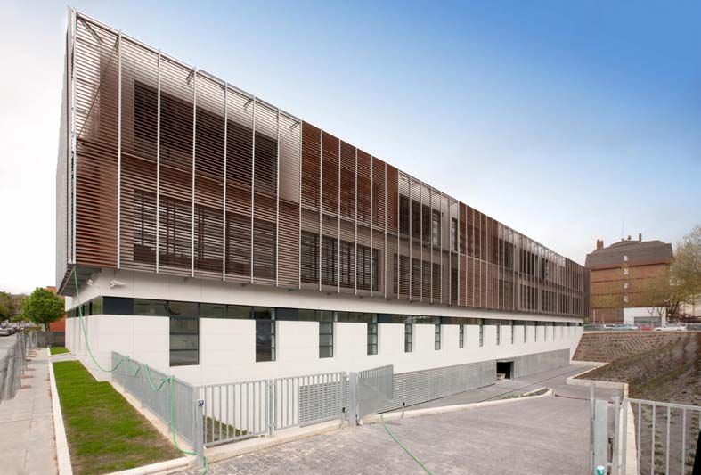
Second floor

The main requirement imposed by the UPV was that it should be a functional
building, without a defined occupant, and that it should allow for the performance
of different tasks during its life cycle; capital costs were limited, and would the
building fail to meet some of the financial constraints, it is on issues that should be
considered as ecological investments, which will pay off on due time.
On the outside, a second skin meets two objectives. On the one hand, and as the
activities to be performed inside the building may change in time, and therefore
some of the components of its façade may be altered, the envelope creates a
lasting, representative image of the building, and, on the other hand, these same
components can be used to implement some estrategies for the improvement of
energy efficiency.

                                                                          Cross-section

     GOP OFICINA DE PROYECTOS S.A.
             Architecture & UrbanPlanning
                                                                             Page 2 of 21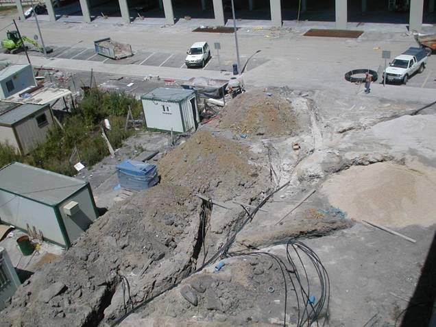
Every man-made space has got a perceived meaning, what it “says” when it is
entered. In this case, what has been intended is the space to convey an image of
work, of crativity and of research, with optimal environmental qualities and
comfort.
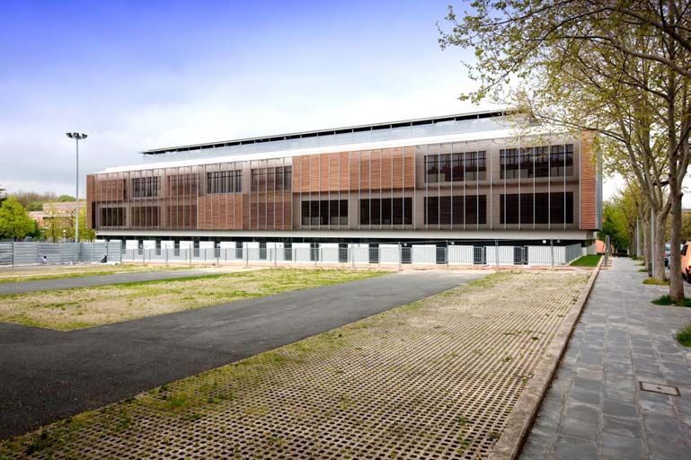
South Façade
Most of the decisions taken in designing this building were aimed at causing the
least impact on the environment, and, at the same time, at being healthy for its
occupants. This is a very important issue, because of the hazardous activities that
may take place in the building.
The most innovating measure implemented in the Research Centre is undoubtelly
the ground-to-water exchanger which uses the low enthalpy –temperature-
geothermal energy of the ground to reduce energy consumption. It must be noted
that this project does not only fulfill the New Building Code (CTE) Energy Savings
HE Basic Document, but that it over-acheives it on many requirements.
We have to keep in mind that the CTE is born with limited, imperfect objectives
because it focuses only on energy savings, without dealing with such issues as
comfort and human health, not to mention other ethically trascendent issues as
sustainability, although it is a step forward on the good direction
North Façade
GOP OFICINA DE PROYECTOS S.A.
Architecture & UrbanPlanning
Page 3 of 21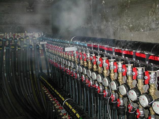
The Head team has supported these efforts, as it is concious of the growing
 awareness of man made impacts on the environment which constitutes a reality
 moving collective thought and ideals towards life activities and ways of thinking
 with a high-level commitment to preservation and progress, i.e. to sustainability.
 The project is also born with a calling to become a model for the rest of Public
 Administration buildings within de Basque Country.
 One of the main objectives of the Basque Agency for Energy (EVE) is to make the
 most of scientific and technological progress in the field of energy, and teaching
 and implementing new technologies; it is clear that their interests meet those of
 the University, in the areas of research, of training of specialists and of deepening
 on the knowledge of renewables.
 The project will be at the disposal of researchers and experts on the field of
 renewables, so its infrastructure and material ressources can contribute to
 teaching, to multidisciplinary research and to technological development and
 innovation. The building will be a reference model in the field of energy efficiency.
 The first thing to be evaluated was the envelope, because, according to the CTE,
 the roof and walls must be built so as to properly limit annual energy demand,
 based on local climatic conditions, on the use of the building and on winter and
 summer regimes.

1.2 BUILDING ENVELOPE
 The study of the envelope included, from the point of view of energy, the following
 issues:
 -     Thermal insulation of the non-glazed area of the façade, of the roof, of the
       floors and of other partitions of the envelope.
 -     The glazed surface.
 -     The shades that other components may throw on the envelope.
 The following table shows the values of K (U in the case of the CTE) value
 transmission coefficient (W/m2ºC) of the different partition components used in this
 project.

          Partition                          K partition.   KNBE CT 79   KCADEM   UCTE
          component
          Glazed openings                    1,80                        4,60
          Slab under LNC 1                   0,73           1,20         0,37     0,49
          Wall to LNC 1                      0,56           1,60         0,91     0,66
          Slab under LNC 2                   0,43           1,20         0,40     0,49
          Wall to LNC 2                      0,32           1,60         0,91     0,66
          Roof 1                             0,25           0,90         0,40     0,38

 Heat transmission coefficient Kg U (W/m2 ºC)
 Numbers in bold exceed values recommende by CADEM.
 The number in red exceeds the value being currently required.

      GOP OFICINA DE PROYECTOS S.A.
              Architecture & UrbanPlanning
                                                                                         Page 4 of 21
All the figures meet the requirements of the basic standard NBE CT in force at the
 moment of the project´s execution. Nevertheless, the building meets also the
 requirements of the CTE HE Basic Document “Energy Savings”.
 It is worth pointing to the fact that, as can be seen with the data shown, not
 meeting a specific value refered to the parameters required by the CADEM does
 not influence the building final appraisal.
 Coefficients of external walls (façades) do not appear on the previous table
 because their thermal behaviour must be studied jointly to the glazed openings,
 both in winter as in summer.
 The analysis performed establishes summer and winter heat flows, and compares
 them to the limit values of heat flow fixed on the basis of climatic zones, in order to
 decide if the behaviour of the external wall and of the glazed openings is energy
 efficient.
 In appointing heat flows, besides the coefficient U value of walls and openings,
 other parameters play a role, such as the wall thermal capacity, the windows solar
 factor and internal loads (set up lighting power, equipment power density, etc…).
 Once input data have been established, a simulation comparative study on
 heating and cooling demands is carried on, in order to optimize the energy
 efficiency of the building envelope.

1.3 STRATEGIES USED TO IMPROVE ENERGY EFFICIENCY
 Among the passive and active strategies employed for the design of the building,
 the following ones stand out:

 1.3.1 Shading
 Slats on the North façade are purely for decorative purposes, as this façade does
 not get any sun radiation; their only objective is therefore to give the building
 façade a formal integrity.
 For this reason, they are not included on the computer simulation.

            North Façade of the Research Centre at Álava Campus, without slats

      GOP OFICINA DE PROYECTOS S.A.
              Architecture & UrbanPlanning
                                                                                 Page 5 of 21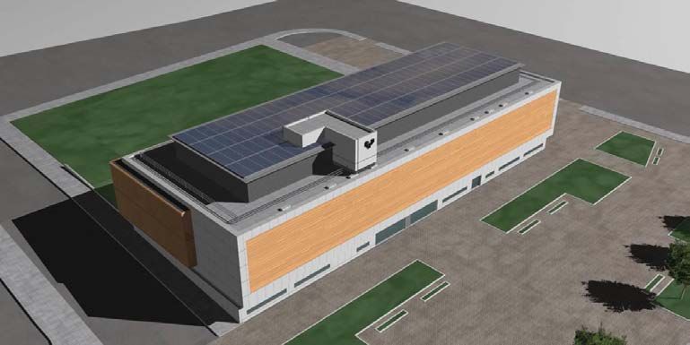
However, adjustable slats on the South side have been accounted for, because they
greatly influence sun radiation getting into the façade.

                                South façade of the simulation model.

                                      Façade protection with slats
       North: fixed slats.                                           South: adjustable slats.

    GOP OFICINA DE PROYECTOS S.A.
             Architecture & UrbanPlanning
                                                                                           Page 6 of 21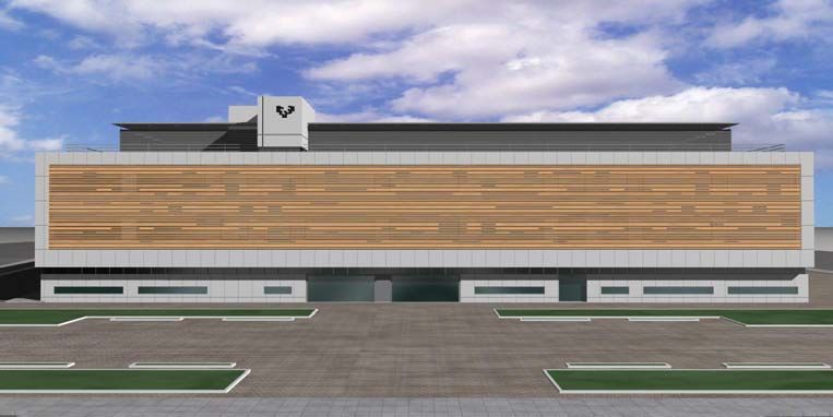
This illustration shows sun radiation received on a south façade window. On the
second illustration, we can see the effect of the slats. Calculations have been
conducted with south façade slats horizontally static. As they are ajdustable, sun
radiation can be more efficiently managed the year round.

  Simulation of direct sun radiation on the south façade, in June and January, respectively

1.3.2 PV panels. Double roof.
PV panels on the roof have two objectives. The typical one, is to produce power,
but they also act as a double roof for the shading of the building during the hottest
months of the year.
There will be 432 ISOFOTON PV panels to produce 65 kWp, with a peak power of
150 Wp.

     GOP OFICINA DE PROYECTOS S.A.
             Architecture & UrbanPlanning
                                                                                   Page 7 of 21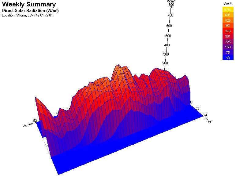
Electric power generated by PV panels the year round (LIDER data base).

            Electricity generated during the month of July (LIDER data base).

It is presumed that electric power produced by this system will be 52000 kWh/year
and, although it will be connected to the network, it is considered to be self-
consumed by the building, counting as energy savings on the global energy
calculations.

Even though the position of the panels is not the best one –their efficiency is
diminished by approx. 10%- and their layout compels to be very careful with their
cleaning to avoid dirt accumulation on them, it has been decided to set them
almost horizontally, to enhance their architectonic integration.

    GOP OFICINA DE PROYECTOS S.A.
            Architecture & UrbanPlanning
                                                                                Page 8 of 21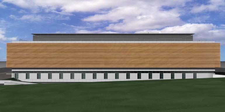
90

                                                             75
                                             100
                               W                        95

                                                                  50
                                            70          65
                                                                       E

                                       S

Geothermal exchanger
Reductions on energy demand for air conditioning systems are directly related to
the element with which heat is exchanged (air, water, ground). Air is most
commonly used, but it is not the most efficient, because of its temperature
oscillations throughout the year. Water is more stable regarding temperatures, so
exchanges are more efficient; nevertheless, there are other problems associated
to the exchange system (cooling towers), such as Legionellosis. Ground
exchanges are the most advantageous, because ground temperature is stable the
whole year, some 14ºC in this area, and the exhange can be made on a loop
system, without outside contacts.
Some factors have to be taken into account when designing a geothermal air
conditioning system, with a ground exchanger, which are not included on the
design for a conventional air conditioning system. First, the annual energy
demand of the building must be assessed, through model and energy simulation
computer programmes, in order to know the amount of energy that is going to be
given to or taken from the ground. This means that the designers of air
conditioning systems, who are used to work on terms of power, have to change
their minds and think on energy, sizing the plant not to adapt it to the energy
demand of the building, but to the peak power of the most unfavourable winter or
summer days. The following table shows the energy demand of the building, in
this case. As can be seen, annual energy demand is not in balance, because the
energy needed to heat the building is much higher than the energy needed to cool
it. This means a longer pipe for the exchanger; the length of the pipe needed is
optimized when the same amount of heat is taken of in winter as given in in
summer.

            Area                           Thermal power
            Without common
            areas                          Cooling (kWh)                   Heating (kWh)
                  (
            3.400                          253.000                         428.000

Another basic datum for the design of this kind of exchangers, which makes it
different from other air conditioning systems, it is the ground thermal conductivity
rate, obtained through an on-site, specific test. In this case, the test was
conducted by EVE, and the result was 4,1 W/m ºC, which is relatively high.
Finally, water-to-water heat pumps are chosen and their setting point fixed, based
on the temperature of water flowing in and out the building and the ground; this
way, we know the coefficients of performance (COPs) we have to deal with. These
COPs are 4-4,5 when heat is exchange with ground temperatures, whereas they
would be around 2 if the heat pump would exchange heat with the air.

    GOP OFICINA DE PROYECTOS S.A.
            Architecture & UrbanPlanning
                                                                                     Page 9 of 21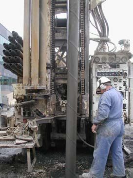
With all these parameters, the length of the heat exchanger and, therefore, drilling
needs, are calculated, making a financial-energetic analysis. That is to say,
because capital costs for the heat exchanger (drilling) are high, as it is a new
technology, it is important to design it taking into account the investment payback
period, from savings during its operation. For this project, two opportunities were
analyzed:
-      Meeting all thermal needs of the building with the exchanger.
-      Meeting 70% of heating demand and 100% of cooling demand.

The second option was chosen, which resulted on an exchanger consisting of
thirty, 135 m drilling holes, laid out on a 10x3 grid pattern, with a distance of 6.5m
between drillings. Predicted power set in the geothermal system is 300 kW for
heating and 250 kW for cooling; the rest of the energy demand for heating will be
met by an air-to-water heat pump, some 100 thermal kW. Geothermal power will
be adjusted with a series of pumps in order to get a better ground exchanger
performance due to simultaneity factors.
The following table shows the model for mean monthly temperatures of the fluid
on the ground; these temperatures are always much more moderate than outside
air mean temperatures, which means that the thermal lap that the heat pump must
overcome between the building and the thermal point is smaller, so the
compressor operates on better conditions, with a smaller demand and growing
energy savings.

           BASE LOAD: MEAN FLUID TEMPERATURES (at end of month)

        Month                Year 1         Year 2   Year 5   Year 10     Year 25
        JAN                   9.03           8.37     7.45     6.74         5.90
        FEB                   8.82           8.29     7.39     6.69         5.86
        MAR                   9.50           9.09     8.23     7.54         6.70
        APR                   9.52           9.11     8.28     7.59         6.76
        MAY                  10.20           9.72     8.90     8.22         7.40
        JUN                  12.96          12.39    11.55     10.88       10.06
        JUL                  15.57          15.00    14.14     13.48       12.67
        AUG                  17.14          16.66    15.81     15.16       14.36
        SEP                  15.80          15.40    14.59     13.95       13.16
        OCT                  12.23          11.88    11.13     10.49        9.71
        NOV                   9.64           9.27     8.57     7.94         7.16
        DEC                   8.83           8.43     7.76     7.13         6.35

From the model of the evolution of temperatures inside the exchanger, it must be
assessed that, during the operation life of the plant, the ground is not going to be
thermally saturated, i.e., that it won´t become too hot nor too cool.
Drilling is usually made with a torque-percussive equipment with a hammer, with a
diameter in the range of 150-200 mm, to the depth defined by calculations. A Ø 40
mm polyethylene double duct, PN 16 SDR 11, is inserted in the drilling hole,
forming a loop at the lower end. Then the drilling is filled with Ø 2-6 mm siliceous
sand, the last metres being sealed with bentonite.
In short, the geothermal system devised will be a source of heat and cold for the
building in winter and in summer, respectively, with annual energy savings of
368.000 kWh/year, approx., which will avoid the emission to the atmosphere of
132 tons of CO2/year.

     GOP OFICINA DE PROYECTOS S.A.
             Architecture & UrbanPlanning
                                                                           Page 10 of 21
The building will include a monitoring system to get information on the exchanger
performance; it will measure the volume circulating through the exchanger and the
incoming and outgoing temperatures from the heat pumps to the outside loop.
The idea is that the EVE will be in charge of the tracing of the exchanger
performance, so this experience can help improving future plants.
The EVE has already got some experience, since it has designed and built a
similar plant at the metallurgical research centre Azterlan, in Durango. This is
3.750 m2 building, in which the length of the geothermal exchange circuit is made
of 2.750 m drillings and 7.500 m of 40 mm polyethylene ducts, less than the length
forseen for the UPV building, which will count with 4.050 ml drillings. As the
Durango building is in operation since March, available data are still scarce, but
the measurements taken during the summer of 2006 show a mean electricity
consumption of 340 kWh/day for the set of heat pump/primary circulating pump,
which is really a low figure.
Azterlan metallurgic research centre, in Durango
.
GOP OFICINA DE PROYECTOS S.A.
Architecture & UrbanPlanning
Page 11 of 211.4 Domotics
As the integration of inmotics solutions in buildings is usually profitable to the
building owner, as well as to the final user and generally speaking to the whole
society, the Centre uses them in order to increase the efficiency of adopted active
and passive measures.
The first decision was to choose the EIB/KNX system, which is a worldwide
standard and the only one to meet the european EN50090 standard
recommended by the EU to be implemented in buildings. It is a warranty for the
present and for the future because of the options it presents and the facility to
adapt it to possible changes.
The system is adapted to the needs of every building; it allows for modifications
and extensions to be made in time, without the need to deploy new cabling, and it
can be adapted to future possibilities, such as Environmental Intelligence, i.e. the
capacity of the building to behave in accordance to the occupant´s use of
services.
The automation of a building like this is made in order to optimize energy
consumption and to obtain a suitable work setting, meeting the specified
requirements on management, comfort and security desirable on this kind of
premises. Energy savings and the optimal use of the building, with an economic
and rational operation, were the priorities when designing the building.
Thanks to this system, lighting and air conditioning energy consumption can be
efficiently and optimally managed, which contributes to the protection of the
environment and allows for the reduction of this consumption.
Its movement sensors secure that lights are not on when they are not necessary in
passageways. Constant adjustement of lighting in offices, laboratories and
conference rooms will prevent the consumption of more energy that it is necessary
for a sound visibility; when daylight is enough, lighting fixtures won´t light up. In
some cases, like in the garage, fluorescent lights won´t turn off, but their intensity
will be regulated to a minimum, avoiding switching on and turning off
consumptions, which are fluorescents main costs, until the presence of cars or
pedestrians is detected. With this solution, it is possible to get energy savings of
up to 70% on building lighting (mean savings being 40%, with a 3 years mean
return period).
On the other hand, the system provides an optimal air conditioning control. Heat
intakes in each room, area, floor… are individually adjusted through specific
controls. The system reduces heating demand automatically, when the rooms or
the building are empty, even for a short time. The thermal efficiency of the walls
and roof will be measured in the same way. It is forecast that these measures will
allow obtaining energy savings on air conditioning of more than 30% per year.
Besides, the whole system can be managed from a checkpoint (even from a PDA),
which will make daily management tasks easier for the building staff.
Resources optimization and comfort, security and savings solutions are the
responsability of the final user and of UPV maintenance service. The user enjoys
light and temperature conditions automatically, rationally and without a need for
GOP OFICINA DE PROYECTOS S.A.
Architecture & UrbanPlanning
Page 12 of 21manual controls. Forecast total savings will allow for a 3-5 years return period of
the system.
1.4 ENERGY EFFICIENCY STUDY
The aim of this kind of study is to show that the building meets all the
requirements demanded by Building Regulations, and specifically by the HE Basic
Document “Energy savings”, and also to allow for the optimization of the
exploitation of natural resources.
The study analyzes different possibilities to improve the building performance at
the design stage, with affordable and profitable measures, from the technical as
well as the financial point of view. These improvements can be taken into account
in the project if the study is made early at the design stage; in this way,
suggestions can be analyzed and evaluated, incorporating into the final design
those which are really the most suitable from the point of view of energy.
The figures which are analyzed are:
- Heating demand
- Electric demand for lighting
- CO2 emissions associated to both consumptions.
For the calculation of air conditioning demand, the CIBSE dynamic evaluation
method has been used; it was developed by the british Chartered Institute of
Building Service Engineers, and it enables the assessment of heating and cooling
services properly, i.e. the net energy demand foreseen and maximum power value
necessary on consumption peaks.
In the case of lighting demand, the starting point was daylighting in Vitoria sky,
which brings on 7518 luxes (Tregenza formula) at an open space on a cloudy day.
This value represents lighting minimal value for 85% of the time between 9:00 and
17:00 during the whole year
Direct sun radiation
GOP OFICINA DE PROYECTOS S.A.
Architecture & UrbanPlanning
Page 13 of 21Electric energy demands for lighting have been also evaluated, but without going
into details on its surface distribution and other related issues, such as heat, the
integration of daylight, etc… Notwithstanding, looking ahead of the CTE
requirements, the building makes use of a circuit at the perimeter of the building,
the closest to the façade, with mixed lighting which adjusts artificial lighting
depending on existing daylight.
The methodology used for the analysis of improvement opportunities was to study
the following cases:
Case 0 CTE reference building
Obtained data are shown on the following table.
HEATING COOLING
LOAD LOAD
(kWh) (kWk)
435.000 243.000
Per m2 128 71
These figures are similar to those obtained from preliminary energy demand
calculations for the sizing of the exchanger.
Case 1 Basic project building
HEATING COOLING
LOAD LOAD
(kWh) (kWk)
412.000 170.000
2
Per m 121 50
Which represents a 5,5% improvement on heating, in relation to the reference
building and a 30% improvement on cooling as a consequence of the effect of
the shading on the south façade.
From this moment, the most interesant part of the job is carried out, and it consists
on studying the effect of the possible improvement settings.
The study carried out analyzed the following possibilities:
Case 2 Substituting the kind of glass on the basic project building with a simple
double glazing with Planitherm 4-12-4 type layer treatment with a light
transmission of 76%, a solar factor of 0,63 and a thermal transmission coefficient
U=1,74W/m2K.
PROJECT BUILDING CASE 2 GLAZED BUILDING
HEATING LOAD COOLING LOAD HEATING LOAD COOLING LOAD
(kWh) (kWk) (kWh) (kWk)
412.000 170.000 371.000 180.000
Por m2 121 50 109 52
In this case, the obtained improvement on heating means an 11% improvement,
with a 7% worsening on cooling, this worse datum being compensated by the
improvement on air conditioning.
The use of glass with a lesser solar factor implies that cooling demands are
smaller, because incident radiation is reduced. As cooling consumption is a small
GOP OFICINA DE PROYECTOS S.A.
Architecture & UrbanPlanning
Page 14 of 21part of energy consumption, it seems more interesting to focus on the
improvement of heating consumption.
Case 3 Substituting glass with a double strength glass with simple air space
Cool-lite 6-12-4 type, with light transmission of 50%, a solar factor of 0,36 and a
thermal transmission coefficient U=1,74 W/m2k.
PROJECT BUILDING CASE 2 GLAZED BUILDING
HEATING LOAD COOLING LOAD HEATING LOAD COOLING LOAD
(kWh) (kWk) (kWh) (kWk)
412.000 170.000 373.600 172.000
Por m2 121 50 110 51
In this case, heating improvement is 10% and cooling losses 1%.
Case 4 Increasing polyurethane thickness on polyurethane insulation by 15 mm,
so total thickness is 50mm.
PROJECT BUILDING CASE 2 GLAZED BUILDING
HEATING LOAD COOLING LOAD HEATING LOAD COOLING LOAD
(kWh) (kWk) (kWh) (kWk)
412.000 170.000 405.000 172.000
Per m2 121 50 119 51
Increasing polyurethane insulation thickness is not a sound strategy, because it
does not improve almost anything and the situation gets worse during the
summer, as it does not allow the building to dissipate the heat produced by
internal loads.
From the analysis of the studied cases, it can be concluded that the solution of
improving glazing is better than the improvement of the façades.
Results obtained for electric energy demands for lighting
GOP OFICINA DE PROYECTOS S.A.
Architecture & UrbanPlanning
Page 15 of 21Mean Lighting Mean Equivalent Artificial Potency Total Day Total
luminance area natural potency input (lux) per Unit Potency Night
per m2 (m2) input (lux) (W/m )2
(W/m2) (W) Potency
(W)
Basement 150 1.742 25 0,81 125 4,06 7.077 8.492
Classrooms and
600 1.783 100 3,25 500 16,25 28.974 34.769
Offices
Laboratories 900 2.485 100 3,25 800 26,00 64.610 72.686
Corridors 300 1.458 100 3,25 200 6,50 9.477 14.216
Restrooms 1
300 450 100 3,25 200 6,50 2.925 4.388
and 2
TOTAL 7.918 105.986 126.058
Energy at
Basement 27.897 kWh/year
Offices and classrooms 114.215 kWh/year
Laboratories 247.618 kWh/year
Corridors 41.509 kWh/year
Restrooms 1 and 2 12.812 kWh/year
TOTAL 444.050 kWh/year
It is worth noting that energy consumption for lighting represents one fourth of the
total energy consumption of the building.
Heating Cooling TOTAL
Tn/year Tn/year Tn/year
CTE reference
87 36 123
building
Project building 82 25 107
Case 1 4-12-4
Climat. with 73 26 99
Planitherm
Case 2 6-12-4
74 25 99
Cool-Lite
Case 4
81 25 106
50 mm insulation
Lighting - - 56
ENERGY EFFICIENCY CERTIFICATION (CADEM)
As seen on the construction project, the building shows very efficient systems for
every power plant studied.
- For the construction system, all partitions, both façades as partitions to
unheated rooms, have thermal insulation, and low-emissivity glass is used.
Mechanically adjustable slats are used to avoid excessive sun radiation
through windows in summer.
GOP OFICINA DE PROYECTOS S.A.
Architecture & UrbanPlanning
Page 16 of 21- For air conditioning, the system is based on high performance heat pumps
with geothermal profit, primary air conditioners with heat recoverer units and
a central, computer-assisted control system.
- For lighting, the system is based on low power consumption lamps and
fluorescent lamps, with power regulation according to daylighting levels
around the whole building.
CADEM Energy Efficiency Certificate compares energy consumption of the
project building to the consumption of this same building if only applicable norms
were met, both for the construction system as for thermal and electric systems.
After the computer simulation carried on both on the reference building as on the
building to be constructed, foreseen consumptions are as follow:
System Reference building Project building
Heating 243.000 149.000
Lighting 115.000 87.000
Cooling 144.000 89.000
Other 49.000 49.000
PV - -
TOTAL 551.000 322.000
Note: energy consumption kWh/year
The share of consumptions can be drawn as follows:
Reduction on energy consumption represents a reduction on polluting particle
emissions to the atmosphere, as shown on the following table:
GOP OFICINA DE PROYECTOS S.A.
Architecture & UrbanPlanning
Page 17 of 21Energy Reduction NOx CO SO2 P.S. V.O.C CO2
Electricity 229.000 173 34 1.134 34 14 115.000
Note: Polluting emissions reduction (Kg/year)
P.S: Solid particles
V.O.C: volatile organic compounds
The classification depends on the consumption coefficient, which is the project
consumption divided by the reference consumption, in this case:
- Cosnsumption coefficient= 322.000/551.000= 58,5 %
With this value, the building obtained energy certification is as follows:
The objective when evaluating non residential buildings is to acheive that new
buildings are able to provide high levels of comfort to its occupants, in order to
improve their productivity and their well-being, minimizing at the same time their
energy consumption.
CADEM board at construction site.
GOP OFICINA DE PROYECTOS S.A.
Architecture & UrbanPlanning
Page 18 of 211.5 CONCLUSION
Requirements fixed by regulations are the lowest that a building must legally meet,
but they can be perfectly exceeded by means of bioclimatic strategies, which do
not have to be a burden on the final product cost and which, in any case, should
be viewed of as an investment.
Designing and implementing a geothermal air conditioning system is going a step
further on the use of renewable energy resources, because its application was
until now limited at an experimental level. Again, the setting of PV panels implies
the provision of a clean system for the production of energy and for securing an
alternative supply of energy to the Centre and its laboratories critical experiment
equipment and for the preservation of specimens, very sensitive to conventional
network blackouts. Finally, domotics related initiatives mean a continuous,
secured optimization of energy efficiency, based on the proper adjustments made
every time they are needed, on the performance of the different building plants
and components; this has got a decisive effect on energy consumption and
savings.
With this building, the Public Administration, and specially the Basque Country
University has bet again for Energy Efficiency, which, being only a means towards
sustainability, is nonetheless a step forward to achieving a sustainable
development, i.e., development which satisfies present needs without
compromising the capacity of future generations to satisfy their own needs, as it
was defined by the Brundtland Committee in 1987.
GOP OFICINA DE PROYECTOS S.A.
Architecture & UrbanPlanning
Page 19 of 211.6 BIBLIOGRAPHY / REFERENCES
Bose, J.E. et Al. 2001. “Advances in Ground Source Heat Pump Systems an
Internacional Overview”
Caneta Research Inc 1995. “Comercial/Institutional Grond-Source Heat Pump
Engineering Manual”. ASHRAE
Caneta Research Inc 1998. “Operating Experiences With Commercial Ground-
Sources Heat Pump Systems. ASHRAE
EPA 1993. “Space Conditioning: The Next Frontier, Office of Air and Radiation. R-
93-004
FTA 1993. “Ground-Source Heat Pumps Applied to Federal Facilities-Second
Edition”
GHPC 1999. “Geoexchange Heating and Cooling Systems: Fascinating Facts”
IGSHPA, Varios manuales (6) sobre diseño e instalaciones
Kavanaugh, S. P. & Rafferty, K. 1997. “Ground-Source Heat Pumps Design of
Geothermal Systems For Commercial and Institutional Buildings”. ASHRAE
McCray, K. (Ed) 1999. “Guidelines for the Construction of Vertical Boreholes for
Closed Loop Heat Pump Systems. National Ground Water Association-
Geoexchange
Monasterio R., Hernández P., Saiz J. 1993 “La bomba de calor. Fundamentos,
técnicas y aplicaciones” Serie electrotecnologías MacGraw Hill/ Eve/ Iberdrola
Shonder, J.A. & Beck, J.V. 2000. “A New Method to Determine the Termal
Properties of Soil Formations from In Situ Field Tests. Oak Ridge National
Laboratory. USDOE
VDI 2004, VDI 4640 Termal Use of the Underground, Part 2 Ground Source Heat
Pump Systems.
1.7 CREDITS
UPV. Servicio de Patrimonio y Obras
Support for the procurement and the execution of the bioclimatic project, and for
subsidies transactions.
Ignacio Ruiz de Gordejuela
EVE (Ente Vasco de Energía)
Technical consultancy for the exchanger design.
In situ tests performing.
Iñigo Arrizabalaga
CADEM
Energy Efficiency Certification of Buildings
Oscar Puche Ormaetxea
CIDEMCO Technical centre
Energy efficiency calculations
Sergio Saiz
GOP OFICINA DE PROYECTOS S.A.
Architecture & UrbanPlanning
Page 20 of 21ENERGESIS INGENIERIA S.L.
Collaboration to the exchanger preliminary design
Teresa Magraner
ASETECNIC S.L.
Services project
José Luís García Cruz
ETAP
Lighting
Alfonso González Barandalla
TECDOA S.L.
Domotics
JordiMonreal
GOP OFICINA DE PROYECTOS S.A.
Architecture & UrbanPlanning
Page 21 of 21You can also read


