BRI - UTas - AAD Neutron Monitor Latitude Survey
←
→
Page content transcription
If your browser does not render page correctly, please read the page content below
..                   Bartol Research Institute, University of Delaware
         ..                  217 Sharp Laboratory, Newark, DE 19716
          ..                 Phone: (302) 831-8111
           ..                Fax: (302) 831-1843
            ..               Email: penguin@bartol.udel.edu

        Bartol Research Institute

        BRI - UTas - AAD
        Neutron Monitor
        Latitude Survey
.   .            .   .   .        .           .           .            .         .

        Equipment Description and Operating
        Procedures for the 2004-2005 Voyage of
        the USCGC Polar Star (WAGB-10)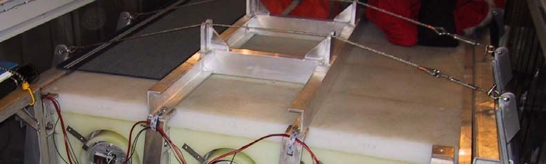
..
 ..
  ..
   ..
    ..

Bartol Research Institute -
University of Tasmania -
Australian Antarctic Division
Neutron Monitor Latitude Survey

Equipment Description and Operating
Procedures for the 2004-2005 Voyage of the
USCGC Polar Star (WAGB-10)

Investigation Overview
Cosmic rays are energetic particles (including electrons, protons, and heavier elements) pro-
duced in the galaxy by processes that are not fully understood. The propagation of these par-
ticles is influenced by magnetic fields in the solar wind and in the magnetosphere of the
Earth. By recording variations and fluctuations in the cosmic ray intensity, we are able to
investigate changes in these magnetic fields.

Neutron monitors measure the “debris” left after the primary cosmic rays enter the atmos-
phere of the earth. Much of the information regarding the composition of the cosmic rays is
lost in this process, but the large size of the neutron monitor permits an extremely accurate
determination of the intensity of cosmic rays striking the atmosphere directly above the detec-
tor. The paths taken by these cosmic rays are influenced by the magnetic field of the earth, so
that the monitor is “looking” toward a particular direction in space. This direction is in gen-
eral very much removed from the local vertical. Our network of neutron monitors measures
the anisotropy of cosmic rays.

Near the equator, the magnetic field of the earth is more effective in keeping cosmic rays
from reaching the atmosphere than it is near the poles; so only higher energy particles are
admitted. A parameter called the “Effective Cutoff Rigidity” can be calculated to summarize
this process. (Rigidity, or momentum per unit charge, is closely related to the particle energy
but is more useful in the actual calculations.)

In a latitude survey, a neutron monitor is transported through a range of cutoff rigidities as
rapidly as possible. (Speed is important because the cosmic ray intensity changes with time.)
The variation in counting rate of the neutron monitor as a function of effective cutoff rigidity
permits a measurement of the cosmic ray spectrum (integrated over particle type) at energies
where direct spacecraft measurement is difficult or impossible due to the large detector sizes
required. Observed deviations from perfect ordering of the data by the calculated cutoff ri-
gidity may be used to produce refined models of the magnetic field of the earth.

Further information about cosmic rays and the neutron monitor program of which this inves-
tigation is a part, may be found on our web site: www.bartol.udel.edu/~neutronm/

                                        2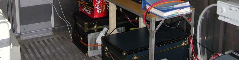
Project Collaboration
The University of Delaware Bartol Research Institute, the University of Tasmania, and the
Australian Antarctic Division are collaborating on annual latitude surveys through and be-
yond the solar minimum expected in 2007-2008. Primarily, the Australian contribution is
equipment, while the Bartol (with NSF and USCG support) contribution is operation and lo-
gistics. Both groups participate in scientific evaluation of the data. Key personnel are:

John Bieber, Professor, University of Delaware, is principal investigator of NSF project S-
120. His primary research interest is calculation of particle propagation in magnetic fields.
(john@bartol.udel.edu)

Paul Evenson, Professor, University of Delaware, is a co-investigator on project S-120. He is
the primary science contact for the annual latitude survey. His primary research interest is
measurement of cosmic ray energy spectra using high altitude balloons and spacecraft.
(penguin@bartol.udel.edu)

Leonard Shulman, Electronics Engineer, University of Delaware Bartol Research Institute, is
responsible for technical development and maintenance of the Bartol network of neutron
monitors (Thule, Inuvik, McMurdo, Goose Bay, Ft. Smith, Peawanuck, Nain, South Pole,
Newark, and the installation on the Polar Star or Polar Sea). (shulman@bartol.udel.edu)

John Humble is with the University of Tasmania School of Mathematics and Physics.
John.Humble@utas.edu.au

Marc Duldig is Program Leader for Space and Atmospheric Sciences, Australian Antarctic
Division. marc.duldig@aad.gov.au

Equipment Overview
The TasVan. All equipment is housed in a standard, insulated shipping container often re-
ferred to as the “TasVan”, which conforms to all applicable standards and may be handled in
any standard way. When moving with a fork lift, note that the load is unbalanced. For opera-
tion, the TasVan requires both 110 and 220 volt electric power and a supply of seawater for
internal cooling.

                                       3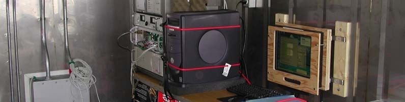
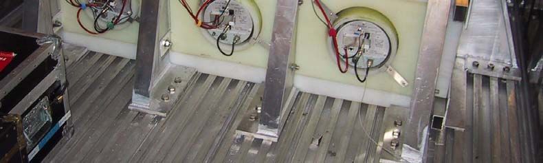
3NM64. The scientific instrument is a neutron monitor, technically known as 3NM64. The
NM64 is the basic design; the “3” refers to the fact that there are three units installed in the
TasVan. The NM64 is constructed mainly from lead and polyethylene, with the neutron de-
tectors inserted from the side. The detectors are cylinders filled with boron trifluoride gas (en-
riched in the isotope boron-10). The boron nuclei react with neutrons and undergo nuclear
fission. The resulting bursts of energy ionize the gas and eventually produce electrical pulses
on a wire maintained at a potential of (typically) -2800 volts. These electrical pulses are
counted by the electronics inside the TasVan.

Electronics. Racks inside the TasVan record all data automatically, along with ship’s posi-
tion (derived from GPS receivers) and barometric pressure. Accurate position and pressure
information is vital to the success of the experiment. The ship’s log serves as a backup data
source in case of failure of the automatic units.

Climate Control. Automatic heating and cooling systems are installed in the TasVan to
maintain proper operating conditions for the equipment. Different systems are used during
different parts of the voyage. The transfer of systems is typically made during port calls in
Australia or New Zealand, both when entering and leaving Antarctic waters.

Equipment Description
In this section, we give a brief but specific description of the construction and operation of
individual pieces of equipment. Further information may be found in the blue ring binder fur-
nished to the Science Officer. Questions should be sent to penguin@bartol.udel.edu and /or
shulman@bartol.udel.edu. (If urgent, send to both
as we are often out of town.)

Electric Service. Both 220 volt and 110-volt
power enter the TasVan. The 220-volt service
powers two resistance heaters and a heat pump
that uses seawater as a heat source or sink. The
110-volt service powers the electronic equipment.
Circuit breakers for both are found inside the
TasVan on the forward bulkhead.

                                         4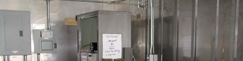
Resistance Heaters. Located on both sides of the TasVan. Power is controlled by the cir-
cuit breaker for the 220-volt service. Turning this breaker “off” disconnects power to the unit.
The resistance heaters are used only in Antarctic waters. They are secured during the passage
from Seattle to Sydney and on the return passage from Adelaide to Seattle. Thermostatic con-
trols for these heaters are located on the heaters.

Seawater Heat Pump. Located near the forward bulkhead on
the port side. Power is supplied by a breaker for the 220-volt
service. This unit provides both heating and cooling for the
TasVan. The control is located on the port wall, near the unit.
When operating, this unit must be supplied with flowing water,
and left in automatic mode with a set point of 70 degrees. The
heat pump cannot be used in Antarctic waters because the wa-
ter temperature is to low for proper extraction of heat. It is se-
cured southbound at Sydney and reactivated northbound at
Adelaide. When secured, the seawater supply must be discon-
nected and the circuit breaker turned off.

Electronics Rack. Most of the electronics are located in the rack adjacent to the onboard
computer. The documentation “Blue Book” should be kept available for reference.

Uninterruptible Power Supply (UPS). Located in the electronics rack. Power is controlled
by a breaker in the 110 volt service. The on-off switch is located on the rear of the unit. The
UPS conditions all of the power to the electronics. It provides approximately 30 minutes op-
eration of the electronics in case of brief interruption in ship’s power. If a longer interruption
is expected, the unit should be secured by turning the switch on the back “off”. To restart,
turn the switch on the back “on” and push the “on” indicator on the front panel. Normal oper-
ating mode is the green “online” indicator on.

                                         5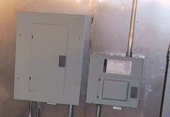
University of Tasmania Data Logger. Located in the electronics rack, the data logger re-
cords data from the detectors and one barometer in a solid-state memory. The Logger has its
own DC power supply. Data summaries from the Logger appear on the computer display for
diagnostic purposes. The one-second light should flash once per second in normal operation,
with occasional longer flashes. If this light is not flashing, or if there is no recent transmission
displayed on the screen of the computer, the “Reset” button should be pushed. If no lights
flash when the reset button is pushed, check that power is reaching the unit from the power
supply. No other field service is possible.

Footlockers and Storage Cases. Footlockers and storage cases, secured with bungee
cords, contain spare parts and documentation intended for use by the investigators during ser-
vicing visits to the ship. Entry by ship’s crew is authorized only by specific invitation or in
connection with official ship’s business.

BP-28 Neutron Detectors. BP-28 (Chalk River) neutron detectors are mounted in the NM-
64. They are self contained and should not be serviced by ship’s personnel. Input is low volt-
age power to the electronics, with an internal supply generating -2800 volts (nominal) to the
detector. Outputs are logic pulses, each of which corresponds to the detection of a single neu-
tron. The units operate independently, so it is possible to disconnect an individual unit if a
failure causes interference. Since the units are daisy-chained, such removal may require re-
configuration of the wiring. The logic pulses are counted by independent and redundant data
acquisition systems (the Logger and the Bartol Electronics).

Low Voltage Power Supply. Located in the electronics rack. Powered from the 110 volt
UPS. Provides low voltage power to the Bartol Electronics (and through this to the Remote
Units). Normal state is “power on”. Fluctuations in current at a one second rate are normal
and are due to the operation of the readout electronics. Cycling “power off” / “power on” re-
sets the electronics.

Bartol Electronics. Card cage located in the electronics rack. Several printed circuit boards
perform different functions, to produce a consolidated data stream for analysis by the com-
puter. They are powered from the Low Voltage Supply. To reset, cycle the power.

Master Unit. One of the boards in the Bartol Electronics, the Master provides power to the
remote units and collects data from these units. Normally the Master has nothing visible ex-

                                          6
cept the flashing LEDs (green heartbeat 2 or 3 times per second, and red busy once per sec-
ond). However, if any Remotes do not respond, the Master will display the number of units
that had an error during the last readout. To reset, cycle the power.
Remote Units. Located on the neutron detectors, and powered from the Master, the Remote
Units operate the detectors and count pulses from them. To reset, cycle the power to the Bar-
tol Electronics.
Digiquartz Barometer(s). Mounted on boards in the Bartol Electronics. One or two units
may be installed. The output consists of two square-wave signals, with frequencies related to
the barometric pressure and operating temperature by a complex formula. The outputs are
sent redundantly to the Logger and the Bartol Electronics.
AIR Barometer. Located in the electronics rack. Output is a digitally coded signal giving
barometric pressure. Powered and read by the Bartol Electronics.
Analog Tiltmeters. Redundant sensors are located on a board in the Bartol Electronics. Out-
put of each sensor is three analog signals giving inclination on two axes and unit temperature.
The values shown on the display are uncalibrated engineering units.
PotchMon. Mounted near the access door, the Potchefstroom University (South Africa) cali-
bration monitor is a miniature version of the neutron monitor installed in the Tasvan. It is be-
ing carried to test and calibrate it against the standard monitor. This unit operates automati-
cally, with backup data transferred to the computer via an Ethernet link. If there is an error
message displayed on the LCD, the unit must be reset. To reset, power it down according to
the instructions on the LCD, then remove the white cap on the power button and press the
button.
Lights. Lights in the TasVan should be kept off when not needed. Heat from the bulbs can
influence thermal control.
7Computer. Located near the electronics rack. Powered from the 110 volt UPS. This is a
standard PC, operating under Windows XP which accumulates and records data using pro-
grams written in Visual Basic Version 6.0. The hard drive contains the operating system and
is used to record the daily log files for transmission to the experimenters via e-mail along
with the full time resolution dataset. An identical, spare PC is normally kept in one of the
crates in the Tasvan. If it is necessary to reboot the computer, power to the electronics rack
MUST be switched off prior to and during the reboot. If instrument data are presented to the
computer during reboot, it often detects this as a “pointing device” and causes the mouse
pointer to jump around on the screen. If this happens, power off the electronics to stop the
mouse pointer from jumping, and shut down the computer normally. Then reboot with power
to the electronics still off.
CD Burner. Installed in the PC. Used for backup of data and software during visits by the
investigators.
“Floppy” Drive (3.5 inch). Installed in the PC. Used during the voyage to copy daily log
files for transmission to the investigators via e-mail. A special program is provided to auto-
mate this operation. Details are given in the section on the daily station check
Rocket Port. Installed in the PC, the Rocket Port adds serial ports COM3 through COM6.
COM3 is used for general communication with the Bartol Electronics. COM4 is used to com-
municate with the Logger. The latest message from the Logger is always displayed on the PC
screen. COM5 is currently unused. COM6 is used as required for a calibration barometer.
There is a parameter file on the computer that allows straightforward reconfiguration of these
ports.
GPS Receivers. Two units are
mounted in the rack to furnish data to the
consolidated data stream. The most re-
cent record read from each is always
displayed on the PC screen. The last
valid position from each is displayed in a
separate location on the PC screen.
There is also a GPS receiver in the cali-
bration monitor. Antennae for all three
receivers are mounted on the forward
bulkhead of the Tasvan, as shown in the
photograph. The antennae are all identi-
cal, and may be interchanged if neces-
sary for troubleshooting.
Operation Overview
Operation of the neutron monitor in the TasVan is fully automatic. All data are recorded ei-
ther on hard disks or in solid-state memory. Periodic visits by the investigators are made to
download the data and to maintain and upgrade the hardware and software.
Activities requested of the ship’s crew are designed to diagnose and correct minor problems
that might develop in the instrumentation and to alert the investigators to major problems that
might require special repair visits to the ship. The most important part of the process is the
daily transmission of a diagnostic log file to the investigators via e-mail. Daily entry (weather
permitting) into the TasVan is requested to obtain this log file and to perform a series of in-
spections. The investigators will examine the transmitted log files, and may request further
diagnostic and/or repair activity from the crew.
8A checklist and log form is provided, covering one week of daily checks. These forms should
be retained on the ship for reference by the investigators during the servicing visits. If anoma-
lies are noted, the relevant forms may be sent via Fax (302) 831-1843, attention of Len Shul-
man, or the observations may be summarized in an e-mail message sent to shul-
man@bartol.udel.edu with a copy sent to penguin@bartol.udel.edu.
An immediate response to anomaly reports should be expected. The crew may take reason-
able corrective action before receiving a reply from the investigators, but all such actions and
the results of them should be reported to the investigators via e-mail or Fax.
Daily Station Check
The following operations and checks should be performed on a daily basis. Each item should
be checked off on the checklist, or a reading entered, as appropriate. The light in the TasVan
should be kept off when not in use, and the door kept closed as much as possible to ease the
strain on the climate control system.
In transmitting the log files, please do not transmit the file for the current day unless explic-
itly requested. The file is updated from time to time during the day, and is only complete
when the day ends. Copying the file during an update may cause a system crash. Note that
the computer is always kept on Universal time. The current day can always be found from the
updating time on the computer screen. The date is part of the file name.
Monitor Summary. Observe the operation of the system as summarized by the screen dis-
play on the PC. All remote units should be responding. If the display is frozen, first try to
close the program with the (X) box. If that does not work, use CTRL-ALT-DEL and try to get
Windows to terminate the program. If either of these works, restart the program by double
clicking on the “Earth” icon. If all else fails, reboot Windows. Be certain that the “DA
Power” is OFF before rebooting Windows. The program should load automatically. When it
has loaded, the “DA Power” should be turned back on.
PotchMon. Observe the operation of the Potchefstroom Calibration Monitor as indicated on
the LCD screen attached to the unit. Reset if necessary. To reset, shut down the monitor fol-
lowing instructions on the LCD display. Then remove the white cap on the power switch, and
press the power button.
GPS. Messages from both units should appear once per second, and most should contain
valid positions. The separate display of the “last valid” position should be recent and reason-
able. Interchange the antennae as a diagnostic if one unit is not responding. There is a spare
antenna in the footlocker.
Barometers. Entries for all barometers on the screen display should be consistent and up-
date at least once per minute.
Tiltmeters: Display on the computer screen should update once per second, and should agree
with the observed motion of the ship.
Logger. The message on the Monitor screen should be no more than one hour old, and the
one-second light on the logger itself should be flashing. No other lights should be on. Push
the Logger reset if this is not the case.
Temperature. Record the temperature from the display near the electronics rack.
Humidity. Record the humidity from the display near the electronics rack.
9UPS. Check that the green “online” light is on.
Bartol Electronics. Check that the lights are flashing in their normal patterns
Thermal Control. When the heat pump is being used, check that the control is set to auto
mode. The temperature set point should be 70 degrees. Check the seawater connections for
leaks, and check that the condensate drain is open. If the heat pump is secured, verify proper
operation of the resistance heaters. The heat pump and the resistance heaters should not be
used at the same time.
Log File. Place a DOS formatted floppy disk in the drive, and bring the log copy window to
the front by clicking on the taskbar. Click the “Copy File” button, and select the file to be
copied with the dialog box. (This will usually be near the end of the list; I have not found a
way to get Windows to make the end of the list the default location) Clicking the “OK” but-
ton will copy the selected file to the disk. E-mail the file to penguin@bartol.udel.edu as
soon as possible. The file contains only printing ASCII, so it may be edited into a message or
sent as an attachment. To restart the Log Copy program, double click the floppy disk icon on
the screen. The program also restarts when Windows is re-booted.
10You can also read