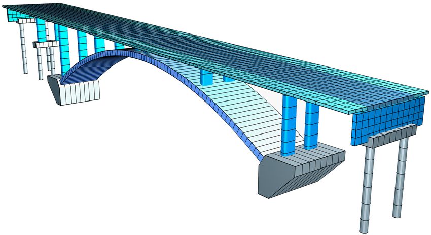
BRIDGE CHECKS ACCORDING TO EN 1992-2 WITH NATIONAL ANNEXES AUSTRIA AND GERMANY - INFOGRAPH GMBH
←
→
Page content transcription
If your browser does not render page correctly, please read the page content below
Bridge Checks

according to EN 1992-2
 with National Annexes
  Austria and Germany
The description of program functions within this documentation should not be considered a warranty of product features.
All warranty and liability claims arising from the use of this documentation are excluded.

InfoGraph® is a registered trademark of InfoGraph GmbH, Aachen, Germany. The manufacturer and product names
mentioned below are trademarks of their respective owners.

This documentation is copyright protected. Reproduction, duplication, translation or electronic storage of this document or
parts thereof is subject to the written permission of InfoGraph GmbH.

InfoGraph® Software uses Microsoft® MFC and Intel® MKL Libraries.

© 2019 InfoGraph GmbH, Aachen, Germany. All rights reserved.

Title image: Federal motorway A 44, bridge construction near Hessisch Lichtenau.
Courtesy of MEHLHORN und VIER Ingenieurgesellschaft mbH, Kassel, Germany.
Contents

Contents
Basics                                                                                     3

Input                                                                                      3
          Type of Structure                                                                3
          Load Model 1 for Road Bridges                                                    4
          Actions and Action Combinations                                                  6
          Definition of an Action                                                          7
          Definition of an Action Combination                                              9
          Partial Safety Factors                                                          10
          Section Inputs                                                                  10
          Analysis Settings                                                               21
          Single Design                                                                   22

Prestressed Structures                                                                    23
        Internal Prestressing                                                             23
        External Prestressing, Mixed Construction                                         28
        Variation of Prestressing                                                         28
        Creep and Shrinkage                                                               29
        Relaxation of Prestressing Steel                                                  30

Checks in the Ultimate Limit States                                                       31
      Design Combinations                                                                 31
      Stress-Strain Curves                                                                31
      Design Internal Forces                                                              32
      Design for Bending With or Without Normal Force or Normal Force Only                34
      Minimum Reinforcement against Failure Without Warning                               35
      Surface Reinforcement                                                               35
      Design for Lateral Force                                                            36
      Design for Torsion and Combined Stressing                                           39
      Check of principal compressive stress for combined actions                          40
      Punching Shear                                                                      41

Checks against Fatigue                                                                    41
      Design Combinations                                                                 41
      Stress-Strain Curves                                                                41
      Fatigue of longitudinal reinforcement, shear reinforcement and prestressing steel   42
      Fatigue of concrete under longitudinal compressive stress                           43
      Fatigue of the concret compressive struts under lateral force and torsion           44
      Special characteristic of shell structures                                          45

Checks in the Serviceability Limit States                                                 46
      Design Combinations                                                                 46
      Stress-Strain Curves                                                                46
      Stress Analysis                                                                     47
      Limiting the Concrete Compressive Stresses                                          48
      Limiting the Reinforcing and Prestressing Steel Stresses                            48
      Decompression Check                                                                 49
      Concrete Tensile Stresses in Bridge Transverse Direction                            49
      Minimum Reinforcement for Crack Width Limitation                                    50
      Crack Width Calculation                                                             52
      Crack Width Check by Limitation of the Bar Distances                                53
      Determining the Effective Area Ac,eff                                               54
      Limiting Diagonal Principal Tensile Stresses                                        56
      Limiting Deformations                                                               57

Results                                                                                   58

Examples                                                                                  60

© InfoGraph GmbH, February 2019                                                                      1
Contents
Road Bridge in Solid Construction 60
Railroad Overpass with Prestressed Concrete Superstructure 69
Bridge Abutment 79
References 88
2 © InfoGraph GmbH, February 2019Basics EN 1992-2 Bridge Checks Basics The bridge checks as described in EN 1992-2 (Eurocode 2, Part 2) are designed to supplement the 3D FEM analysis. They can be used for bridges and other engineering constructions in which actions from street or railway traffic according to EN 1991-2 (Eurocode 1, Part 2) have to be taken into account. Permitted structure models include beam, area and solid structures. In detail the following standards are considered: • EN 1992-2:2005/AC:2008 as the base document • OENORM EN 1992-2:2012 with the National Annex Austria B 1992-2:2014-09 • DIN EN 1992-2:2010 with the National Annex Germany 2013-04. The desired rule is selected in the Design Codes dialog in the Options menu. The relevant entry, calculation and results dialogs appear depending on which rule is selected. When selecting the material the following alternatives are available: • C12/15-EN-D to C100/115-EN-D and LC12/13-EN-D to LC80/88-EN-D for design in accordance with DIN EN 1992-1-1 • C12/15-EN to C90/105-EN and LC12/13-EN to LC80/88-EN for design in accordance with the other standards Differing components can be combined in a structure model: • Non-prestressed components • Prestressed components with subsequent bond • Prestressed components without bond • Components with external prestressing • Mixed-construction components The design is carried out after the static calculation. To do so, you need to assign the calculated load cases and variants of load models to the actions in accordance with EN 1991-2:2003. The program will take into account the preset safety factors and combination coefficients defined in EN 1990/A1:2010 (Eurocode 0) for the desired design situations to automatically calculate the decisive design internal forces for either the entire system or a group of selected elements. The actions and check selection dialogs can be opened from the analysis settings. Detailed check specifications and reinforcement data must be entered during section definition. For beams and design objects, all checks are carried out at the polygon section. For general notes on using design objects, refer to the relevant chapter in the manual. In the EN 1992-2 Bridge Checks folder of the database and the national variants folders, a single design can also be performed for the user-defined polygon sections. The EN 1992-2 guidelines are primarily cited for the following comments. Reference to the relevant national settings is only made if they contain different or complementary rules. The passages in question are marked by a vertical line left of the text. Input Type of Structure DIN EN 1992-2: The dialog for selecting the structure type is opened from the database or the Settings in the Analysis menu. You can choose either the road, railway or combined traffic route. Prestressed concrete superstructure Selection of the check conditions for road bridges according to Table 7.101DE for in longitudinal direction statically determined members with tendons in bond. © InfoGraph GmbH, February 2019 3
EN 1992-2 Bridge Checks

Load Model 1 for Road Bridges
Load model 1 consists of two parts according to EN 1991-2, Section 4.3.2:
a)   Double-axle (TS tandem system)
b)   Uniformly distributed area load (UDL)

These loads should be applied in both the longitudinal and lateral directions of the bridge in the least favorable position. In
the lateral direction, the load positions are determined by dividing the roadway into computational lanes. Since the decisive
lane division is not always known in advance, you can define different load position variants.
Load model 1 can be edited from the EN 1992-2 Bridge Checks / Load model 1 folder in the database. Select New from the
context menu of load model 1 to create a new variant of load positions and open the corresponding input dialog.
The adjusted base values of the tandem system (aQi·Qik) and the load ordinates of the UDL loads (aqi·qik) can be set by
clicking Properties in the context menu of load model 1.

During FEM calculation, all vertical load portions of load model 1 are treated as area loads and are calculated in separate
load cases to allow for later determination of the extremal reactions.
With the option Use projective loads the vertical loads are projected on the elements in global z direction. Therefore the
load is to be arranged above the elements (see Free area load - polygon). Only elements are loaded, which are not hidden
by other elements. This also applies to a partial overlap.

Off
Exit the load model 1 screen.

TS New
Enter a new position of the tandem system (see also tandem system). The positions of the tandem system are mutually
exclusive.

UDL New
Consecutive input of rectangular or triangular load areas of the UDL load. The partial areas of the UDL load can act
simultaneously. The input for UDL2 (lane 2) is preset. You can select a different lane or remaining area from the context
menu of the load area.

4                                                                                          © InfoGraph GmbH, February 2019
Input

UDL Gen
Generate new load areas of the UDL load. The rectangular generation area is separated into the same number of load areas
on the opposite edges.

Tandem System of Load Model 1

                                                                             Load area
                                                          Lane 1
                                                          (left)             Wheel contact area
                                                       Distance               Driving direction
                                                      of wagons
                                                                              Load distribution height
                                                         Lane 2               Centrifugal load

                                                         Lane 3

Input dialog and schematic diagram of the tandem system in load model 1 according to EN 1991-2.

Distance of wagons
Distance of the centroid of the wheel-ground contact area (see figure).

Lanes
Lane arrangement from left to right.

Centrifugal load
Load amount Qt of this tandem system position. It acts perpendicular to the direction of traffic. Its eccentric location is not
considered.

Load distribution height
Yields the load areas of the tandem system in conjunction with the wheel-ground contact area (see figure).

Point
1. Reference point of the tandem system
2. Point of the local x axis (direction of traffic)
3. Point in the local xy plane

© InfoGraph GmbH, February 2019                                                                                               5
EN 1992-2 Bridge Checks Actions and Action Combinations The design values of the load are calculated based on the internal forces of individual load cases and load case combinations. For this the existing load cases and load case combinations must be assigned to actions. These actions are then used to establish the decisive action combinations. The following dialog is opened from the database or the Settings in the Analysis menu. Actions List of defined actions. The following actions can be defined: • G1 to G9: Permanent actions • P: Prestressing • QTS,UDL: Traffic, load model 1 TS and UDL • Ql: Traffic, breaking and starting • Qt: Traffic, centrifugal load • T: Temperature • W: Wind • DS1: Possible support displacement • DS2: Probable support displacement • CSR1, CSR2: Creep, shrinkage and relaxation at various times • A: Accidental action • E: Earthquake • Q1 to Q9: Other variable action • Qfat: Cyclic fatigue action In accordance with EN 1990/A1, Table A.2.4(B), Note 2, the actions DS1 and DS2 and also the actions Q, T and W are only taken into account in the design situations if they have an unfavorable effect. DIN EN 1992-2: The actions QTS , QUDL, Ql and Qt are only available when selecting the Road traffic route. Action combinations List of defined action combinations. Insert a new action or action combination. Delete the selected action or action combination. 6 © InfoGraph GmbH, February 2019
Input

Calculate
Calculate the defined action combinations. Once calculated, the extremal results (internal forces, support reactions) can be
accessed for all combinations in the database. This allows you to evaluate the results without having to execute the
checking module.
Each time you execute the checking module, all results will be automatically recalculated using the currently valid actions
and then stored in the database for the elements to be checked.

The following table demonstrates how the combinations are used in the various checks.
Situation                  Ultimate limit state                       EN 1992-1-1      EN 1992-2
Permanent & temp.          Longitudinal reinforcement                 6.1              3.1.6
Accidental                 Lateral reinforcement                      6.2
Earthquake                 Torsion reinforcement                      6.3
Characteristic (rare)      Robustness reinforcement                                    6.1(110)
Frequent                   Fatigue simplified                         6.8.6(2)
Fatigue                    Concrete                                   6.8.7(1)         NN.3.2
                           Reinforcing steel                          6.8.4            NN.2.1
                           Prestressing steel                         6.8.4            NN.3.1
Situation                  Serviceability Limit State                 EN 1992-1-1      EN 1992-2
Characteristic (rare)      Concrete compressive stress                                 7.2(102)
                           Reinforcing steel stress                   7.2(5)
                           Prestressing steel stress                  7.2(5)
Frequent                   Decompression class XC2-XS3                                 7.3.1
                           Crack width, prestressing with bond                         7.3.1
Quasi-continuous           Concrete compressive stress                7.2(2)
                           Crack width, reinforced concrete and                        7.3.1
                           prestressing without bond
                           Deformations                               7.4

DIN EN 1992-2:
For the decompression check and the control of the permitted edge stresses and crack widths, special action combinations
according to Tab. 7.101DE, footnote a and b (road bridges), and Tab. 7.102DE, footnote a and b (railroad bridges), are
available.

OENORM EN 1992-2:
For the decompression check and the control of the crack widths, special action combinations according to Tab. 2AT,
footnote c, are available.

Definition of an Action
The load cases are assigned to the actions after an action is selected or a new one is entered. Depending on the action type,
you have access to a variety of dialogs of which one example is shown below. The available dialog options are explained at
the end.

© InfoGraph GmbH, February 2019                                                                                             7
EN 1992-2 Bridge Checks Load cases Select load cases or load case combinations to add them to the current action. Multi-select Load cases and combinations can be added to the actions more than once. Label User-defined label for the action. Exclusive variants An exclusive variant consists of both inclusive and exclusive portions. The variants are mutually exclusive. The buttons or are used to add or delete action variants. Inclusive load cases Selected load cases and combinations that can have a simultaneous effect. Exclusive load cases Selected load cases and combinations that are mutually exclusive. Use moving loads The actions of load model 1 can be recorded using either moving loads or normal load cases. The moving loads are described in a separate dialog (see load model 1). When using normal load cases, it is assumed for the sake of simplicity that the vertical (QTS) and horizontal (Qt) actions of the tandem system act independently. Prestressing loss from relaxation of prestressing steel The prestressing loss is defined as a constant percentage reduction of prestress. CS as constant reduction of prestress As an alternative to defining CS load cases, you can allow for the effect of creep and shrinkage by defining a constant percentage reduction of prestress. Internal prestressing Selected load cases that describe internal prestressing. The reactions of the individual load cases are added together. External prestressing Selected load cases that describe external prestressing. The reactions of the individual load cases are added together. 8 © InfoGraph GmbH, February 2019
Input

Definition of an Action Combination
Depending on which check is selected, different action combinations are necessary. You can enter them using the following
dialog.

Situations
List of design or check situations. Each situation can be valid for either the construction stage or the final state. For
Prestressed components with subsequent bond the tendons can be set ungrouted. The QK action indicates variable actions
based on the table of combination values. The buttons         or     allow you to add or delete situations. By double-clicking
on a situation it can be modified subsequently.

Partial safety factors
Table of partial safety factors gsup and ginf for the actions. The nationally valid values are suggested based on EN 1990/A1,
Table A.2.4 (B).
DIN EN 1992-2:
In accordance with 2.3.1.3 (4) a partial safety factor for settlements gG,Set = 1.0 can be assumed for concrete bridges.

Combination Values
Table of the combination coefficients for the variable actions. The nationally valid values are suggested analogously to
EN 1990/A1, Table A.2.1 (road bridges). The buttons          or     allow you to add or delete combination variants. For the
calculation only the variants listed here are taken into account.

Standard
Recommended values are assigned to the safety and combination coefficients. All relevant actions of the final state are
selected for the design situation.

© InfoGraph GmbH, February 2019                                                                                               9
EN 1992-2 Bridge Checks

Partial Safety Factors
The partial safety factors of the construction materials are preset with the nationally applicable values as specified in
EN 1992-1-1, Table 2.1 and can be modified in the analysis settings if required. In design situations resulting from
earthquakes, the factors of the permanent and temporary design situation apply in accordance with EN 1998-1, Chapter
5.2.4 (2). The additional safety factor against brittle failure according to EN 1998-2, Chapter 5.6.2 (2)P, is assumed to be
gBd1 = 1.
The partial safety factors for the actions are specified in the definition of the action combinations.

OENORM B 1998-1:
In design situations resulting from earthquakes, the factors for construction materials according to OENORM B 1998-1,
Chapter 5.2.4 (3), apply.

Section Inputs
The section inputs contain all of the specific settings made for checks in the ultimate limit and serviceability states. An
overview of the design specifications can be accessed in the EN 1992-2 Bridge Checks folder of the database and in the
folders of the national variants.

Checks
The following dialog is used to define which ultimate limit state and serviceability checks are available for the section. The
analysis settings allow to override this selection for the entire structure.

Check selection for EN 1992-2 (national variants corresponding)

Prestressing of the component
The type of prestressing can be selected for each section separately:
• not prestressed
• subsequent bond
• without bond
• external
• mixed construction

Exposure class
The check conditions for the decompression and crack width check are grouped by exposure class in EN 1992-2, Table
7.101N. A component can be assigned to an exposure class based on the information provided in EN 1992-1-1, Table 4.1.

10                                                                                           © InfoGraph GmbH, February 2019
Input

DIN EN 1992-2:
For the check conditions Table 7.101DE (road bridges) and Table 7.102DE (railroad bridges) are decisive. The selection can
be made in the Type of Structure dialog.
OENORM B 1992-2:
Table 2AT is decisive for the check conditions.

Robustness
This check determines the minimum reinforcement against failure without warning (robustness reinforcement) based on
EN 1992-2, Chapter 6.1(109), Equation (6.101a).

Steel tensile stresses
For components with internal prestressing, both the prestressing steel stresses an the reinforcing steel stresses are checked.

Minimum crack reinforcement, crack width
The crack width check is carried out according to EN 1992-1-1, Chapter 7.3.4. In this check the final longitudinal
reinforcement is set as the maximum value from the bending reinforcement, robustness reinforcement and minimum crack
reinforcement as per 7.3.2. The latter will be increased automatically if necessary to maintain the crack width.

Base Values
The base values apply for all checks in the ultimate limit and serviceability states.

Design mode
• Standard: Standard design mode for bending with normal force throughout the load area. Reinforcement will be
    calculated in the tensile section to the greatest degree possible.
• Symmetrical: Design for symmetrical reinforcement. As opposed to the standard mode, all of the reinforcement layers
    will be increased if a reinforcement increase is necessary. The predefined relationships between the reinforcement layers
    will not be affected.
• Compression member: For compression members, a symmetrical design is carried out taking into account the minimum
    reinforcement according to EN 1992-1-1, Section 9.5.2 (2).

Reduction factor of prestr. for robustness
The regulations of Chapter 6.1 (110) are decisive for the arrangement of the robustness reinforcement. Thus for the
determination of the tensile zone the statically determined effect of prestressing is not taken into account. Because this
cannot be determined for area elements the prestress can alternatively be reduced by a reduction factor. The specification of
an appropriate value is subject to the discretion of the user.

Effective height
Effective static height for the shear design of area elements [m].

© InfoGraph GmbH, February 2019                                                                                              11
EN 1992-2 Bridge Checks
Angle cot Theta
cot Q defines the concrete strut angle according to EN 1992-1-1, Chapter 6.2.3 (2), Equation (6.7N). The program will
suggest a value of 1 (45° strut angle). You can choose to ignore the suggestion and pick any value within the permissible
national limits. Entering a higher number will normally result in a lower necessary lateral force reinforcement Asw, a lower
absorbable lateral force VRd,max and a larger displacement a1 according to Chapter 9.2.1.3, Equation (9.2).
DIN EN 1992-2:
The strut angle is limited to 1.0 £ cot Q £ 1.75 according to Eq. (6.107aDE).
Four calculation methods can be chosen for the check:
• Standard: The input value is limited to the range permitted in accordance with DIN EN 1992-1-1, Eq. (6.7aDE) for lateral
force, torsion and combined loads (method with load-dependent strut angle).
• Constant: The check is carried out using the chosen value for cot Q without further limitations (cf. interpretation No.
24 of NABau for DIN 1045-1).
• Std./45°: For lateral force cot Q is limited according to DIN EN 1992-1-1, Eq. (6.7aDE). For torsion a constant strut
angle of 45° is assumed for simplification according to Chapter 6.3.2 (102).
• Std./30°: For torsion a constant strut angle of 30° is assumed.
The actual effective angle of the concrete struts is logged for each check location.
OENORM B 1992-1-1:
The concrete strut angle is defined by tan Q and should be limited according to equations (3AT) and (4AT).
Asl acc. to Fig. 6.3
The bending tensile reinforcement to be taken into account according to EN 1992-1-1, Chapter 6.2.2, Figure 6.3 [cm²].
Asl extension to
You can optionally specify a maximum value for area elements and the program will automatically increase the above input
value until that maximum value is reached in order to avoid stirrup reinforcement [cm²].
Quality of the stirrups
• 420S: Reinforcing rod with fyk = 420 MN/m².
• 500S: Reinforcing rod with fyk = 500 MN/m².
• 500M: Reinforcing meshes with fyk = 500 MN/m².
• General information: Freely definable steel quality [MN/m²].
Design like slabs
Beams or design objects are treated like slabs, which means that a minimum lateral force reinforcement will not be
determined as per EN 1992-1-1, Chapter 6.2.1 (4), if no lateral force reinforcement is required for computation.
Factor for rho.w,min
The minimum reinforcement level rw,min is defined using a factor related to the standard value for beams according to
EN 1992-1-1, Chapter 9.2.2 (5).
DIN EN 1992-1-1, OENORM B 1992-1-1:
For slabs with VEd > VRd,c at least the 0.6-fold value of the minimum shear reinforcement of beams is necessary.
DIN EN 1992-1-1:
For structured sections with prestressed tension chord the 1.6-fold value is to be applied according to Equation (9.5bDE).
Laying measure cv,l
DIN EN 1992-2:
In DIN EN 1992-1-1, Chapter 6.2.3 (1), the inner lever arm z is limited to the maximum value derived from z = d – 2 cv,l and
z = d – cv,l – 30 mm. Note that cv,l is the laying measure of the longitudinal reinforcement in the concrete compressive
zone. For cv,l the program will suggest the smallest axis distance of the longitudinal reinforcement to the section edge d1.
Separate check for x and y direction
DIN EN 1992-2:
For two-axes stressed slabs, the lateral force check can be performed separately in the x and y stress directions as described
in Chapter 6.2.1 (10) of DIN EN 1992-1-1. The user is responsible for properly aligning the reinforcement directions.
12 © InfoGraph GmbH, February 2019Input Lever arm from bending design DIN EN 1992-2: The lever arm z for lateral force design of area elements is normally assumed to be 0.9·d. Alternatively, the lever arm from bending design can be used. The program determines the maximum lever arm at each check location for both reinforcement directions depending on the design situation and limits the value to the range of 0.1·d £ z £ max( d – 2cv,l; d – cv,l – 30 mm). When the check is performed for the resulting force qr the minimum from zx and zy is used. Check of S2 in state I DIN EN 1992-2: Deviating from DIN EN 1992-2, Chapter 6.3.2 (NA.106), for box sections the principal compressive stress s2 is calculated basically in state I from the longitudinal stress sEd and the shear stress from torsion tEd,T = TEd / (2 · Ak · teff) according to DIN Technical Report 102:2003, Chapter 4.3.3.2.2 (2). Shear Section For polygon sections, additional section dimensions are required for the lateral force and torsion design. These are explained in the following. In case of sections with internal prestressing or with a shape that differs from a rectangle, the dimensions suggested by the program should be reviewed. Width Section width for calculating the lateral force load-bearing capacity for Qz [m]. Height Section height for calculating the lateral force load-bearing capacity for Qy [m]. Effective height Effective static height for calculating the lateral force load-bearing capacity for Qz [m]. Effective width Effective static width for calculating the lateral force load-bearing capacity for Qy [m]. Nominal width, nominal height The nominal width or height of internally prestressed components as per EN 1992-1-1, Chapter 6.2.3 (6), for including the duct diameter in the calculation of the design value of the lateral load-bearing capacity VRd,max. © InfoGraph GmbH, February 2019 13
EN 1992-2 Bridge Checks

Factor kb, Factor kd
Factor for calculating the inner lever arm z from the effective width bn or effective height d in the lateral loadbearing
capacity check for Qy or Qz.

Core section Ak = z1 * z2
Dimensions of the core section for calculating the torsion reinforcement [m].

tef
The effective wall thickness of the torsion section according to EN 1992-1-1, Figure 6.11 [m].

Box section
Selection of the rules applicable for box sections for the check of the maximum load-bearing capacity according to chapter
6.3.2 (4) and for the required reinforcement according to Chapter 6.3.2 (5) in case of combined stress from lateral force and
torsion.
DIN EN 1992-1-1:
In accordance with Chapter 6.3.2 (NA.106) the principal compressive stress is additionally checked for box sections.

Lever arm
DIN EN 1992-2:
The inner lever arm z can be defined in the following ways:
• kd * effective height, kb * effective width
     The entered values are used for calculation.
• from bending design
     During the bending design the program determines at each check location the largest lever arm for every design
     situation. It is defined as the distance between the centroids of the concrete compressive and steel tensile forces.
• RCG Eq. 12.16: During the bending design a lever arm weighted by the force increase in the tendons is determined
     according to Eq. (12.16) of the recalculation guideline for road bridges (RCG). At the check location, the maximum
     from the sets of internal forces with prestressing steel within the tensile zone at cracked state is decisive for each
     design situation. If the prestressing steel is positioned within the compressive zone for all sets of internal forces, the
     lever arm according to Equation (12.16) is determined by z = zs.
•    0.9 * dp
     For the Qz check the lever arm is determined with the effective heights dp of the tendons with bond. Thereby dp is
     assumed to be the average value weighted by the tendon areas at the check location (cf. Rossner/Graubner 2005, p.
     252).
The decisive lever arm is limited to the range 0.1·d £ z £ max( d – 2cv,l; d – cv,l – 30 mm) according to DIN EN 1992-1-1,
Chapter 6.2.3 (1), and documented in the detailed listing.

14                                                                                            © InfoGraph GmbH, February 2019
Input Stresses perm. sigma.c The concrete compressive stress sc must be limited to 0.60 fck under the characteristic action combination in the construction stages and final states according to EN 1992-1-1, Chapter 7.2 (2). This limit can be increased by 10% according to EN 1992-2, Chapter 7.2 (102), if the concrete compressive zone is helically reinforced. If stress in the concrete under quasi-continuous combination does not exceed the limit 0.45·fck, linear creep can be assumed according to 7.2 (3). If this is not the case, non-linear creep must be taken into account. OENORM B 1992-2: An increase of the stress limit is not permitted, even if the compressive zone is helically reinforced. perm. sigma.c(t) Permissible concrete stress sc(t) at time t when prestressing is introduced according to EN 1992-1-1, Chapter 5.10.2.2 (5), Eq. (5.42). If the compressive stress exceeds the value 0.45·fck(t), the nonlinearity of the creep should be taken into account according to EN 1992-1-1. The program assumes that prestressing is introduced in design situation 'G1+P'. fck(t) Concrete compressive strength at time t when prestressing is introduced according to EN 1992-1-1, Chapter 5.10.2.2 (5) [MN/m²]. Reinforcing steel stresses According to EN 1992-1-1, Chapter 7.2 (5), the tensile stresses in the reinforcement may not exceed the value 0.8·fyk under the characteristic action combination. For stresses resulting from indirect action, the limits can be assumed as 1.0·fyk. Decompression, check combination The action combination (AC) for the decompression check normally results from the selected exposition class. Alternatively, a deviating combination can be chosen. Decompression, Stress DIN EN 1992-2, OENORM B 1992-2: Decisive stress for the decompression check for area elements (s1, sx, sy). © InfoGraph GmbH, February 2019 15
EN 1992-2 Bridge Checks

Principle tensile stress only in the zone of long. pressure
DIN EN 1992-2:
With this option you can apply the usage guidelines according to II-4.4.0.3 (6)P of the 2009 Edition. These guidelines allow
you to limit the check to the area of longitudinal compressive stresses for prestressed railway bridges as long as no tensile-
stressed chords are connected. The user is responsible for checking the usage requirements.

Av
DIN EN 1992-2:
Area of the full section for calculating the normal stress from the longitudinal force (cf. Rossner/Graubner 2012, P. 228), if
the section dimensions have been reduced to the effective width. If alternatively the section has been defined as full
polygon with specification of the effective width, the input of Av is disabled (see also chapter structure description/polygon
section).

Crack Width
These specifications apply to the minimum crack reinforcement calculation and the crack width check.

Section edge
The following properties can be defined differently for the section edges and the reinforcement directions:
wmax        limit for the calculated crack [mm].
sr,max      largest permissible crack spacing [mm].
kc          calculation method for coefficient kc.
max. ds     largest existing bar diameter [mm].
max. s      largest existing bar spacing [mm].

The following options are available for editing:
Standard              The standard properties are used for the unspecified edges and directions.
Top, bottem, x, y     Definition for the top or bottom edge in the x or y reinforcement direction.
                 Starts the dialog for adding a section edge.
              Deletes the displayed section edge.

wmax
Limit for the calculated crack width according to EN 1992-2, Chapter 7.3.1, Table 7.101N [mm]. The program will suggest a
tabular value according to the national requirements based on the selected exposure class and the prestressing of the
component. This value can be modified after the input field is enabled.

16                                                                                        © InfoGraph GmbH, February 2019
Input
sr,max
When calculating the crack width, the crack spacing sr,max is by default determined using Equation (7.11) of EN 1992-1-1.
Alternatively, the user can specify an upper limit to take into account any special conditions of Equation (7.14) or Sections
(4) and (5) of Chapter 7.3.4, for example.
Coefficient kc
The following methods are available for calculating the coefficient kc:
auto For rectangular solid sections, kc is calculated according to EN 1992-1-1, Eq. (7.2), in all other cases according to
Eq. (7.3).
web kc is calculated according to Eq. (7.2).
chord kc is calculated according to Eq. (7.3).
max. ds
Largest existing bar diameter of the reinforcing steel reinforcement for evaluating Equations (7.6N), (7.7N) and (7.11) in
EN 1992-1-1, Chapter 7.3 of the standard [mm].
max. s
Largest existing bar spacing of the reinforcement for the simplified crack width check as per EN 1992-1-1, Chapter 7.3.3 (2)
[mm].
Determ. of the tensile zone
You can specify the tensile section where the minimum crack reinforcement as per EN 1992-1-1, Chapter 7.3.2, will be
placed by selecting either an action combination (AC) or a restraint (bending, centrical tension).
Thick component
DIN EN 1992-1-1:
Based on DIN EN 1992-1-1,Chapter 7.3.2 (5), the minimum reinforcement for the crack width limitation in the case of
thicker components under centrical restraint can be determined according to Equation (NA 7.5.1). Therewith a reduction
compared to the calculation with Equation (7.1) can be achieved.
Minimum reinforcement according to Eq. (17AT)
OENORM B 1992-1-1:
The minimum reinforcement for the crack width limitation under centrical restraint can be determined according to
Equation (17AT). Therewith a reduction compared to the calculation with Equation (7.1) can be achieved.
Coefficient k
Coefficient for taking into account nonlinear distributed concrete tensile stresses in the section in EN 1992-1-1, Chapter
7.3.2, Equation (7.1).
DIN EN 1992-1-1:
In case of restraint within the component, k can be multiplied by 0.8 whereby the minimum of the height and the width of
the section or section part shall be used for h. For tensile stresses due to restraint generated outside of the component, k
= 1.0 applies.
Factor for fctm
This factor is used to specify the effective concrete tensile strength fct,eff based on the average value of tensile strength fctm.
This is done separately for the minimum reinforcement calculation according to Equation (7.1) and the crack width
calculation according to EN 1992-1-1, Equation (7.9) of the standard. The tensile strength, which depends on the age of the
concrete, is defined in Equation (3.4) of Chapter 3.1.2.
DIN EN 1992-1-1:
If it is not certain wether crack formation will occur within the first 28 days, a tensile strength of 3.0 MN/m² for normal
concrete and 2.5 MN/m² for lightweight concrete should be assumed for Eq. (7.1). The program meets this requirement if
1.0 is entered for the reduction factor.
Ac,eff ring-shaped
For circular solid and hollow sections, the effective area of the reinforcement Ac,eff for the check of the minimum
reinforcement and the crack width can be determined ring-shaped according to Wiese et al. (2004).
© InfoGraph GmbH, February 2019 17EN 1992-2 Bridge Checks Coefficient Xi1 The bond coefficient x1 according to EN 1992-1-1, Chapter 7.3.2, Equation (7.5), defines the extent to which prestressing steel as per 7.3.2(3) can be taken into account for the minimum crack reinforcement. It is also used in calculating the effective reinforcement level according to Chapter 7.3.4, Equation (7.10), and thus enters into the direct calculation of the crack width. Data input is blocked for area elements since prestressing steel is normally not taken into account here. OENORM B 1992-1-1: The bond coefficient x1 is used to take into account the different bonding behavior of concrete and prestressing steel for the stress checks according to Chapter 7.2 of the standard. Check combination The action combination (AC) for the crack width check normally results from the selected exposition class. Alternatively a deviating combination can be chosen. Check method The crack width can be verified either by direct calculation according to EN 1992-1-1, Chapter 7.3.4 or simplified by limiting the bar spacing using Table 7.3N. Table 7.3N should only be used for single-layer tensile reinforcement with d1 = 4 cm under loading (cf. Zilch, Rogge (2002), p. 277; Fingerloos et al. (2012), p. 109; Book 600 of the DAfStb (2012), p. 127). OENORM B 1992-1-1: Die The method is applicable to single-layer reinforcement with a bar spacing according to Table 10AT or 11AT. These are valid for concrete covers 25 mm £ cnom £ 40 mm with bar diameters 8 mm £ ds £ 20 mm. For both methods, a constant average steel strain within Ac,eff can optionally be chosen as the basis for calculation. Load duration; kt This selection defines the factor kt in Equation (7.9) for crack width calculation. DIN EN 1992-2: For bridges always the factor kt = 0.4 is to be assumed. Fatigue dSigma.Rsk,s, dSigma.Rsk,b The permissible characteristic stress range DsRsk (N*) of the longitudinal reinforcement and shear reinforcement at N* load cycles according to the S-N curves specified in EN 1992-1-1, Chapter 6.8.4 [MN/m²]. The national decisive value found in Table 6.3N, Row 1 (beam sections) resp. Row 2 (area sections), is suggested in the dialog. For the shear reinforcement, the mandrel diameter is assumed to be four bar diameters. 18 © InfoGraph GmbH, February 2019
Input

dSigma.Rsk,p
The permissible characteristic stress range DsRsk (N*) of the prestressing steel at N* load cycles according to the S-N curves
specified in EN 1992-1-1, Chapter 6.8.4 [MN/m²]. The value found in Table 6.4N, Row 4, is suggested in the dialog.
DIN EN 1992-1-1, OENORM B 1992-1-1:
The value for prestressing steel of class 1 is suggested.

Lambda.s, Lambda.b, Lambda.p
Correction coefficient ls for determining the damage-equivalent stress range Dss,equ from the stress range Dss of the steel
according to EN 1992-2, Chapter NN.2.1(102) and NN.3.1(101) for longitudinal reinforcement, shear reinforcement and
prestressing steel.

Lambda.c
Correction coefficient lc = lc,0·lc,1·lc,2·lc,3·lc,4 as per Eq. (NN.114) for determining the damage-equivalent concrete
stress according to EN 1992-2, Chapter NN.3.2 (102) for railroad bridges.

Calculate Lambda.c0
When using this option, the coefficient lc,0 as per Eq. (NN.115) is calculated with the permanent stress sc,perm which is
decisive at the check location. The resulting value of lc,0 is documented in the detailed log. The aforementioned input value
is then to be understood as a product of lc,1·lc,2·lc,3·lc,4. The final multiplication with the calculated value of lc,0 takes
place during the check automatically.

Eta
Increase factor h for the reinforcing steel stress of the longitudinal reinforcement. This factor is used to take into account
the varying bonding behavior of concrete and prestressing steel according to EN 1992-1-1, Chapter 6.8.2 (2)P, Eq. (6.64).

fcd,fat
Concrete compressive strength before onset of cyclic load according to EN 1992-1-1, Chapter 6.8.7(1), Eq. (6.76) [MN/m²].
In general, the following applies:
                                     æ    f ö
 f cd,fat = k1 × ßcc (t 0 ) × f cd × ç1 - ck ÷                                                                         (6.76)
                                     è   250 ø
with
                  s (1- 28 / t0 )
 ßcc (t 0 ) = e
s          Coefficient depending on the cement type.
t0         Time of the initial stressing of the concrete.
k1         = 0.85
DIN EN 1992-1-1:
k1         = 1.0
fcd,fat for s = 0.2, t0 = 28 and fcd according to Eq. (3.15) is suggested in the dialog.

k0
DIN EN 1992-2, OENORM B 1992-2:
The statically determined share of prestressing must be reduced in the case of beams and design objects. A base value of
0.9 (DIN) or 0.95 (OENORM) as specified in Chapter 6.8.3 (1)P is suggested in the dialog. For prestressing tendon couplers a
further reduction of the base value is required.

Simplified check
The simplified check according to EN 1992-1-1, Chapter 6.8.6 (2) bases on the frequent action combination including the
traffic loads at serviceability limit state. The method for concrete is defined in Chapter 6.8.7 (2), the permissible stress
ranges for steel are suggested according to Chapter 6.8.6 (1) in the dialog. For shear reinforcement this value is reduced
analogous to Table 6.3N.

Limit design variants
For area elements, the variants for determining the stress range can be limited to the corresponding sets of design internal
forces. For more information see chapter 'Fatigue Checks / Special Characteristic for Shell Structures'.

© InfoGraph GmbH, February 2019                                                                                             19
EN 1992-2 Bridge Checks Factor for Qfat Increase factor for the cyclic fatigue action defined as Qfat which is taken into account during the calculation of the damage equivalent stress range Dss.equ of the reinforcing and prestressing steel. With it, e.g. the rules for the fatigue check for road bridges according to NN.2.1 (101) can be applied. Check Decompression According to EN 1992-2, Chapter 6.8.1 (102), the fatigue check for reinforcing and prestressing steel is not necessary in areas where under the frequent action combination only compressive stress occurs at the prestressed cross-section edge, meaning that the state of decompression is observed. DIN EN 1992-2: This option is applicable at superstructures for reinforcing and prestressing steel without welding joints or couplings. OENORM B 1992-2: This option is applicable for reinforcing and prestressing steel without welding joints, as far as only compressive stress occurs under the frequent combination as per Table 2AT. Variation Coefficients The coefficients used to take into account the variation of prestressing force are defined in EN 1992-1-1 depending on the prestressing type. In the dialog, values are suggested according to Chapter 5.10.9 (1)P for subsequent bond. The defined variation coefficients are taken into account for the effects from internal prestressing in the following checks: • Decompression and concrete compressive stress check. • Minimum reinforcement for crack width limitation. • Crack width check. • Check of the diagonal principal tensile stresses (DIN EN 1992-2). Regarding the effects from external prestressing, the variation coefficients correspond to rsup = rinf = 1. 20 © InfoGraph GmbH, February 2019
Input

Analysis Settings
The EN 1992-2 dialog page can be opened using the Settings function in the Analysis menu.

Check selection
When selecting checks, the following cases are to be distinguished:

     The check is performed according to the settings in the section dialog (see section inputs).
     The check is performed for all sections of the structure.
     The check is performed for no sections of the structure.

Corresponding section settings are bundled as follows:
Reinforcement     Bend and longitudinal force
                  Lateral force
                  Torsion
                  Robustness
Fatigue           Fatigue for concrete
                  Fatigue for reinforcing and prestressed steel
Crack width       Minimum crack reinforcement
                  Calculation of the crack width
An overview of the checks can be accessed using the Design Settings function in the EN 1992-2 Bridge Checks folder of the
database.

Type of structure...
DIN EN 1992-2:
Open the dialog for selecting the structure type.

Actions...
Open the dialog for describing actions.

Partial safety factors...
Open the dialog for modifying partial safety factors.

© InfoGraph GmbH, February 2019                                                                                        21
EN 1992-2 Bridge Checks
Listing
• No: No log is generated by the checking program.
• Standard: Log with tabular output of results.
• Detailed: Additional output of the decisive combination internal forces at the check locations.
• Standard > permissible: Standard log limited to check locations where the permissible limit values are exceeded.
• Detailed > permissible: Detailed log limited to check locations where the permissible limit values are exceeded.
Single Design
The single design function allows you to analyze individual sections independently of the global system using predefined
internal forces. Enter the information listed below in the Single Design table in the EN 1992-2 Bridge Checks folder of the
database or the folders of the national variants.
Section
Number of the section to be designed. Both polygon and composite sections can be designed.
Combination
Design situation according to EN 1992-1-1, Table 2.1.
• 0: Permanent and temporary design situation
• 1: Accidental design situation
Nsd, Mysd, Mzsd
Internal forces being designed. The internal forces refer to the centroid in polygon sections or the section zero point in
composite sections.
Mode
• Standard: Standard design mode for bending with normal force throughout the load area. Reinforcement will be
calculated in the tensile section to the greatest degree possible.
• Symmetrical: Design for symmetrical reinforcement. As opposed to the standard mode, all of the reinforcement layers
will be increased if a reinforcement increase is necessary. The predefined relationships between the reinforcement layers
will not be affected.
• Compression member: For compression members a symmetrical design is carried out taking into account the minimum
reinforcement according to EN 1992-1-1, Chapter 9.5.2 (2).
• Strains: Determine strain state for existing reinforcing steel layers.
• Strains SLS: Determine strain state in the serviceability limit state for existing reinforcing steel layers. In the compression
zone, a linear strain-stress curve of the concrete with the gradient tan a = Ecm is used.
• Strains SLS2: Determine strain state in the serviceability limit state for existing reinforcing steel layers. A nonlinear strain-
stress curve of the concrete is used as shown in EN 1992-1-1, Figure 3.2. Note that a horizontal progression is assumed
for strains exceeding ec1.
• Load bearing capacity: Determination of the load bearing capacity. All internal forces are increased up to the ultimate
limit state, taking into account the existing reinforcing steel layers.
• Maximum bending moment My: Determination of the maximum bearable bending moment My. The moment My is
increased up to the ultimate limit state, taking into account the other internal forces and the existing reinforcing steel
layers.
• Inactive: Design disabled.
The calculation is carried out from the opened input table via the Single Design or Print Preview menu item.
OENORM B 1992-1-1:
In the modes SLS and SLS2 the stress increase of the prestressing steel layers is determined according to Eq. (14AT) with the
bond coefficient x1 specified for the section to be checked.
22 © InfoGraph GmbH, February 2019Prestressed Structures Prestressed Structures Internal Prestressing For internal prestressing, the tendon groups as well as the prestressing system and procedures are entered using the Prestressing function of the Structure menu. To include them in the FEM calculation, you then need to define a load case of the Prestressing load type. For more information, refer to the Prestressed Concrete section of the manual. Prestressing with bond and prestressing without bond are differentiated in the section inputs and the specifications for the Creep and shrinkage load case. Prestressing System The prestressing system combines typical properties that are then assigned to the tendon groups using a number. Number, Label Number and name of the prestressing system. The option enables to load or to store properties by use of the file Igraph.dat. Certification • DIN 1045-1 • DIN 4227 • EC2 • OENORM • SIA 262 By selection of the certification, the prestressing force Pm0 is determined according to the standard. Area Ap Section area Ap of a tendon [mm²]. ßs, ß02 Yield strength or ß0.2 limit of the prestressing steel according to DIN 4227 [MN/m²]. fp0,1k Characteristic value of the 0.1% strain limit of the prestressing steel per DIN 1045-1, OENORM, SIA 262 and EC2 [MN/m²]. E-Modulus E-modulus of the prestressing steel [MN/m²]. ßz Tensile strength of the prestressing steel according to DIN 4227 [MN/m²]. © InfoGraph GmbH, February 2019 23
EN 1992-2 Bridge Checks

fpk
Characteristic value of the tensile strength of the prestressing steel per DIN 1045-1, OENORM, SIA 262 and EC2 [MN/m²].

Pm0
The permissible prestressing force of a tendon [kN] that corresponds to the selected certification is displayed where the
minimum of the two possible values is decisive. After releasing the input field, a different prestressing force can be defined.
Certification as per DIN 1045-1:
Pm0 = Ap · 0.85 fp0,1k or Ap · 0.75 fpk according to DIN 1045-1, Eq. (49).
Certification as per DIN 4227:
Pm0 = Ap · 0.75 ßs or Ap · 0.55 ßz according to DIN 4227, Tab. 9, Row 65.

Certification as per EC2:
Pm0 = Ap · 0.85 fp0,1k or Ap · 0.75 fpk according to EN 1992-1-1, Eq. (5.43).
Certification as per OENORM:
Pm0 = Ap · 0.80 fp0,1k or Ap · 0.70 fpk according to OENORM B 4750, Eq. (4) and (5), and OENORM B 1992-1-1,
Chapter 8.9.6.
Certification as per SIA 262:
Pm0 = Ap · 0.7 fpk according to SIA 262, Eq. (22), Chapter 4.1.5.2.2.

Duct diameter
Is used for the decompression check according to the European standard and for beam tendons to calculate the net section
values [mm].

Friction coefficients
Friction coefficients m for prestressing and release.

Slippage
Slippage at the prestressing anchor [mm].

Unintentional deviation angle ß'
Unintentional deviation angle of a tendon [°/m].

Prestressing Procedure
The prestressing procedure differentiates between the start and end of the tendon group. The size of the maximum
prestressing force is determined by factors regarding the permissible prestressing. In general, this is Pm0 (see Prestressing
system). Using the factor specified for the release, the maximum prestressing force remaining in the tendon group is defined
with respect to Pm0. The prestressing force that remains at the prestressing anchor is calculated from this by the program.
The resulting prestressing involves immediate losses due to friction and slippage, but not due to the elastic deformations of
the concrete and the short-term relaxation. Each prestressing anchor can be prestressed and released twice. The prestressing
procedures are numbered.

24                                                                                         © InfoGraph GmbH, February 2019
Prestressed Structures

Number, Label
Number and name of the prestressing procedure.

Tensioning with Pmax
Selecting this check box causes the factors for tensioning correspond to the maximum force Pmax for tendons certified
according to DIN 1045-1 or EC2 (see the following example).

Kappa
If tensioning with Pmax is selected, the permissible maximum force is calculated using the allowance value k to ensure there
is an overstressing reserve.

1. Tensioning
Factor relating to Pm0 or Pmax for the prestressing force at the tie at the 1st instance of tensioning.

1. Release
Factor relating to Pm0 for the maximum remaining prestressing force at the 1st release. '0': no release!

2. Tensioning
Factor relating to Pm0 or Pmax for the prestressing force at the tie for the 2nd tensioning. '0': no 2nd tensioning!

2. Release
Factor relating to Pm0 for the maximum remaining prestressing force at the 2nd release. '0': no 2nd release!

The prestressing force curve is determined in the following sequence:
-   Tensioning and release at the start,
-   Tensioning and release at the end,
-   Slippage at the start,
-   Slippage at the end.

The differences between tensioning with Pm0 and Pmax are described in the following examples.

The user is responsible for checking the permissibility of the maximum force during the stressing process.

Examples for Prestressing Procedures
Tensioning with Pm0
The mode of action of the factors Tensioning and Release can be clarified using the example of an St 1570 / 1770 single
tendon with prestressing anchor at the tendon start certified according to EC2.

© InfoGraph GmbH, February 2019                                                                                               25
EN 1992-2 Bridge Checks

The permissible prestressing forces ar defined by:
Pmax = min(Ap · 0.80 fpk , Ap · 0.90 fp0.1k ) = 3591.0 kN
Pm0 = min(Ap · 0.75 fpk , Ap · 0.85 fp0.1k ) = 3391.5 kN
The first prestressing force curve of the following illustration results after overstressing with 5% using a factor of 1.05
relating to Pm0, i.e., the maximum prestressing force is 3561.1 kN < Pmax.
The second prestressing force curve results after tensioning and release with the factors 1.05 and 1.0, i.e., the maximum
prestressing force that remains in the tendon after it is fixed into place is 3389.3 kN < Pm0.

                       0
           0

Single tendon, 10 times superelevated

    3561.1
         3561.1 [kN]

                           3520.8

                                    3481.0

                                             3441.6

                                                      3385.5

                                                               3301.5

                                                                        3171.2

                                                                                 3064.1

                                                                                          2990.1

                                                                                                   2944.6

                                                                                                            2911.3

                                                                                                                     2878.4

                                                                                                                              2847.9
                                                                                                                                       xv
         0.00              5.00     10.00    15.00    20.00    25.00    30.00    35.00    40.00    45.00    50.00    55.00    60.00    [m]
Prestressing force curve after the 1st tensioning with a factor of 1.05

    3389.3
         3230.0 [kN]

                           3267.0

                                    3304.3

                                             3342.1

                                                      3385.4

                                                               3301.5

                                                                        3171.2

                                                                                 3064.1

                                                                                          2990.1

                                                                                                   2944.6

                                                                                                            2911.3

                                                                                                                     2878.4

                                                                                                                              2847.9

                                                                                                                                       xv
         0.00              5.00     10.00    15.00    20.00    25.00    30.00    35.00    40.00    45.00    50.00    55.00    60.00    [m]
Prestressing force curve after the 1st release with a factor of 1.0

Potential slippage was not taken into account here to illustrate the effects described above. Slippage would result in an
additional variation of the prestressing force curve. A second prestressing and release procedure would have similar effects.
The same holds true for prestressing and release at the tendon end.

Tensioning with Pmax
For tendons with certification as per DIN 1045-1 and EC2 the maximum force applied to the tendon during the stressing
process may not exceed the smaller value from the following:
                                                                         DIN 1045-1 rep. Book 525, Chapter 8.7.2
Pmax = Ap · 0.80 fpk e-mg(k-1) or Ap · 0.90 fp0.1k e-mg(k-1)             DIN TR 102, Chapter 4.2.3.5.4(2)*P
                                                                         DIN EN 1992-1-1, Chapter 5.10.2.1(NA.3)
with
m         Friction coefficient according to the general certification from the building authorities.
g         F + k·x
          F = sum of planned deviation angle over the length x,
          k = unintentional deviation angle per unit of length (ß’ in the dialog),
          x = the distance between the prestressed anchor and the fixed anchor in the case of one-sided prestressing or the
          influence length of the respective anchor in the case of two-sided prestressing.
k         Allowance value for ensuring an overstressing reserve with 1.5 £ k £ 2 for tendons with supplemental bond and
          k = 1 for all other cases.

The program uses the specified allowance value k to determine the maximum permissible value Pmax. The influence length
x is assumed to be the tendon length for one-sided prestressing or simply half of the tendon length for two-sided

26                                                                                                                       © InfoGraph GmbH, February 2019
Prestressed Structures
prestressing.
In this setting the overstressing factor refers to Pmax, which means the value 1.0 is used to select the maximum
force permitted by the standard.
The release factor continues to refer to Pm0. Setting the value to 1.0 also assures that the force remaining in the tendon
after it fixed into place is within the permissible range.
Using an St 1570 / 1770 single tendon prestressed on both sides with certification as per EC2, the prestressing force curve
is illustrated for a value of k = 1.5. Slippage is ignored for the sake of simplicity.
The program will determine the permissible prestressing forces as follows:
Pmax = e-mg(k-1) · min(Ap · 0.80 fpk , Ap · 0.90 fp0.1k ) = 0.9457 · 3591 = 3395.9 kN
Pm0 = min(Ap · 0.75 fpk , Ap · 0.85 fp0.1k ) = 3391.5 kN
The maximum force Pmax is automatically maintained with a tensioning factor of 1.0. As shown in the following force
curve, 3391.2 kN remain in the tendon after it is fixed into place. Thus the limit Pm0 is also observed.
0
0
Single tendon, 10 times superelevated
Force function of tendon group 2 (1 tendon(s), l = 60.16 m)
Prestressing system 2 - SUSPA EC 140. Certification according to EC2.
Pm0 = 3391.5 kN, Ap = 2660.0 mm², µa = 0.21, Angle ß' = 0.30 °/m
E-Modulus= 190000 MN/m², Ah = 7389.8 mm², µn = 0.21, Slippage = 0.00 mm
Prestressing procedure 2 - DIN
Tensioning with Pmax (DIN Report, DIN 1045-1, DIN EN 1992-1-1). Kappa = 1.5.
Pre. anchor : Start End
Normal. force : 1.000 1.000 1.000 1.000
Pre. force [kN]: 3395.9 3387.1 3395.9 3387.1
Extension [mm]: 362.2 -0.0 26.0 -0.0
3391.2
3387.1 [kN]
3357.5
3319.5
3281.9
3228.5
3148.3
3037.9
3148.3
3228.5
3281.9
3319.5
3357.5
3387.1
xv
0.00 5.00 10.00 15.00 20.00 25.00 30.00 35.00 40.00 45.00 50.00 55.00 60.00 [m]
Prestressing force curve after tensioning and release
If the force calculated during prestressing is less than the value during release, then the program will make sure that the
smaller value is not exceeded after the component is fixed into place.
© InfoGraph GmbH, February 2019 27EN 1992-2 Bridge Checks
External Prestressing, Mixed Construction
External prestressing can be taken into account by entering the external forces directly in the program. For mixed
construction, the additional tendons in a bond must be entered as described above.
Variation of Prestressing
For checks in the ultimate limit state, the following applies for the design value of the prestressing force according to
EN 1992-1-1, Chapter 5.10.8(1):
Pd,t(x) = gP · Pm,t(x)
with
Pm,t(x) Mean value of prestressing force at time t and location x including prestressing losses from friction, slippage, creep,
shrinkage and relaxation.
gP Partial safety factor of prestressing force, gP = 1 as specified in Chapter 2.4.2.2 (1).
In the serviceability limit state, two characteristic values for the prestressing force are defined in Chapter 5.10.9 (1):
Pk,sup = rsup · Pm,t(x) Upper characteristic value according to Equation (5.47).
Pk,inf = rinf · Pm,t(x) Lower characteristic value according to Equation (5.48).
The variation coefficients for internal prestressing are defined separately for construction stages and final states. They are
used in the following checks:
• Decompression and concrete compressive stress check.
• Minimum reinforcement for crack width limitation.
• Crack width check.
• Check of the diagonal principal tensile stresses (DIN EN 1992-2).
Regarding the effects from external prestressing, the variation coefficients correspond to rsup = rinf = 1.
For internal prestressing, the recommended country-specific values are:
- For tendons with immediate bond or without bond:
rsup = 1.05 and rinf = 0.95.
- For tendons with subsequent bond:
rsup = 1.10 and rinf = 0.90.
OENORM B 1992-1-1:
- For tendons with immediate bond or without bond:
rsup = rinf = 1.00.
- For tendons with subsequent bond:
rsup = 1.05 and rinf = 0.95.
28 © InfoGraph GmbH, February 2019You can also read