Casa 2020 Building plans for the new 2020 casitas - Recommend to print in color
←
→
Page content transcription
If your browser does not render page correctly, please read the page content below
Casa 2020

            Building plans for the new 2020 casitas

                      Recommend to print in color

1/18/2020                Version 3.3 - 01 18 2020     1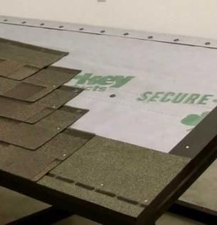
About
          Thanks for volunteering to serve in Mexico with TKA. Building homes is a
   transformational event for every family we serve and we’re very thankful that you have
                               decided to serve alongside us.
   Our hope is the transformation will not only be economic and social but also spiritual.
  Spiritual transformation starts with intentionally making time to listen and interact with
    the people of Tecate. When we do, we’ll all be continuously amazed by the results.
   The families are not the only ones who will be transformed. Our students (and you) will
  be changed by this trip. Take time to interact with our students and one another as well.
                 God always creates special moments - be looking for them.
      Our goal was to make these plans as simple as possible to free-up time for those
                                meaningful interactions.
            This document contains the plans for building the 2020 Casitas. For “how to
                  instructions” see the “Casitas 2020 – How to Instruction Guide”.

                    For any suggestions or corrections please send an email to
                                    Larry Ells (kool2@pacbell.net) &
                                Rich Ghiossi (richghiossi@gmail.com)
                        Rich Ghiossi and Larry Ells have developed these plans for TKA’s use

1/18/2020                                     Version 3.3 - 01 18 2020                         2
Table of Contents
• Introduction
      • About
      • Guideline and tips
• 4-Day build plan overview
• Work plan summary
• Detailed building plans
• Appendix
    • Material list
    • Nails
    • 2-Day build plan overview

1/18/2020                     Version 3.3 - 01 18 2020   3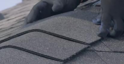
Casa 2019: Guides and Tips
  “How to build your casa without going crazy”

   Our goal with this guide is to make it as simple and as easy as possible to build this new
    Casa. We’ve taken a very basic step-by-step approach to keep the average group from
  becoming overwhelmed with the task at hand. Most groups that build are just like yours,
  high on excitement and somewhat lower on construction experience. And that’s perfect,
these plans have been designed for you! They will help you finish your casa and have time to
     fellowship with the family and your students. As simple as the plans are, we highly
 recommend that you study them before going to Mexico with your students. It’s better to
 be familiar with the plans and processes than to be learning in real-time. To help you better
 understand the plans be sure to check-out the pictures and videos of houses being build in
 previous years (available at www.tka.org/tecate20XX – XX=current year ). A picture is worth
a 1000 words. Another helpful tip is to learn a few basic Spanish phrases. The words below
                                     will get you started.
                                    Helpful Spanish words
Hammer; “Martillo” (mar-TEE-yo)           My name is _______: “Me llamo _______” (May-YAH-mo )
Nails: “Clavos” (KLAH-bos)                Nice to meet you: “Mucho gusto” (moo-choh-goo-stow)
Door: “Puerta” (p’ware-tah)               I don’t speak Spanish: “No hablo español” (No AH-blow )
Window: “Ventana” (Bain-tah-nah)          What’s your name? : “Como se llama?” (ko-mo-say yah-mah)
Help! “Ayu’deme” (ah-you-da-may) Where’s the 1st Aid Kit? “ Donde’ esta el botiquin” (botee-keen)
  1/18/2020                                Version 3.3 - 01 18 2020                                  4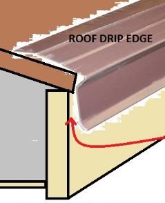
4-Day Build Plan Overview
The plan below provides a general outline of the tasks to be completed each day. This is only a guideline.
Each site will work at different paces on different days. To be most effective, It’s important to keep everyone
working (most of the time), which will require different groups working on different tasks simultaneously.

 • Day One:
       1. Meet the family you’re building for and pray together with everyone
       2. Organize your materials and set up a safe jobsite for the next our days
       3. Frame and install walls 1, 2, 3 and 4
       4. Paint the exterior siding and the trim pieces (siding can be painted before or after it is installed)
 • Day Two:
       1. Finish building all walls
       2. Frame roof: Ridge, Rafters, Blocking, fascia and sheeting
       3. Install rough electrical : Electrical boxes, and wiring
       4. Begin Sheetrocking
       5. Install windows
       6. Start external trim
 • Day Three:
       1. Finish Sheetrock installation
       2. Finish roof: Felt (black paper), sheet metal drip and shingles.
       3. Close in the gable-ends of the house (the triangular panels on the front and rear walls)
       4. Start internal trim
       5. Mud and tape the sheetrock
 • Day Four:
       1. Finish taping and mudding sheetrock
       2. Install front door and lockset
       3. Touch-up external painting
       4. Electrical trim out (switches, outlets, light fixtures and cover plates)
       5. Jobsite cleanup
       6. House Dedication Ceremony
 1/18/2020                                               Version 3.3 - 01 18 2020                                 5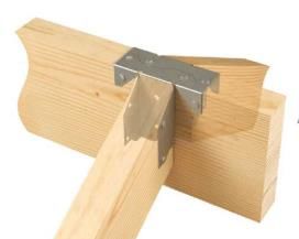
Work plan summary 1of 3
1.     ORGANIZE THE MATERIALS: (Everyone) When you get to your site, the lumber and materials are
       usually stacked on the cement slab. You need to clear the slab because that’s where you’ll be laying
       out and building the walls. This is a good job for everyone! Sort the materials by dimension and
       also by length (i.e., stack the 2x4 studs(8’) in a pile, and the 2x4x20 in a separate pile, siding,
       sheetrock, etc.). Be sure to keep the siding accessible – it will be used early on day one.
2.     LOCATE THE NAILS/HARDWARE: (1 Person) Have someone talk to the Mexican family and find out
       where the nails are and the hardware box. Refer to hardware list for specifics.
3.     SET UP SHOP: (2-3 People) Put the generator in a safe location from which 3 cords can be run to
       any spot in the project (typically it is near the chop saw stand).
4.     PAINT THE EXTERIOR WALL PANELS: (3-6 People) Have the paint crew start painting the 4’x8’ siding.
       Once the siding is finished, start painting the external trim (1”x4” wood)
5.     CUT THE STUDS: (2-3 people) Have the cutting crew start cutting 2x4’s to length (92 ½”) using 8’
       2X4’s (you’ll need about 50). Check the measurements of the studs. Some maybe are precut to this
       length. Save the 20’ and 16’ 2x4 for the top plates and sill plates.
6.     LAYOUT THE WALLS AND FRAME: (Layout 1-2 People, Framing 8-12) Start with a couple of student
       who will serve as your layout group for the first 3-4 walls. Once the layout of the first wall is
       complete use most of the team (10-14 students) to build the wall, install siding and raise the wall.
7.     CUT THE RAFTERS: (2-3 People) As soon as all the studs are cut, have the crew start cutting the
       rafters (you’ll need 26 total). Use the 10’ long 2x4. DON’T CUT THE 16’ or 20’ 2X4’s FOR RAFTERS.
       You’ll need these for the top plate, and fascia.

1/18/2020                                  Version 3.3 - 01 18 2020                                           6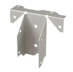
Work plan summary 2 of 3
8.     BUILD RIDGE POSTS AND RIDGE BEAM: (2 people) Have a crew cut and assemble ridge posts as per
       plans. Locate the 2x8x22’ (or the two 2x8, one 10’ or one 12’) the ridge beam.
9.     RIDGE/RAFTER/BLOCK/FASCIA INSTALLATION: A substantial sized group can be installing rafters and
       the blocks between them. AFTER the blocks, install the 2x4 fascia.
10.    OSB ROOF DECK INSTALLATION: (A crew of 4-6) Crew should be wearing shoes that aren’t too
       slippery.
11.    ROOFING INSTALLATION: (6-8 People) Roofing install starts with the felt paper stapled in
       place…Don’t install this if you aren’t going to install shingles on the same day (wind over night may
       rip the sheeting off the roof)…Many a roofing crew has come back in the morning expecting to
       shingle over their previously installed felt paper, only to find the felt paper littering the hillside. If
       there is any rain or dew on the felt paper, it’s very, very slippery…
12.    ROOF/GABLE OSB CUTTING: Have a crew of 2 ready to hand out OSB to your roofing crew. Cut as
       much as you can on the ground.
13.    ELECTRICAL BOX AND ROUGH WIRING INSTALLATION: (3-4 People) This is a job to delegate to some
       go-getters. Have them locate all the electrical parts and install the outlet boxes as per electrical
       plans. You can have a secondary crew drill the holes for the wiring through the framing.
14.    CUT OUT SIDING FOR WINDOWS AND INSTALL WINDOWS: Drill a pilot hole each corner of the
       window openings, and then connect the dots with a Sawzall! Have 2 or 3 people work together on
       this. The windows are installed on top of the plywood with 8d nails or screws through the flange…
       use caulking under the flange. Have somebody on the team on the opposite side of the wall for
       safety.

1/18/2020                                    Version 3.3 - 01 18 2020                                               7
Work plan summary 3 of 3
15. TRIM INSTALLATION: (2-4 people) The 1x4 trim (now painted) can be installed in the following
order: Trim out the windows, put the horizontal trim on the 16’ long walls below the triangle
plywood to cover the seam, install the vertical trim on the siding seams and the corners as per
plan. (Leave the door trim for the door installation crew)
16. SHEETROCK INSTALLATION: (6-8 People): Don’t start until the wiring is run to the boxes! Sheet rock
installation starts with the bedroom ceilings and works down the walls and out to the main room.
Tape and mud the sheetrock as soon as the bedrooms are complete with sheetrock and metal
corners.
17. WINDOW TRIM (INSIDE): (2-3 People); Cut and install the casing and trim aound the windows.
18. CRIPPLE STUDS/OSB INSTALL FOR GABLE ENDS OF HOUSE: (2 People) Angle-cut 2x4 for backing the
OSB triangles on the 16’ long walls at the top.
19. ELECTRICAL TRIMOUT: (2-4 People) After the sheetrock is taped and mudded, install the light
fixtures, light switches, outlets, circuit breaker box (if supplied) and install all the light bulbs and
cover plates.
20. FRONT DOOR INSTALLATION: (2-3 people) After the sheetrock is 90% complete, install front door as
per door installation guide. Install and test the lockset and give the keys to the site leader.
21. PAINT TOUCH-UPS: (2-3 PEOPLE)This is a good job for a couple of people that are getting a little
burned out…it’s not hard and involved. The fascia should be painted on the outside and bottom
edge. And the nails on the trim can be painted over. It’s a good idea to paint over exposed knots in
the siding and on any unpainted cut ends of the trim.
22. JOBSITE CLEANUP: (1-3 People) This is a very overlooked and very necessary job. This can be done
at all times especially toward the end of the workday. It allows others to work more safely and
efficiently.
1/18/2020 Version 3.3 - 01 18 2020 8Detailed Building Plans
Details Page Details Page
❑ Floor Plan 10 ❑ Ridge Beam Installation 25
❑ Walls 1 & 2 framing 11 ❑ Roof Rafter and Ceiling Joist 26
❑ U-Channel Construction 12 ❑ Roof Blocking and Fascia 27-31
❑ Walls 1 & 2 with Channels 13 ❑ Gable Installation 32-33
❑ Walls 1 & 2 Siding 14 ❑ Window Installation 34
❑ Wall 3 Framing & Siding 15-16 ❑ External Trim 35
❑ Wall 4 Framing & Siding 17-18 ❑ Roof Sheeting and Drip 36-38
❑ Wall 5 Framing 19 ❑ Roof Shingles 39
❑ Wall 6 Framing 20 ❑ Rough Electrical 40-41
❑ Top Plate Installation 21 ❑ Sheetrock layout 42-45
❑ Ridge Post and Ridge Beam 22 ❑ Finish Electrical 46-48
❑ Ridge Beam bracket ass. 23 ❑ Window & Door Trim (int) 49-50
❑ Ridge Post Installation 24 ❑ Door Installation 51-52
1/18/2020 Version 3.3 - 01 18 2020 9Floor Plan
20’
Top Plate
Window Door
16’
Opening
15’ 5”
8’ 1”
Opening
Window Window
Notes:
1. You’re free to move the windows or external door locations, but you will need to make those plan changes on
site. Changing the plans is not recommended, they will have a negative impact on our overall program.
2. Measure the slab to ensure its 20’x16’. If it is NOT, you will need to make adjustments, but please do not
make any other changes.
1/18/2020 Version 3.3 - 01 18 2020 10Walls 1&2
Top Plate
California
Corners
92 ½”
“A” is for view
reference only
California
California Bottom Plate
Corners
Corners
Sheetrock side (inside)
Notes:
1. Use 13 studs (per wall) 92 ½” and top and bottom plates
(4 total – 2ea/wall) to exactly 20’
2. Drill holes in the bottom plate for foundation bolts
3. Layout studs on 24” centers Siding side
4. Create California corner on each end. Make sure the flat
side of the California corner is on the inside (sheetrock Sheetrock side
side).
5. Nail top and bottom plates to studs using 16d nails California corner (example)
1/18/2020 Version 3.3 - 01 18 2020 11U–Channels (4 X)
Side View
.
Nails
.
92 ½”
.
Nails
.
Bottom of studs are all flush
Notes:
1. Construct “4” U-Channels (one for each of walls 1,2,3 & 5)
2. Use 3 studs 92 ½” for each channel
3. Carefully align studs (stud bottoms should be all flush with one another)
4. Nail sides with 16d nails
1/18/2020 Version 3.3 - 01 18 2020 12Walls 1&2 with Channel
99” AA
92 ½”
“A” is for view
reference only
Top Plate
Sheetrock side
AA
Notes:
1. Install pre-constructed U-channel into walls 1 & 2 as 99”
shown
2. Make sure the channel’s flat side is on the sheetrock
side (inside) of the wall
1/18/2020 Version 3.3 - 01 18 2020 13Walls 1&2 with Siding
92 ½”
Notes:
1. Square wall before nailing siding
2. Nail siding with overhang on bottom of the wall, aligning the top of the sheet with the top of
the top plate. Nail on 8 to 12” centers
3. Starting at one end add one sheet at a time
4. If ‘tongue and grove’ siding, ensure that the ‘tongue and grove’ overlap
5. Nail siding with 8d nails on 8-10” centers
1/18/2020 Version 3.3 - 01 18 2020 14Wall 3
Top Plate
Center line
10 ¼”
92 ½”
Cut list:
(check window/s dimensions before
cutting) Opening is designed to be
½” larger than window on all sides
4ea: 36 ½”
2ea: 42 ¾” U-Channel
2ea: 10 ¼”
Notes:
1. Measure slab first, then cut 2, 16’ 2x4. The length should be ~185” (15’ 5”) for top and bottom plates
2. Drill holes for foundation bolts (‘hold downs’)
3. Layout the wall starting from the center of wall (92 ½” for either wall end)
4. Center the pre-built U-Channel on the wall’s center line
5. Build the rest of the wall using 8 full length studs and frame the windows opening using the material from
the cut list
1/18/2020 Version 3.3 - 01 18 2020 15If you are using the optional
Wall 3 metal ridge post plate don’t
nail the siding in this areas yet.
Top Plate Center line
92 ½”
U-Channel
Notes: Nail sheets 2” from the edge
along the center line
1. Square wall before nailing siding
2. Nail 2 siding sheet to the center of the wall (grey area above)
3. Make sure the siding overhangs on bottom of the wall, aligning the top of the
sheet with the top of the top plate.
4. Nail siding sheeting on 8” to 12” centers
5. Wait to install the remaining siding until later. This will allow more points of
entry into the building
1/18/2020 Version 3.3 - 01 18 2020 16Wall 4
Top Plate
10 ½” 10 ¼”
80 ½”
92 ½”
36 ¼”
Cut list:
(check window and door
dimensions before cutting)
2ea: 80 ½”
1ea: 39 ¼” Door
1ea: 10 ½”
1ea: 10 ¼”
1ea: 42 ¾” Window
2ea: 36 ½”
40 ¾”
Notes:
1. Cut 2, 16’ 2x4 to 185” (15’ 5”) for top and bottom plates
2. Drill holes in the bottom plat for the foundation bolts (‘hold downs’)
3. Start layout from center of wall (92 ½” for either side)
4. Build the wall using 9 full length studs and frame the window and door opening using the
material from the cut list
5. Door opening. Cut out bottom plate after wall is in place and secure to foundation
1/18/2020 Version 3.3 - 01 18 2020 17Wall 4 See Note on page 16
Siding sheets
92 ½”
Notes: Nail sheets 2” from the edge
1. Square wall before nailing siding 40 ¾” along the center line
2. Make sure the siding overhangs on bottom of the wall, aligning the top of
the sheet with the top of the top plate Nail 2 siding sheet to the center of
the wall (grey area above)
3. Nail siding sheeting on 8” centers
4. Wait to install the remaining siding until later. This will allow more points of
entry into the building
1/18/2020 Version 3.3 - 01 18 2020 18Wall 5
10 ¼” 10 ¼”
Door Door
Opening Opening
92 ½”
Cut list:
(check window and door
dimensions before cutting)
4ea: 80 ¾” U-Channel Centered on Wall
~ 92 ½”
2ea: 35”
2ea: 10 ¼”
Notes:
1. Cut 2, 16’ 2x4 to 185” (15’ 5”) for top and bottom plates
2. Start by placing the pre-built U-Channel in the center of the wall (flat part of “U” should face wall 3)
3. Place all the full length studs (10 total) and nail (studs and channel)
4. Frame out door openings using the material from the cut list.
5. After wall is in place, secure (nail) to walls 1&2, then secure to foundation with concrete nails provided.
6. Cut out the bottom plate of the door openings after wall is in place and secure
1/18/2020 Version 3.3 - 01 18 2020 19Wall 6
Double stud
Wall 3 Wall 5
Side Side
92 ½”
Double stud
Notes:
1. Measure distance between walls 3 & 5. If not 97”, adjust as necessary
2. Start layout from one end
3. Layout studs on 24” centers (except for the far right) Install two studs on the
right end
4. Then secure to foundation with concrete nails provided.
1/18/2020 Version 3.3 - 01 18 2020 20Top Plates
Cut list:
(check dimension on building before cutting)
6ea: 94 ¼”
2ea: 97” 97”
2ea: 130 ½”
2 6 4
94 ¼”
Wall 3 Wall 5
Wall 4
1
Second Top Plate
20’
3 7 5
132 ½” ”
Wall Top 94 ¼”
Plate
Wall
Notes:
1. Make sure walls are square, straight and plumb before nailing
2. Install 2nd top plates in order (as shown above) starting with “1” through “7, then add others.
3. Use a 20’ 2x4 for top plate number “1”.
4. Note top plate number “1” it is not supported over the living room area
1/18/2020 Version 3.3 - 01 18 2020 21Ridge Post New
Ridge Post Construction
Make 3 ridge Optional Bracket
post sets On top of Post
16 ½”
Add plate to
Side are aligned 18 ½”
2 of 3 post
(Flush with one
(optional)
another)
Bottom of 2x4’s are all flush
Notes:
1. Cut 3 – 2x4’s to the dimensions above (make 3 sets)
2. Sandwich and carefully align three 2x4’s
3. Optional: Add 6’ metal plate (picture on left) to one side of post on two post only (the middle post can
not use the plate)
4. Optional: Hurricane bracket at top of tops (pictured on right)
Ridge Beam
2”x 8” x 22’
Notes:
1. Ridge beam is 22’ long. It’s cut from the 24’x 2”x 8” beam.
2. If you don’t have a 22’ or 24’ beam, see the appendix for how to use a 8’ and 12’ spliced together
1/18/2020 Version 3.3 - 01 18 2020 22New Ridge Beam Brackets
2”x 8” x 22’
A B C D E F G H I J K
12¾” 23¼” 24” 24” 24” 24” 24” 24” 24” 24” 23¼” 12¾”
Notes:
1. Mark bracket locations on ridge beam, positions A-K
2. Dimension from the end of the beam to location A is 12 ¾” end to center (A). It’s the same
dimension for K to the end of the beam (12 ¾”).
3. Note the distance between A & B and J & K are 23 ¼” which is different that the dimensions of
(B-J) which are 24”, center to center.
4. Double check all measurement before installing bracket
5. Install brackets on both sides of ridge beam in locations A- K (22 brackets – 11 on each side)
Center Line
Bracket (22) Center Line Brackets Installed
1/18/2020 Version 3.3 - 01 18 2020 23Ridge Post Installation “Top down view”
Wall 3 Wall 4
1 2 3
Ridge Post (optional)
flat plate is installed on
the outside and under
siding (both ends 1 & 3)
Notes:
1. Install the 3 Ridge Post on top of the 2nd / middle top plate
1. Position Ridge Post 1 (4 ½”side) flush with outside edge of the top plate and in the middle of wall 3
2. Position Ridge Post 3 (4 ½”side) flush with outside edge of the top plate and in the middle of wall 4
3. Position Ridge Post 2 directly above wall 5. Center the post 2 by running a line between post 1 & 3
2. Make sure Ridge Posts are plumb before securing
3. Toenail and/or use right angle metal brackets to secure Ridge Posts to top plate
1/18/2020 Version 3.3 - 01 18 2020 24Ridge Beam installation
New
“Top down view”
12”
12”
Notes:
1. Rest the ridge beam on top of the ridge post and then adjust into to position. Starting at one end,
make sure the first post is plumb and the beam is positioned exactly 12” from the outer edge of the
post to the end of the beam and then tack beam to the post.
2. Repeat the process on the 3rd post (beam over hang should be also 12”).
3. Move to the center post once the beam is tacked to the 1st & 3rd posts. Repeat the process, making
sure the first post and third posts are plumb and then tack beam to 2nd post.
4. Finally beam secure with screws or nails
1/18/2020 Version 3.3 - 01 18 2020 25Roof Rafters & 10’
Ceiling Joists
Notes:
1. Cut 26 Roof rafter from 10’ 2 X 4” with 12* angle on one end
2. Make sure all roof rafters are the same length
3. Cut 7 ceiling Joist from 16’ 2X4’s to exactly 16’ (or to the measured width between walls 1 & 2).
Wall 3 & 4 gable supports 3 ½”
4x - Short Block
Notes:
1. Cut 8 blocks to support the Wall 3 & 4
gable siding 4x – Long Block
2. You will use these on page 32
1/18/2020 Version 3.3 - 01 18 2020 26Roof Rafter and Ceiling Joist Installation - Step 1a
“Side view – as looking at wall 1 from the outside of house”
Ridge Beam
All Dimension are Center to Center
23 ¼” 2’
24” 24” 24” 24” 24” 24” 24” 24” 23 ¼”
Roof
Rafters
A B C D E
Add 2x4 C
(easier to
nail Joist) 2nd Top Plate
Ceiling Joist
Top part of Wall 1
Notes:
1. Before installing, mark both top plates on walls 1&2. Also mark the ridge beam if you haven’t already.
2. Install rafter A (front side), then the opposite side rafter A back side) - (This process of installing front and
then back roof joist should be followed when installing all roof rafters).
3. After installing roof rafters A, install ceiling joist A. You will repeat this pattern of installing roof rafters
followed by ceiling joists for locations B, C, D and E.
4. Notice all the ceiling joists should be nailed to the side of roof rafters except for ceiling joist A (which is offset
by 3 ½” between the rafter and joist). To make nailing ceiling joist A easier, install a 2x4 on top of the top
plate and nail the ceiling joist A to it.
5. All roof rafters will be installed using a metal bracket. See diagram on page 29 for specific bracket details.
1/18/2020 Version 3.3 - 01 18 2020 27Roof Rafter and Ceiling Joist Installation - Step 1b
New “Side view – as looking at wall 1 from the outside of house”
Ridge Beam
All Dimension are Center to Center
23 ¼”
½” 2’
24” 24” 24” 24” 24” 24” 24” 24” 23 ¼”
½”
Roof
Rafters
A B C D E F G H I J K
C
Ceiling Joist
Top part of Wall 1
Notes:
1. Once you have installed rafters A-E and their corresponding ceiling joists, then install the remaining roof
rafters and celling joists.
2. Start by installing rafters F, using the same process used on rafters and ceiling joist A-E
1/18/2020 Version 3.3 - 01 18 2020 28Roof rafter and ceiling joist Installation
Bracket details
Roof Rafters Brackets
Joist location - right side (example)
Notes:
1. Install bracket on all rafters / joist combinations A-J
2. Mount brackets on inside of wall / building
1/18/2020 Version 3.3 - 01 18 2020 29Roof fascia and outer roof rafters Installation
132 132
A ” B ”
1 3
Wall 4
Wall 3
2 4
Wall 1
C D
Notes:
1. Install Roof rafter fascia, A-D
2. Then install rafters, 1-4
1/18/2020 Version 3.3 - 01 18 2020 30Roof Blocking Installation
132” 132”
Cut list:
(check dimension between
rafters before cutting blocks) A B B B B B B B B A
20 Blocks from 2x4’s
- 4ea: 21 3/4” (A’s)
- 16ea: 22 1/2“ (B’s)
Wall 3
Wall 4
Notes:
1. Blocks can be installed
on each side
independently
A B B B B B B B B A
Wall 1
1’ ¾” 1’ ¾”
1/18/2020 Version 3.3 - 01 18 2020 31Gable Siding
Gable Left side
24 3/8”
4”
Smooth Side
7’ 11”
Notes:
1. Cut 2ea (Left sides for each end of building)
2. Cut both from one sheet of roofing (OSB material) or you can also use the siding material (but
this will be more difficult to cut if you want the grooves to line-up)
3. When cutting make sure the smooth side of the OSB is up (the smooth side faces out)
Gable right side
24 3/8” Smooth Side 4”
7’ 11”
Notes:
1. Cut 2ea (right sides for each end of building)
2. Cut both from one sheet of roofing material (OSB material)
3. When cutting make sure the smooth side of the OSB is up (the smooth side faces out)
1/18/2020 Version 3.3 - 01 18 2020 32Gable Construction
2X8
Notes:
1. First Install the gable blocking (short and long) in 8 locations. 2 sets (short
and long) on left and right sides of wall 3 and 4.
2. Nail roof sheeting using 8d nails
1. Top along the ridge rafter
2. Bottom to the top plate
3. To the short and long blocking
3. Install the smooth side of the OSB facing out
1/18/2020 Version 3.3 - 01 18 2020 33Window Installation
Notes:
1. Drill holes in the window frame as shown below (2
holes on the both sides of window) at positions “A”
2. Place the window into the opening making sure it fit
easily (there should be about a ¼” gap around the
window, which is typical). A A
3. Also make sure the window is right side-up (drain holes
are on the bottom side and on the outside of the Window
window) and that the outside face on the window
frame is flush with external side of the siding.
4. Use screws to attached the window to the wall in 4
places (“A”) making sure the window is square and A A
plumb. Do not over tighten the screws. This could pull
the window out of plumb and break the window.
External Siding
Window Drains
Window Hole Detail Holes
Drill through the side of
the window frame in 4 A
locations
1/18/2020 Version 3.3 - 01 18 2020 34External Window Trim
Step 1 Step 2 Point A Step 3
C
Window B
A
D
External Siding
Notes: Notes: Notes:
1. Measure length A & B. 1. Caulk the back side of the trim 1. Center and install top and
Measurements should be with a bead along all the edges bottom trim using 8d nails
about ½” less than the height 2. Install left and right side trim 2. Caulk the back side of the
of the window frame. This pieces using 8d nails making trim with a bead along all
allows for the trim to cover sure the trim is covering the the edges
the gap between the window window frame by at least ¼” 3. Make sure caulk fills the
and the siding. on both sides. slots in the siding above the
2. Using rough cut trim material 3. Measure C and D dimensions. trim (see points A above)
(1”X4”) cut left and right trim 4. Using rough cut trim material 4. Run a bead of caulk
to dimensions A & B. (1’X4”) cut top trim to between the edge of the
dimension C Plus (+) 4” window and trim
1/18/2020 Version 3.3 - 01 18 2020 35Roof Sheeting Layout
Wall 2
Cut List:
4ea: 4’ x 7’
Row 1
4ea: 4’ x 3’ (cut 2 per sheet)
2ea: 2’ x 8’
4ea; }
2’ x 7’
cut from 3 sheets
6ea: 4’ x 8’ (no cutting required) Row 2
Ridge Beam Row 3
Wall 3 Row 3
See Note 6
Row 2
Row 1
Notes: Wall 1
1. Start with Row 1 on one side of building, positioning and nailing all three sheets
2. Install row 2 and then row 3 all on the same side
3. Move to the opposite side installing Row 1, then row 2 and 3.
4. Nail using 8d nails, 8” centers
5. If you have a gap along the ridge beam, either cut filler strips or double paper the ridge area.
1/18/2020 Version 3.3 - 01 18 2020 36Roofing Paper
Row 2
Row 1
Notes:
1. After all the roof material (OSB) is nailed the next step is to cover both sides with roofing felt (black paper).
2. Start by rolling out and tacking the paper across the bottom of the roof (row 1).
3. Progress by adding paper one row at a time until the one side is completely covered. Remember to overlap
by at least 30% as you add rows. Typically the paper has a line to help gauge overlap
4. Complete the second side, starting at the bottom and moving up the roof as you did on the first side.
5. At the ridge, overlap the paper from one to the opposite side
1/18/2020 Version 3.3 - 01 18 2020 37Roofing Drip Edge
Drip Edge Detail
Paper
Small Gap
fascia
Row 2
Drip Edge
Notes:
1. After all the roof is complete covered with felt the next step is to add the drip edge around all
the roof edges.
2. Nail the drip edge using 8d nails staring near the end and then every 24’ to 30”
3. When adding additional piece, overlap the drip edges by at least 6”
4. Note: Once you have installed felt and drip on one side of the roof you can start shingling that
side.
1/18/2020 Version 3.3 - 01 18 2020 38Roofing Shingles
Shingle Detail
Shingles
Right
side up
Ridge Beam
Bottom Row
Ridge Cap Detail
Row 2
Cut line
Notes: Right side up covering first row First row upside down
1. On the row first only, apply two shingle layers. First lay the shingles upside down as shown above. Once
completed then install the second layer right side up .
2. When starting additional rows, offset the start so that the joints in the singles don’t line-up.
3. Continue this process across and up until each side of the roof is completely covered.
4. On the top, cut shingles into three piece and apply to as shown in diagram above. Before using cutting full
shingles,,
1/18/2020
use the partial sheets that were cut-off the sides. Save the full shingles.
Version 3.3 - 01 18 2020 39Wires in diagram represent Rough Electrical - Plug Circuit Power In
functional connections not
actual wire routing Breaker Box
Wall 2
Wall 3 Wall 4
Notes: Wall 1
1. Mount electrical breaker box and receptacle (plug) boxes. Layout /mark path of wires
2. Drill holes ( ¾”) in studs and rafters as needed (place hole in middle of the studs)
3. Run wire between receptacle (plug) boxes
4. Strip wires ( ½”) and bend into box. Plugs can be wired once sheetrock is installed
1/18/2020 Version 3.3 - 01 18 2020
40Wires in diagram represent Rough Electrical - Lighting Circuit Power In
functional connections not
actual wire routing Breaker Box
Wall 2
48” Porch Light
Light
Light
Switch
Wall 3 Wall 4
Light
Run wire across
tops plates Power leg
Light
48”
Switch leg
Notes: Wall 1
1. Mount electrical boxes (lights and switches). Layout /mark path for wires.
2. Drill holes ( ¾”) in studs and rafters as needed (place hole in middle of the studs)
3. Run wire to lights and switches
4. Strip wires ( ½”) and bend into box. Installed the lights and switches once the sheetrock installed
1/18/2020 Version 3.3 - 01 18 2020
41Sheetrock Step 1 - Ceilings in Bedrooms
Wall 2
Electric Box
48” X 96”
Cut list:
(check dimensions before
cutting sheetrock)
2 sheet 44” X 96”
44” X 48”
Wall 3 Wall 4
44” X 96”
Electric Box
48” X 96”
Notes: Wall 1
Full Sheet
1. Install full sheets first - (1) in each bedroom
2. Cut out area for electrical box (light) – on the 44’’x96’’ sheet
Partial Sheet
3. Screw sheet to ceiling joists on ~ 8” centers.
Electrical box
1/18/2020 Version 3.3 - 01 18 2020 42New Sheetrock Step 2 – Walls
Sheetrock Orientation: Wall 2
H = Horizontal
3 H 8 H
Sheetrock ledger:
Measure first:
Sheetrock to be Cut to 4’ x ~89”
installed in this step
1 Wall 5
Sheetrock cut areas Cut around openings
after installing
H 4
Wall 6 9
Wall 3 Wall 4
H
H
5
Measure first:
Cut to 4’ x ~89”
2
Cut around openings
after installing
6 H 7 H
Notes: Wall 1
1. Install bedroom ceiling sheetrock before hanging any bedroom wall sheetrock
2. Raise sheetrock off cement floor by ~1/2” off the slab (using shim)
3. Nail sheet on 8” to 12” centers along top & bottom and along all studs
4. Start with installing 4 sheets in position 1 & 2. All other sheets (positions 3 – 9) can be installed
1/18/2020 without any cuts (use full sheets) Version 3.3 - 01 18 2020 43New Sheetrock Step 3 – Partial sheets (walls)
Sheetrock Orientation: Wall 2
H = Horizontal
Sheetrock ledger:
Rough Cut to 5’ 10 12
H H Measure first: 14
Sheetrock install Cut to 4’ x ~56”
Previously
Sheetrock to be
Wall 5 Measure first:
Cut around openings
Cut to 4’ x ~62 ½”
installed in this step after installing
Sheetrock cut areas
Wall 6 Cut around door and
Wall 3 window opening after
Wall 4
installing.
H
Rough Cut to 5’
Cut around openings
after installing
11 13
H H
Wall 1
Notes:
1. Recommend to install in order. Starting with 10 progress through 14
1/18/2020 Version 3.3 - 01 18 2020 44New Sheetrock Step 4 – Partial sheets(walls)
Sheetrock Orientation: Wall 2
H = Horizontal
Sheetrock ledger:
Sheetrock install
Previously
Sheetrock to be
Wall 5
installed in this step
Measure first:
Cut to size
Install horizontality
Wall 6
Wall 3 Wall 4
H
Note A: Install
sheetrock on either side
of wall 6 after all the
other sheetrock in the
bedroom has been
installed
Notes:
Wall 1
1. Cut and install remaining sheet
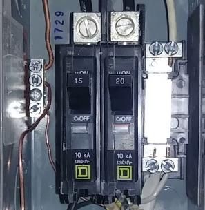
1/18/2020 Version 3.3 - 01 18 2020 45Electrical (Breaker) Box
Power In
(Power Leg)
Black White
Grounding Lugs
Notes:
1. Connect the black wire from power leg
to the input side (top) of the each
breaker.
2. Connect the white wire from the power
leg to the to the common plate as shown Common
3. Connect the black wire of the plug circuit Plate
to the output side of the breaker. Do the
same for the light circuit but to the other
breaker.
4. Connect the white wire of the plug and
switch circuits to the common plate as
shown.
5. Connect all the grounds to the Lights - white
grounding lugs as shown House Circuits Plugs - white
Plugs - black
Lights - black
1/18/2020 Version 3.3 - 01 18 2020 46Finish Electrical - Lighting Circuit
Light Box Connections Switch Box Connections
Power Out
Switch Leg
White Wire
Power In
Ground Wire
Notes: Notes:
1. Connect the black wire from power leg to the 1. Connect the black wire from the switch leg
white wire on the switch leg to the switch (gold screw)
2. Connect the white wire from the power leg to 2. Connect the white wire from the switch leg
the light fixture (silver screw) to the switch (silver screw)
3. Connect the black wire of the switch leg to the 3. Connect the ground wire to the switch
light fixture (gold screw) (green screw)
4. Connect ground wires (bare copper wire)
1/18/2020 Version 3.3 - 01 18 2020 47Finish Electrical - Plug Circuit
Plug Connections – daisy chain Plug Connections – end
White wires
Black wires Pigtails
Power In
Power In Power Out
Notes: Notes:
1. Make-up (3) pigtails 6” long. (1) black, (1) white 1. Connect the white wire from the power leg
and (1) ground (copper wire) to the plug (silver screw)
2. Connect together the (2) black power wires 2. Connect the black wire of the power leg to
with the black pigtail the plug (gold screw)
3. Connect together the (2) white power wires 3. Connect the ground wire of the power leg to
with the white pigtail the plug (green screw)
4. Connect the pigtails to plug (black to gold
screw, white to silver screw and ground to
green screw
1/18/2020 Version 3.3 - 01 18 2020 48Indoor Window Trim – Part 1
Step A Step B Step C
C
A B A B A B
D
Sheetrock
Notes: Notes: Notes:
1. Measure width from 1. Install left and right side 1. Install top and bottom trim
sheetrock (outside surface) trim using 8d nails using 8d nails
to window frame (~3 ½”) 2. Measure C and D 2.
2. Cut width (dimensions from dimensions.
step 1) from the OSB 3. Using the OSB material
material to length of ~4’ from step 2 (Step A) cut C &
(cut 4 pieces) D to the measured lengths
3. Measure length A & B.
4. Using the material from
step 2 cut A & B to the
measured lengths
1/18/2020 Version 3.3 - 01 18 2020 49Indoor Window Trim – Part 2
Step D Step E Step F
C
Window
A B
D
Sheetrock
Notes: Notes: Notes:
1. Measure length A & B in 1. Measure C and D 1. Center and install top and
inches. dimensions. bottom trim fascia using
2. Using the pine trim 2. Using pine trim material finishing nails
material (1’X3”) cut left and (1’X3”) cut top trim fascia to
right trim fascia to dimension C.
dimensions A & B. 3. Using pine trim material
3. Install left and right side (1’X3”) cut bottom trim
using 8d nails fascia to dimension D Plus
(+) 2”
1/18/2020 Version 3.3 - 01 18 2020 50Front Door Installation
Notes:
1. Cut out bottom plate (2x4) of door opening and sweep
area before installing door.
2. Remove all packing materials from the frame of the pre-
hung door before starting.
3. Insert your pre-hung door into the house door opening,
E F
aligning the door frame, flush with the inside and outside
walls.
4. Insert shims along the top of the door frame at location E A
C
&F to set the door. This will help hold the door in place
until the screws are installed. Once the shims are tightly
installed, make sure the door frame is still flush with the
inside and outside walls.
5. Drill holes ( ¼”) through the door frame into the 2x4 house
framing at locations A-D, then using 3” screws anchor the
door (lightly) to the house’s door frame.
6. Using a level, plumb the door on both sides (door frame B D
on sides AB and CD exactly 90* to the floor) without
stressing the door frame. You may need to loosen the
screws slightly to achieve this task.
7. Once the door is plumb, insert shims tightly between the
door frame and building to secure the left and right sides
of the door frame.
8. Tighten the screws A-D to secure door to the house. 1. Install the door locks per the packaged
Double check that the door is still plumb. instructions
9. Test the door to make sure it opens easily, if you have an
issue seek experienced help.
1/18/2020 Version 3.3 - 01 18 2020 51Front Door Trim Installation
Outside Inside
Sheetrock
Siding
Notes: Notes:
1. Using rough cut trim material (1”X4”) 1. Using pine internal trim, measure and
measure and install as shown. install as shown.
2. The door side of the trim should be 2. The door side of the trim should be
positioned in the middle of the door frame’s positioned in the middle of the door
edge. frame’s edge.
3. Caulk all trim, in the same matter as
describe for the external window trim
1/18/2020 Version 3.3 - 01 18 2020 52Congratulations!
You have completed your house build and
made a family very happy!
1/18/2020 Version 3.3 - 01 18 2020 53Appendix
• Material list
• Nails
• 2-Day build plan overview
• Alternate designs
• 2-pieces ridge beam
1/18/2020 Version 3.3 - 01 18 2020 54Materials List
Quantity Size Description Purpose
10 2x4x20 Doug Fir Plates
22 2x4x16 Doug Fir Plates
30 2x4x10 Doug Fir Rafters
1/18/2020
104 2x4x 8 Doug Fir studs (misc)
1 2x8x22 Doug Fir Ridge
20 1x2x8 Pine Indoor Trim
20 4x8x1/2" Plywood Siding
16 4x8x1/2" OSB Roof Sheathing
40 1x4x8 Pine Outside Trim
40 4x8x1/2" Sheetrock Sheetrock
1 compound (redi mix) Mud Sheetrock
2 500' Rolls: Sheet rock paper tape Tape Sheetrock
1 50 lbs Box: Sheetrock nails 1 5/8" nails Nails Sheetrock
16 Bundles: Roofing shingles (>32 sq' / bundle---15-20 year) Shingles Roof
3 Rolls - 30# felt black roofing paper (200 sq"/roll) Felt Roof
1 50# Box: 1" roofing nails Nails Roof
1 Box 1 1/4" construction screws (golds) Roof Brackets Roof
10 2x2 metal drip edge flashing Drip edge Roof
3 36" x 36" sliding window Window Window
7 Gallons of paint - blue Paint Walls
3 2 gallon exterior paint - white Paint Trim
1 Roll (250'); 14/3 Romex electric wire Wire Electrical
4 Plastic nail-in round boxes (lights) Boxes Electrical
10 Single-gang plastic electical boxes (outlets/switches) Boxes Electrical
Version 3.3 - 01 18 2020
1 Double-gang plastic electical boxes (front door switches) Boxes Electrical
3 Single-pole/single-throw electrical switches (lights) Switches Electrical
6 Duplex electrical outlets Outles Electrical
7 Outlet cover plates - single Covers Electrical
3 Switch cover plates - single Covers Electrical
1 Switch cover plates - double Covers Electrical
1 box romex staples (small) Stables Electrical
3 Simple light fixtures Fixture Electrical
1 Porch light Fixtures Electrical
1 Entry door - 36" prehung metal clad Front Door Door
1 Entry lockset with deadbolt Lockset Door
TKA Supplied
22 Ridge beam hangers Metal Ridge
20 Hurricane clips Metal Ceiling joist
2/3 50# Box: 16d vinyl-coated sinker nails Nails Walls / Roof
2/3 50# Box: 8d vinyl-coated sinker nails Nails Walls/Roof
25 1/2 nuts & washers - Hold-down bolts Bolts Walls
55
20 concrete nails Nails Internal Walls
1 Main electrical box w/ 2 - 15 amp breakers Main ElectricalMaterial Usage
Lumber use Reference
20' 2X4X20 (10)
4ea Top / Bottom plates on wall 1&2
3ea 2nd Top plate
1/18/2020
3ea Extra
16' 2X4X16 (22)
6ea Top / Bottom plates on wall 3&4&5
10ea Ceiling Joist
3ea 2nd top plates
2ea Facia
1ea Extra
10' 2X4X10 (30)
26ea Roof rafters
4ea Extras
8' 2X4X8 (104)
71ea Studs (all walls) including U-Channels
2ea Top and bottom plates on wall 6
6ea Window framing (2/ window)
9ea Door framing (3/door)
3ea Ridge post
2ea Gable framing
5ea Blocking (4 blocks / 2x4x8's)
2ea Facia
Version 3.3 - 01 18 2020
6ea Extras
Siding 4'X8'X1/2" (20)
18ea Siding on walls 1-4
1ea Gables
1ea Extras
OSB - roofing 4'X8'X1/2" (16)
15ea Roof sheeting
1ea Extra's
Sheetrock 4'X8'X1/2" (36)
34ea Walls sheetrock
2ea Extra's
56Nails 1/18/2020 Version 3.3 - 01 18 2020 57
Change Log
• V1.0 – 3 13 2019 – First public version
• V2.0
      •     Fixed 2 dimensions
               •   Page 13, Fixed the left end point of the 99” dimension
               •   Page 21, Fixed the top plate dimension from 99” to 97”
      •     Page 25, change the length of roof rafter from 10” to 9’10”
      •     Added Notes to pages 16,18, 23 and 26
      •     Change diagram on page 45
• V3.0
      •     Fixed / enhanced notes on pages 2,4,5,6,7,8,10,28,36,37,39,41
      •     Enhance diagram in page 20,
      •     Ridge beam change to one piece 8” wide and ridge post. Pages 22, 25
      •     Add roof rafter bracket detail to page 23 (new page) supplies by TKA
      •     Change roof rafter cut detail (from 9’10” to 10’) page 26
      •     Add additional ceiling joists on left side (living room), page 28
      •     Change the stud length from 92 ¾” to 92 ½” – pages 6,11-20
      •     Revised sheetrock instructions, pages 43-45 (added one additional page)
      •     Updated the Material List page 55 (added material usage list page 56)

1/18/2020                                           Version 3.3 - 01 18 2020          58
Alternate 2-piece Ridge Beam design
Ridge Post Construction
2 ½”
Make 3 ridge post sets
Add plate to
Side are aligned
2 of 3 post
(Flush with one
(optional)
another)
Bottom of 2x4’s are all flush
Notes:
1. Cut 3 – 2x4’s to the dimensions above (make 3 sets)
2. Sandwich and carefully align three 2x4’s
3. Add 6’ plate to one side of post as shown – Optional (only two of three)
Ridge Beam
2”x 8” x 10’ 16” 2”x 8” x 12’
Notes: Splice support
1. Ridge beam consist of two 2X8’s spliced together – Make sure the total length is exactly 22’ and the joint
cut to exactly 90*. Also make sure the spliced 22’ beam is completely linear (no bend at the splice). With
this splice location, the splice will end between roof rafters.
2. Splice 2x8’s together using two scrap pieces of siding ( from the window cut-outs) with dimensions of 16” x
8” centered on the splice point– one for each side.
3. Use either 8p nails of 2” screws to attached the splices, at least 5 nails/screws on each side of the splice
1/18/2020 Version 3.3 - 01 18 2020 592-piece Ridge Beam installation
“Top down view”
12”
8’ 12”
14’
Notes:
1. Rest the ridge beam on top of the ridge post and then adjust into to position Starting at one
end, make sure the first post is plumb and that the beam is positioned exactly 12” from the
outer edge of the post to the end of the beam and tack beam to the post.
2. Repeat the process on the 3rd post (beam over hang should be also 12”).
3. Move to the center post once the beam is tacked to the 1st & 3rd posts. Repeat the process,
making sure the first post and third posts are plumb and tack beam to 2nd post.
4. Tack with a 2’ screw and final secure with screws or nails
1/18/2020 Version 3.3 - 01 18 2020 60You can also read