CATALOGUE 01|2021 DESIGN & CONSTRUCTION - AC/DC CONVERTER DC/DC CONVERTER DC/AC CONVERTER CUSTOM DEVICES - MTS Elettronica
←
→
Page content transcription
If your browser does not render page correctly, please read the page content below

CATALOGUE 01|2021

DESIGN & CONSTRUCTION
AC/DC CONVERTER   DC/DC CONVERTER
DC/AC CONVERTER   CUSTOM DEVICES

                            1996-2021
1996-2021
             We founded our business in 1996 with the company MULTISERVICE
             snc, owner of the Trademark MTS Elettronica.
             MULTISERVICE designs and manufactures energy conversion devices,
             types AC/DC and DC/DC.
             These devices are used mainly in the industrial and tertiary sectors.
             Over the years, the trademark MTS Elettronica established in
             the domestic and international markets, so the three founders
             shareholders transformed the company in a limited liability company:
             MTS Elettronica Srl.
             The headquarter is in Mantua, near the tollgate junction of Northern
             Mantua (motorway A22 Modena - Brennero). Here we make the
             business, administrative, design and manufacturing activities. Our
             know-how, acquired during the years, allow us to offer technologically

                                                                                            PRODUCT LINE
             cutting edge products, equipped with consolidated technologies, which
             give the finished product a high level of reliability. The great flexibility
             of our production structure allows us to manufacture focused devices,
             satisfying more and more the real needs of the markets and designers.
                                                                                            DC CURRENT
             MTS Elettronica Srl develops any activity concerning R&D of its devices,
             guaranteeing mastery of product, constant service, and an increasing
             growth of the quality of our devices. One of the main advantages of
             MTS Elettronica Srl is flexibility, allowing fast answers to the user and
             customized devices according to any need. Thanks to the company
             organisation and the know-how acquired over the years, we are able
             to manufacture CUSTOMIZED devices, which are the foundation of our
             know-how of constant growth.
             APPLICATIONS FIELDS
             •   Oil & Gas
             •   Electric Plant
             •   Hydroelectric Plant
             •   Transports
             •   Industrial Procedures
             •   Technological System
             •   Hospitals

            AN ISO 9001:2015 CERTIFIED COMPANY

                                                                                                           3
PRODUCT LINE | DC CURRENT PRODUCT LINE | DC CURRENT
IGBT SINGLE BRANCH RECTIFIER TYPE COMPACT ECOLINE RCK5U IGBT SINGLE BRANCH RECTIFIER TYPE COMPACT1-3MCH ECOLINE
AC/DC MODULE TYPE COMPACT ECOLINE RCK5U TYPE COMPACT1-3MCH -ECOLINE
NOMINAL VOLTAGE with 1Ph supply 24 48 110 NOMINAL VOLTAGE with 1Ph supply 24 48 110
CURRENT RANGE with 1Ph supply 5 ÷ 60A CURRENT RANGE with 1Ph supply 10 ÷ 60A
CURRENT RANGE with 3Ph supply 10 ÷ 60A CURRENT RANGE with 3Ph supply 10 ÷ 60A
RIPPLE NOISE (RMS) ≤ 0.5% Vn
RIPPLE NOISE (RMS) ≤ 0.5% Vn
OUTPUT ADJ. VOUT RANGE +/- 5%
OUTPUT ADJ. VOUT RANGE +/- 5%
STABILITY +/- 1%
STABILITY +/- 1%
ADJ. FOLLOWING THE CHANGE Vinp. +/- 1%
ADJ. FOLLOWING THE CHANGE Vinp. +/- 1%
ADJ. FOLLOWING THE CHANGE lLoad +/- 1%
START-UP time 2 sec. ADJ. FOLLOWING THE CHANGE lLoad +/- 1%
230 +/- 10% or 400 +/- 10% START-UP time 2 sec.
NOMINAL VOLTAGE
(1Ph or 3Ph) 230 +/- 10% or 400 +/- 10%
NOMINAL VOLTAGE
FREQ. 50 ÷ 60 +/-7% (1Ph or 3Ph)
INPUT
EFFICIENCY (Typ.) ≥ 90 % INPUT FREQ. 50 ÷ 60 +/-7%
ISOLATION I/O 4kV WITH TRANSFORMER EFFICIENCY (Typ.) ≥ 90 %
2In x 5mS ISOLATION I/O 4kV
AC/DC MODULE-REAR OVERLOAD
Shut down per 250mS - restart aut. 2In x 5mS
OVERLOAD
CURRENT TYPE Constant Shut down for 250mS - restart aut.
MAIN FEATURES PROTECTION
OVP + 10% Vn CURRENT TYPE CONSTANT
•• Power device convertion: IGBT MAIN FEATURES
UVP - 50% Vn PROTECTION
•• Control type: PWM HF •• Power device convertion: IGBT OVP + 10% Vn
OVERTEMP. Shut down. Restart aut.
•• Incoming isolation transformer at mains frequency: OK •• Control type: PWM HF UVP - 50% Vn
•• Electrostatic shield: OK ALARMS SPDT INCOMING MAINS FAILURE LOW VOLTAGE BATTERIES
•• Incoming isolation transformer at mains frequency: OK
5Amp/250Vac GENERAL FAILURE
•• uP of supervision •• Electrostatic shield: OK OVERTEMP. Shut down. Restart aut.
•• LCD with backlit alphanumeric display and LED status WORKING TEMP -10 ……+40°C •• uP of supervision ALARMS SPDT INCOMING MAINS FAILURE LOW VOLTAGE BATTERIES
•• Charging curve for each battery type ENVIRONMENT WORKING HUMIDITY 20 ……90% (NO COND.) •• LCD with backlit alphanumeric display and LED status 5Amp/250Vac GENERAL FAILURE
•• High effeciency STORAGE TEMP. -20 ……+50°C •• Charging curve for each battery type WORKING TEMP. -10 ……+40°C
•• High reliability MARKING CE •• High effeciency
•• Extractable 5U rack-format AC/DC module for quick and ENVIRONMENT WORKING HUMIDITY 20 ……90% ( NO COND.)
PROTECTION DEGREE IEC 60529 •• High reliability
easy assistance thanks to polarized extractable connectors STANDARDS STORAGE TEMP. -20 ……+50°C
EMC EN 61000-6-2 EN 61000-6-4 •• Extractable 5U rack-format AC/DC module for quick and
•• Easy maintenance with access from the front MARKING CE
STATIC CONVERTER EN 60146-1-2 easy assistance thanks to polarized extractable connectors
•• Low output ripple
•• Extended frequency input range Iout= 5÷20Amp NATURAL •• Easy maintenance with access from the front PROTECTION DEGREE IEC 60529
VENTILATION STANDARDS
•• Output overload indication Iout= 21÷60Amp FORCED •• Low output ripple EMC EN 61000-6-2 EN 61000-6-4
•• Acknowledgeable audible alarm DIMENSIONS (W*H*D) mm with handle and rear •• Extended frequency input range
5U rack type 482 x 485 X 221 STATIC CONVERTER EN 60146-1-2
•• Accessed from the rear for I/O clamps and relay alarms card
clamps •• Output overload indication
DIMENSIONS (W*H*D) mm without handle and rear clamps 5U rack type 482 x 425 X 221 •• Acknowledgeable audible alarm PROTECTION DEGREE IP30
APPLICATION FIELDS PROTECTION DEGREE IP20 DIMENSIONS (W x D x H) mm 600 x 650 x 1600
APPLICATION FIELDS
•• Oil & Gas PAINT FRONT PANNEL - INDICATIVE WEIGHT RAL 7035 - 15Kg PAINT RAL 7035
•• Energy •• Oil & Gas
LED STATUS ELECTRICAL MEASUREMENTS ON DISPLAY
•• Process control •• Energy
System ok (green) Output voltage •• Process control
•• Trasport
DISPLAY STATE MESSAGES LED STATUS
•• Security System failure (red) Output current •• Transport
•• Security Rectifier ON System ok (green)
Boost Charge ON (Optional) System failure (red)
DISPLAY STATE MESSAGES MULTIFUNCTION PUSH-BUTTON
FRONT HMI
Acknowledgeable audible alarm Manual Charge ON (Optional)
Rectifier ON
ELECTRICAL MEASUREMENTS ON
External transformer Boost Charge ON (Optional) Overload DISPLAY
rack module
Manual Charge ON (Optional) Battery Mode Output voltage
INPUT OUTPUT
INPUT OUTPUT Overload Low Volt. Batt. Output current
Battery Mode End. Batt. Aut.
Low Volt. Batt. Vout. Rect. Max MULTIFUNCTION PUSH-BUTTON
SINGLE LINE DIAGRAM-BASE End. Batt. Aut. Acknowledgeable audible alarm
Vout. Rect. Max
OPTIONS OPTIONS
UP card for function AUT/MAN BATTERY TEST UP card for function DC EARTHED PROBE (with polarity discrimination +/- ) MCB: input ÷ output ÷ battery Coil circuit breaker tripping Battery reverse control (BRPCU)
UP card for function BOOST & MANUAL CHARGE COMMAND FOR EXTERNAL END DISCH.POWER CONTACTOR (LVBD) UP card for function BOOST & MANUAL CHARGE Aux circuit breaker contact ( S/H) E.P.O (Emergency Power Off)
UP card for function TEMP. COMPENSATION UP card for function TEMP. COMPENSATION End battery discharge power contactor
External Temp. probe (3mt. cables max) End battery discharge power contactor uP card for function: AUT./MAN.BATTERY TEST
4 5
PRODUCT LINE | DC CURRENT PRODUCT LINE | DC CURRENT
COMPACT-PLATINUM 4.0 Industrial1- 3Ph Battery Chargers COMPACT-PLATINUM 4.0 Industrial1- 3Ph Battery Chargers
GENERAL TECHNICAL DATA
DC UPS
ELECTRICAL DATA
IGBT THY
Output voltage Vcc 24 48 110 24 48 110 220
A SINGLE SYSTEM, Input Voltage 1 Ph
3 Ph
230 Vac ± 10%
400 Vac ± 10%
NOT AVAILABLE
THREE DIFFERENT CONFIGURATIONS Entry Frequency
Input Voltage - Icc
50 ÷ 60 Hz ± 5%
≤ 10KA RMS (with standard IEC-nominal main input)
Current Input Distortion THD ≤ 27 (with nominal load)
We present the DC UPS of the COMPACT PLATINUM 4.0 series. These devices are the result of Input power factor 0.80 (With nominal voltage 100% load)
careful research and development carried out by our company, aimed at obtaining maximum I/O isolation 4kV with transformer
reliability and the best performance in the field of direct current emergency power systems.
OUTPUT DATA
The improvements made allow us today to offer a single system that can be proposed in
three different basic electrical configurations with IGBT (chopper) or THYRISTOR conversion Output current Input type 1 Ph 10÷60 Amp
technology depending on the required currents. Input type 3 Ph 10÷100 Amp 100÷500 Amp 10÷250 Amp
2,27 V/cell for VRLA battery type
Floating
2,2 ÷ 2,3 V/cell for VLA battery type
(settable from HMI)
1,4 ÷ 1,5 V/cell for Ni-Cd battery type
Battery charging voltage Boost 2,4 ÷ 2,45V/cell for VLA battery type
DOUBLE (settable from HMI) 1,5 ÷ 1,65 V/cell for Ni-Cd battery type
SINGLE BRANCH DOUBLE BRANCH
PARALLEL 2,35 V/cell for VRLA battery type
BRANCH Manual
2,7 V/cell for VLA battery type
settable from HMI)
Product Code Product Code Product Code 1,7 V/cell for Ni-Cd battery type
1R 2R 2RP Current battery charging (settable from HMI) 1 ÷ In Amp
Current characteristic CONSTANT
Output voltage stability (ref.INPUT MAIN VAR.) 1%
Output voltage stability (ref.LOAD VAR.) 1%
INNOVATIVE SYSTEM CONTROL
Output voltage stability 1%
The SYSTEM CONTROL is now based on an expandable Industrial PLC, characterized
Output ripple RMS 1%
therefore by a very high reliability as well as by a considerable flexibility, it allows to
satisfy a greater number of technical needs and consequent applications. This section, 150% per 5 sec
MAIN FEATURES which constitutes the "intelligent" heart of our system, is now made in a special
drawer located on the inside of the main door of the cabinet and FULLY REMOVABLE ENVIRONMENTAL DATA
✔✔ POWER ELEMENT: IGBT OR THYRISTOR DEPENDING ON thanks to the presence of a polarized connector.
Noise level Ref. EN50091 < 60 dBA (typical value with forced ventilation in operation)
This solution introduces a very important advantage, in fact it is possible to replace
POWER Emi EN 61000-6-2 - EN 61000-6-4
this assembly while hot, with the machine running, without turning off the system.
Operating temperature °C -10………. +40
✔✔ ISOLATION TRANSFORMER ON AC INPUT LINE COMPLETE This is possible as the AC / DC conversion units recognize the loss of communication
with the drawer and set themselves up in "AUTOMATIC SAVE MODE", actually working Storage temperature °C -20………..+70
WITH ELECTROSTATIC SHIELD BETWEEN PRIMARY AND
independently and guaranteeing continuity of operation. Once the drawer has been Relative humidity without condensation < 95%
SECONDARY Ventilation
replaced and the connection re-established, the AC / DC units will return to operate Electronic temperature speed control FORCED
(on AC/DC conversion module)
✔✔ SYSTEM CONTROL WITH INDUSTRIAL PLC under the automatic control of the PLC, resuming normal and complete operation.
Altitude Mt.sl.m. < 1000 (derating according EN62040-3)
✔✔ 7 " TOUCHSCREEN PANEL NEW HMI
The HMI (Human Machine Interface) system has also been renewed, which now MECHANICAL DATA
✔✔ CHARGING CURVE FOR AGM - PB - NiCd BATTERY
includes a touch panel, capacitive, 7” with excellent visibility characteristics, Degree of protection - external Ref. IEC 60259 IP 31 standard - others on request
✔✔ 3 CHARGING LEVELS INCLUDING MANUAL CHARGING mechanical resistance to wear and connectivity with the outside world.
Degree of protection - internal Ref. IEC 60259 IP 20 with open front door and additional protections inserted
COMPLETE WITH SAFETY TIMER MORE SPACE FOR REMOTE CONNECTION RAL 7035 cabinet
Paint
✔✔ HIGH MTBF AND LOW MTTR Finally, a great deal of space was reserved for REMOTE CONNECTION, in fact RAL 7012 roof and base
now it is possible to control, parameterize and manage these systems in absolute Dimensions (WxDxH) mm To be defined according to the condition Iout/Autonomy
✔✔ EASY MAINTENANCE WITH ACCESS FROM THE FRONT safety through the INTERNET network thanks to the standard presence of the WEB IN/OUT cable connections From the front with cable input from below
✔✔ LOW RESIDUAL RIPPLE IN OUTPUT AND ON BATTERIES SERVER function. This has an undoubted advantage that significantly improves the Transportation Base for handling with forklift
maintenance and technical assistance aspects in critical installations. Installation From the floor
(RIPPLE)
APPLICATIONS Accessibility Front
✔✔ 4 FULLY USER PROGRAMMABLE ALARM RELAYS
•• Oil & Gas (petrochemical plants, offshore, pipeline). PROTECTIONS
✔✔ TEMPERATURE COMPENSATION WITH PT100 SENSOR •• Electricity generation (power stations, hydroelectric, transmission, distribution, Input Automatic Circuit Breacker
AND CORRECTION COEFFICIENT (Vel / ° C) SETTABLE BY utilities).
•• Transport (Airports, naval, rail). Output Manual Isolator
THE USER
•• Process control (Mining industry, steel mills, paper production, etc.). Battery Fuses
✔✔ AUTOMATIC BATTERY TEST WITH PROGRAMMABLE •• Plants for desalination and water treatment. General Vout > / Vout< / Max.Temp. / Icc / Incorrect cyclic input
FREQUENCY
6 7
PRODUCT LINE | DC CURRENT PRODUCT LINE | DC CURRENT
COMPACT-PLATINUM 4.0 Industrial1- 3Ph Battery Chargers COMPACT-PLATINUM 4.0 Industrial1- 3Ph Battery Chargers
HMI - HUMAN MACHINE INTERFACE
All information regarding the system operating status is available on the 7 ”color touch screen HMI (Human Machine Interface) operator panel with anti-
reflective and scratch-resistant glass. The HMI is complete with a MODBUS TCP / IP and RTU interface (slave - server) for connection to external centralized
control systems that use the same communication protocol, thanks to which the following functions are made available as standard:
1.1 WEB SERVER
Allows remote control of the system through an INTERNET browser
1.2 WEB MAIL
Allows e-mails to be sent to multiple recipients in case of an abnormal
system
1.3 MANUALS AND TECHNICAL DRAWINGS
Allows viewing of these two types of documents directly from HMI for quick
and hands-on on-site consultation.
HOME PAGE
Where you can find all the information about how the system works.
3 ALARMS LOG
From this page you can see the
DC UPS - BASIC SINGLE-LINE DIAGRAM - SINGLE BRANCH
history of alarms. Clear ALARM
HISTORY is password protected.
STANDARD FUNCTIONS REPORTS AND MEASURES MEASUREMENTS ON HMI
• AC MCB with cont.aux. • Output voltage
HMI REPORTS
• Floating charge • Output current
• Boost charge (f) • AC main present • Current battery charge
• Manual Charge (f) • AC/DC active • Battery temperature
4 NETWORK • Temperature compensation(f)
• BATTERY (f) TEST Function
•
•
Voltage output rectifier High/Low
Load Floating
COMMUNICATION
CONFIGURATION (MODBUS SLAVE TCP / IP)
• DC EATHED sensor (f) • Boost Charge (X)
From this section, password-pro-
1 MAIN MENU • Relay alarm card (f) • Manual Charge (X) Word individual for electrical parameters:
tected access, you can configure the • (f) - See FOCUS on later pages • Active Temperature Compensation(X) • Output voltage to loads
IP parameters of the system's target • Output current to loads
From this page you can access the areas • Battery charging current limitation active
corporate network.
of the various sub-menus of the system. • Positive pole on the ground • Battery recharge current
• Negative pole on the ground • Battery temperature
• Output Overload DOUBLEWORD ALARMS
•
5 MAIL SETTING
Battery testing in progress • Showing all the signals present on the HMI
• Battery test failed
From this section you can configure the • Operating from batteries
MAIL SERVER function that allows you to • Low battery voltage
receive emails in case of system abnorma- • End of battery drain
lities. Each alarm generates an email when • High battery temperature(X)
the ON state occurs and an on-the-spot
• AC Input MCB OFF
2 BATTERY TEMPERATURE
alert to the OFF state.You can enter up to
three mail recipients. • (X)= HMI-enabled function
GRAPH
Is displayed when the temperature Code
6 PDF DOCUMENTATION
1R
compensation is activated and reports the
trend of this parameter.
From this page you can view on HMI
the drawings and the technical ma-
nual for a quick and always available
consultation.
8 9
PRODUCT LINE | DC CURRENT PRODUCT LINE | DC CURRENT
COMPACT-PLATINUM 4.0 Industrial1- 3Ph Battery Chargers COMPACT-PLATINUM 4.0 Industrial1- 3Ph Battery Chargers
DC UPS - BASIC SINGLE-LINE DIAGRAM - DOUBLE BRANCH DC UPS - BASIC SINGLE-LINE DIAGRAM - DOUBLE PARALLEL BRANCH
STANDARD FUNCTIONS REPORTS AND MEASURES MEASUREMENTS ON HMI STANDARD FUNCTIONS REPORTS AND MEASURES MEASUREMENTS ON HMI
• AC MCB with cont.aux. HMI REPORTS • Output voltage • AC MCB with cont.aux. HMI REPORTS • Output voltage
• AC main present • Output current • Floating charge • AC main present • Output current
SERVICES BRANCH RS
• AC/DC -RS-active • Battery voltage • Boost charge (f) • AC/DC -Rect.1-active • Battery voltage
• Normal exercise voltage • AC/DC -RCB-active • Current battery charge • Current battery charge
• Manual Charge (f) • AC/DC -Rect.2-active
• Emergency operating voltage (f) • RS-output voltage High / Low • Battery temperature • Battery temperature
• Temperature compensation (f) • Load-output voltage High / Low
BATTERY CHARGE • RCB-output voltage High / Low • Battery-output voltage High / Low
COMMUNICATION • BATTERY (f) TEST Function COMMUNICATION
BRANCH-RCB • RCB-Floating Charge • Floating Charge
(MODBUS SLAVE TCP / IP) • DC EATHED sensor (f) (MODBUS SLAVE TCP / IP)
• RCB- Boost Charge(X)
• Floating charge • Boost Charge (X) Word individual for electrical parameters:
• RCB-Manual Charge (X) Word individual for electrical parameters: • Relay alarm card (f)
• Boost charge (f) • Manual Charge (X) • Output voltage to loads
• Active Temperature Compensation(X) • Output voltage to loads • (f) - See FOCUS on later pages
• Manual Charge (f) • Active Temperature Compensation(X) • Output current to loads
• Battery charging current limitation active • Output current to loads
• Emergency operating voltage (f) • Battery charging current limitation active • Battery voltage
• Positive pole on the ground • Battery voltage
• Temperature compensation (f) • Positive pole on the ground • Battery recharge current
• Negative pole on the ground • Battery recharge current
• BATTERY TEST Function (f) • Negative pole on the ground • Battery temperature
• Output Overload • Battery temperature
SYSTEM • Battery testing in progress • Output Overload DOUBLEWORD ALARMS:
DOUBLEWORD ALARMS
• POWERBOOST Function (f) • Battery test failed • Battery testing in progress
• Showing all the signals present on the HMI • Showing all the signals present on the HMI
• Relay alarm card (f) • Operating from batteries • Battery test failed
• (f) - See FOCUS on later pages • Low battery voltage • Operating from batteries
• End of battery drain • Low battery voltage
• High battery temperature(X) • End of battery drain
• AC Input MCB OFF • High battery temperature(X)
• (X)= HMI-enabled function • AC Input MCB OFF
Code • (X) - HMI-enabled function Code
2R 2RP
10 11
PRODUCT LINE | DC CURRENT PRODUCT LINE | DC CURRENT
COMPACT-PLATINUM 4.0 Industrial1- 3Ph Battery Chargers COMPACT-PLATINUM 4.0 Industrial1- 3Ph Battery Chargers
FOCUS FOCUS
ON TEST
BOOST CHARGE (REF. DIN 41772) - Fig.x1 DC POLARITY ON THE GROUND SENSOR POWERBOOST FUNCTION
VOUT RECT VOUT RECT
This type of charging is recommended for tubolar plate technology and/or There is a fixed-threshold sensor (about 15mA, referring to the system's output Typical function of the 2R configuration. In case of overload on RS, the RCB
NiCd batteries.The system is fully automatic as the charging current required terminals) that detects possible loss of insulation of the output poles and branch automatically intervenes by putting itself in parallel with the load
by the batteries is read and this, by means of possible settings, determines batteries present in the system. This sensor is NOT similar to an ISOLAMENT together with the entire battery bank.
the transition from FLOATING to BOOST and vice versa.This type of charge is CONTROL instrument but is provided to give an initial indication of any
Vbatt The device automatically transforms its configuration from DOUBLE BRANCH
protected by software security timers (fixed time of 12 hours) that automatically abnormality. The circuit detects the loss of insulation of the POSITIVE pole or to SINGLE BRANCH with TWO UNITS IN PARALLEL only for the time that the
disables the feature automatically. the NEGATIVE pole differentiated . overload persists; in this condition, the output voltage of the entire system
BATT. TEST FAULT
FROM HMI you can: will go to the FLOATING CHARGE voltage value to also allow the simultaneous
VOLTAGE (V/el)
CURRENT (CA)
Two constant voltage charge levels characteristics •• Activate and deactivate the function. recharging of the battery bank.
CHARGE (%)
It is important to emphasize that both branches must have the same power
EMERGENCY VOLTAGE - REVERSIBILITY and the same characteristics. With this type of system in all respects, a
Typical function of the 2R configuration. In the event of failure of an "REDUNDANCY AND PARALLEL POWER" configuration is created in order
0,25 2,5 CHARGE
120 AC / DC section of the system, the remainder automatically goes to a higher
BATT. TEST OK to increase the reliability of the system and ensure a high degree of safety
100 0,20 2,4 voltage value (usually the Vfloating value) to also allow the batteries to be towards the load.
VOLTAGE
80 2,3 recharged simultaneously.
0,15
60 2,2
INPUT TRANSFORMER
0,10 FROM HMI you can:
40 2,1 SETPOINT BATT. TEST ALARMS
The power transformer is made with a core of first choice laminations (optional
•• Set the EMERGENCY voltage
20
0,05
2,0 the solution with oriented crystals) and an electrostatic screen between
CURRENT
0 0 FLOATING CHARGE (RIF. DIN 41773) - Fig.x3 primary and secondary. It produces the reduction of the input voltage to the
0 2 4 6 8 10 12 14 16 18 20 22 24 Time test batt. Time most appropriate value for the operation of the conversion system and isolation
This recharge has two different phases: from the network (4kV).
Charging time (hours) •• PHASE 1: the current is constant and the voltage increases
Fig. x2 The transformer is made with class F supports and insulators (155 ° C) while
•• PHASE 2: The current decreases and the voltage is constant
Fig.x2 shows the trend of the system output voltage, when the BATTERY TEST the windings are in electrolytic copper class H double insulation (220 ° C). There
Fig. x1
is running. When the recharging current falls below a certain value, the batteries are is an electrostatic shield connected to earth between primary and secondary.
FROM HMI you can: The function is standard in two ways: considered charged and the cycle is over. In this situation the output goes to The transformers comply with the Standard CEI EN 61558-2-4-file 4971
•• Activate and deactivate the function. the floating value which is the minimum value necessary for correct recharging classification CEI 96-7.
•• Set the Boost charge voltage. •• AUTOMATIC maintenance battery. Figure x3 shows the progress of the function.
•• Set the Ah capacity of the batteries required by the algorithm for The system tests the battery circuit at a user-programmable WIRING - CABLE TYPE - SECTIONS
proper operation. frequency.
VOLTAGE (V/el)
CURRENT (CA)
Constant voltage charging characteristics •• Power cables AC and DC sections = FS17 CPR Cca-s3,d1,a3 ( cable
CHARGE (%)
MANUAL CHARGE •• MANUAL cross-sections according to power )
This type of charging is recommended for tubolar plate technology and/or NiCd It is possible at any time to carry out the TEST in MANUAL mode.
•• Signaling and control cables = FS17 CPR Cca-s3,d1,a3 ( sections 1mmq )
batteries.The function activates by push button on HMI
VOLTAGE
This type of charge is protected by software security timers (fixed time of 12 FROM HMI you can: 120
0,25 2,5 •• Signaling and control cables = FRO-HP CPR Cca-s3,d1,a3
hours) that automatically disables the feature automatically. •• Activate and deactivate the function
•• Set the AUT TEST repeat days, in the range 1 to 45 days.
100 0,20 2,4
CHARGE •• FLAT CABLE = Flame Classification FT1,FT2
80 2,3
FROM HMI you can: 0,15
•• Data transmission cables = Cavo RJ45 - CAT5 FTP
•• Activate and deactivate the function TEMPERATURE COMPENSATION 60 2,2
0,10
•• Set the Manual charge voltage. This function allows you to adapt the FLOATING charging voltage according to 40 2,1
the ambient temperature in which the batteries operate, whether it is installed 20
0,05 2,0 CURRENT
BATTERY TEST inside the rectifier, in a separate cabinet, or in an open shelf located in a 0 0
This function gives a further step of reliability to the system. During the Battery technical room. The temperature is measured by means of a PT100 sensor to 0 2 4 6 8 10
Test, the AC / DC section lowers its output voltage to a safety value, thus forcing be positioned near the battery. Charging time (hours)
the accumulators to deliver energy to the load. At the same time, the trend of The correction of the charging voltage occurs in the temperature range 25 - 35
the battery discharge curve is monitored and, if this exceeds the set setpoint °C with fixed sampling at 10sec.; the correction acts only if the system is in
values, the BATT.FAULT TEST alarm is triggered and the AC / DC section will FLOATING charge. After the temperature of 35 ° C, the correction is blocked at Fig. x3
instantly return to the FLOATING CHARGE value. the value reached to allow the battery to be recharged anyway and an alarm is
generated / stored on the HMI. ALARMS RELAY CARD
The presence of this function is very important to prevent anomalies in the
There is a board consisting of 7 alarm relays with SPDT type contact shown on
BATTERY circuit that would, on the contrary, be found only during scheduled
FROM HMI you can: removable and polarized printed circuit terminals. The electrical contacts have
maintenance operations or in the event of a black-out with consequent loss of
•• Activate and deactivate the function a range of 5Amp to 250Vac
load.A second very important aspect that the BATTERY TEST this arrangement
•• Set the correction coefficient (V / el x ° C)
consists in reducing the phenomenon of SOLPHATION OF THE PLATES in the
•• Standard setting = 0.003V / cell There are three fixed alarms respectively:
accumulators; this occurs when the battery remains in buffer charge for a long
•• Set the number of battery elements required by the algorithm for
time without ever being used and leads to an exponential increase in the value
proper operation •• AC MAINS PRESENCE - wired in positive logic
of the internal resistance (Ri) of the accumulator. At this point, the more the Ri
•• GENERAL FAILURE - wired in positive logic
increases, the less the battery will be able to circulate current, putting the load
•• LOW BATTERY VOLTAGE
at risk. Thanks to the periodic intervention of the AUTOMATIC BATTERY TEST,
the exchange of ions between the positive and negative plates is triggered While it is possible to configure the remaining 4 from the HM.
in the accumulator; this drastically reduces the SOLPHATION phenomenon by FROM HMI you can:
keeping the battery intact. Configure 4 alarms depending on the menu on HMI.
12 13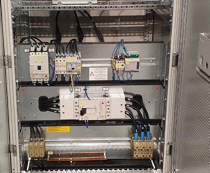
PRODUCT LINE | DC CURRENT
DC/DC CONVERTER DC1
TYPE DC1-12 DC1-24 DC1-48 DC1-110
NOMINAL VOLTAGE* 12 24 48 110
DC/DC MODULE 10÷60A
CURRENT RANGE
MAX POWER 720W 1440W 2880W 6600W
RIPPLE NOISE(RMS) ≤ 0.3% Vn
RANGE REGOL.Vout +/- 5%
OUTPUT
STABILITY +/- 1%
ADJ. FOLLOWING THE CHANGE
+/- 1%
Vinp.
ADJ. FOLLOWING THE CHANGE
+/- 1%
lLoad
START-UP time 2 sec.
CONFIG. PARALL. OF
POSSIBLE WITH BLOCK DIODE
REDUNDANCY
VOLTAGE RANGE */** 18 ÷ 75 116 ÷ 170
EFFICIENCY (Typ.) ≥ 90 %
INPUT
CURR.CONSUMPTION (NO LOAD) ~ 0.2 Amp
INRUSH CURRENT (Typ.) ~ 80Amp
2In x 5mS
OVERLOAD
Shut down for 250mS - restart aut.
CURRENT TYPE CONSTANT
PROTECTION
DC/DC MODULE - REAR OVP + 10% Vn
UVP - 50% Vn
OVERTEMP. Shut down. Restart aut.
ALARMS DC/DC OK SPDT CONTACT (5Amp/230VAC)
MAIN FEATURES WORKING TEMP. -10 ……+40°C
•• Static converter ENVIRONMENT WORKING HUMIDITY 20 ……90% (NO COND.)
•• Configuration: STEP-DOWN
•• Control type: PWM HF. STORAGE TEMP. -20 ……+50°C
•• Isulation I/O: NO MARKING CE
•• Negative pole through PROTECTION DEGREE IEC 60529
•• Extractable 5U rack-format AC/DC module for quick STANDARDS
EMC EN 61000-6-2 EN 61000-6-4
and easy assistance thanks to polarized extractable
connectors STATIC CONVERTER EN 60146
Iout= 5÷20Amp NATURAL
APPLICATION FIELDS VENTILATION
Iout= 21÷60Amp FORCED
These converters can be used to power utilities in DC with
PRODUCT LINE
DIMENSIONS ( W x D x H) mm- with handle and rear clamps 5U rack type 482 x 485 X 221
constant voltage, when it has a variable trend source such as
DIMENSIONS ( W x D x H) mm- without handle and rear clamps 5U rack type 482 x 425 X 221
the batteries that require charging curves to voltage values
not always acceptable by the loads. PROTECTION DEGREE IP20
PAINT FRONT PANNEL - INDICATIVE WEIGHT RAL 7035 - 15Kg
AC CURRENT
LCD CARD (Vout & Iout)
OPTIONS
IN OUT BLOCK DIODE
VDC AUX1 OK
VDC AUX 2 OK
DRIVING IGBT OK
LEDS ALARMS ON CONTROL
CARD UNDER VOLTAGE IN PROGRESS
OVER VOLTAGE IN PROGRESS
OVERTEMPERATURE IN PROGRESS
COMMANDS MANUAL SELECTOR FOR ON/OFF CONVERTER
STATUS LED GREEN LED FOR CONVERTER IN USE
*Others on request.
**With converter operating in regulation.
14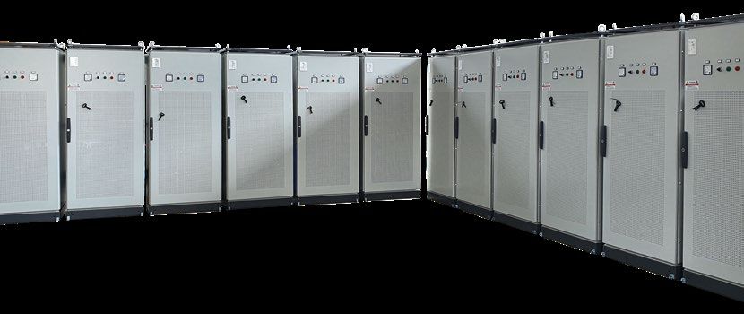
PRODUCT LINE | AC CURRENT

                                  EMERGENCY POWER SYSTEM 400-3000VA SMI SERIES

                                                                                                      MAIN FEATURES
                                                                                                      •• High frequency PWM Inverter
                                                                                                      •• Single-phase input
                                                                                                      •• Single-phase sinusoidal output
                                                                                                      •• Isolation transformer in the inverter output
                                                                                                      •• Efficiency DC/AC high
                                                                                                      •• Microprocessor control with 32 bit
                                                                                                      •• Leds for clear information about the status of the E.P.S.
                                                                                                      •• Short trasfer time, less than 10 msec (short break)
                                                                                                      •• Rescue operation (output always present)
                                                                                                      •• Internal battery - Nominal voltage 24Vdc (S.E.L.V.)
                                                                                                      •• Suitable for any type of safety utilization
                                                                                                      •• Specific for led lights, suitable for any other type of load (small pumps, motors power
                                                                                                         factor corrected lamps or lights, small refrigerators)
                                                                                                      •• Compact and small dimensions
                                                                                                      •• Easy wall installation
                                                                                                      •• OPTIONS
                                                                                                      •• Emergency Power Off (E.P.O.) for Inverter shutdown immediate
                                                                                                      •• Possibility of increasing autonomy with adeguate charger
                                                                                                      •• Auto Off to load  99%; on battery working > 90%
                                                                                                                                         6 - 10 for full autonomy
INDUSTRIAL UPS PRODUCTIONS        BATTERIES         RECHARGE TIME
                                                    NOISE (dbA at 1 meter)                                                                         < 40
WITH OUTPUT FOR DC AND AC LOADS                     TEMPERATURE                                                                                da 0 a 40 °C
                                                    RELATIVE HUMIDITY AT 35° C                                                             90% non-condesing

SPECIAL
                                  GENERAL
                                  NOTES             UPS DIMENSIONS (L X P X H) mm                                                            315 x 255 x 550
                                                    WEIGHT (KG) without batteries                                                               In progress

PRODUCTS
                                                    COMPLIANCE                                                 Safety EN 62040-1-2, EMC EN 62040-2, CSS EN 50171 (battery on request)
                                                    ELECTRONIC                                                                    Overload - short circuit - battery low
                                  PROTECTION        ELECTRIC                                                                Input and output fuses and battery fuse (internal)
                                                    MECHANICAL                                                                                     IP20
                                                    OPTICAL                                                             Functional E.P.S. - Overload - battery low - general alarm
                                  ALARMS
                                                    ACOUSTIC                                                                 Line fails - battery low - overload - test battery

                                  ACCESSORIES

                                  CODE        DESCRIPTION
                                  7050        Communication port RS485

                                  7011E       Emergency Power Off (E.P.O.) for Inverter shutdown immediate

                                  7013E       Dry general alarm

                                  7051E       Emergency operation

                                                                                                                                                                                                   17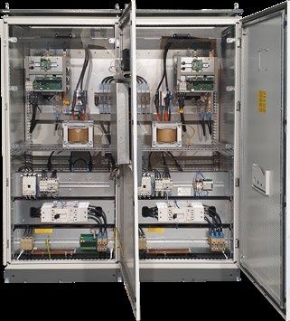
PRODUCT LINE | AC CURRENT PRODUCT LINE | AC CURRENT
EMERGENCY POWER SUPPLY 1-10KVA SMED SERIES EMERGENCY POWER SUPPLY 1-10KVA SMED SERIES
POWER TYPE CODE AUT. (min.) OVERALL (LxPxH) (mm) BATTERIES WEIGHT (Kg)
MAIN FEATURES SMED10-10 4M1000-10 10’ 320 x 650 x 650 n.4 12V-9Ah 68
1000VA
•• High frequency PWM Inverter 900W
SMED10-30 4M1000-30 30’ 320 x 650 x 650 n.12 12V-7Ah 82
•• Single phase input SMED10-60 4M1000-60 60’ 320 x 650 x 650 n.20 12V-7Ah 108
•• Single phase sinewave output
SMED15-10 4M1500-10 10’ 320 x 650 x 650 n.8 12V-7Ah 74
•• Isolation transformer on the inverter output 1500VA
•• High DC/AC efficiency 1350W
SMED15-30 4M1500-30 30’ 320 x 650 x 650 n.20 12V-7Ah 108
•• Microprocessor management with Auto-Diagnostics SMED15-60 4M1500-60 60’ 320 x 650 x 650 n.24 12V-9Ah 122
•• LCD display for more clear information about the status
SMED20-10 4M2000-10 10’ 320 x 650 x 650 n.8 12V-9Ah 91
•• Automatic on/off weekly timer 2000VA
•• Automatic and manual battery test (emergency version) 1800W
SMED20-30 4M2000-30 30’ 320 x 650 x 650 n.20 12V-9Ah 128
•• Transfer time less than 200 msec SMED20-60 4M2000-60 60’ 320 x 650 x 650 n.32 12V-9Ah 157
•• Rescue or emergency operation (SA/SE) selectable SMED30-10 4M3000-10 10’ 320 x 650 x 650 n.12 12V-9Ah 103
•• Possibility of connection forany user normally destined for security 3000VA
2700W
SMED30-30 4M3000-30 30’ 320 x 650 x 650 n.24 12V-9Ah 141
OPTIONAL
SMED30-60 4M3000-60 60’ 420 x 850 x 1050 n.48 12V-9Ah 224
•• Contact interface
SMED40-10 4M4000-10 10’ 320 x 650 x 650 n.16 12V-9Ah 118
•• Communication interface (RS-232) and management software
4000VA
•• USB interface 3600W
SMED40-30 4M4000-30 30’ 320 x 650 x 650 n.32 12V-9Ah 170
•• Kit Ethernet SNMP adapter and related software SMED40-60 4M4000-60 60’ 420 x 850 x 1050 n.60 12V-9Ah 268
•• Remote synoptic LCD remote
SMED50-10 4M5000-10 10’ 320 x 650 x 650 n.20 12V-9Ah 138
•• Relay alerts and status communication card 5000VA
•• Manual by-pass 4500W
SMED50-30 4M5000-30 30’ 320 x 650 x 650 n.40 12V-9Ah 201
•• Emergency Power Off contact (E.P.O.) for immediate stop SMED50-60 4M5000-60 60’ 420 x 850 x 1050 n.80 12V-9Ah 318
•• Possible starting even without input power
SMED60-10 4M6000-10 10’ 320 x 650 x 650 n.20 12V-9Ah 151
•• Double out possibility SA+SE 6000VA
•• DC output 5400W
SMED60-30 4M6000-30 30’ 320 x 650 x 650 n.60 12V-9Ah 270
•• Batteries Long Life 10 years expected (according to EN50171 SMED60-60 4M6000-60 60’ 420 x 850 x 1050 n.120 12V-7Ah 403
SMED80-10 4M8000-10 10’ 420 x 850 x 670 n.40 12V-7Ah 187
8000VA SMED80-30 4M8000-30 30’ 420 x 850 x 1050 n.80 12V-9Ah 328
7200W
SMED TYPE 10 15 20 30 40 50 60 80 100 420 x 850 x 670 + 95 +
SMED80-60 4M8000-60 60’ n.40 12V-26Ah
NOMINAL POWER (KVA) 1 1,5 2 3 4 5 6 8 10 540 x 715 x 1250 415
POWER
ACTIVE POWER (KW) 0,9 1,35 1,8 2,7 3,6 4,5 5,4 7,2 9 SMED100-10 4M10000-10 10’ 420 x 850 x 670 n.40 12V-9Ah 214
VOLTAGE 230Vac +/-20% SMED100-30 4M10000-30 30’ 420 x 850 x 1050 n.80 12V-9Ah 343
INPUT 10000VA
FREQUENCY 50Hz +/-5% 9000W
420 x 850 x 670 + 105 +
SMED100-60 4M10000-60 60’ n.40 12V-42Ah
Present mains: mains voltage 540 x 715 x 1250 620
VOLTAGE
On batteries: 230 Vac +/- 0,5%
Present mains: synchronized to mains
FREQUENCY
On batteries: 50Hz +/- 0,005%
OUTPUT ACCESSORIES
OVERLOAD 110% for 60 sec. - 130% for 10 sec. - short circuit management
CODE DESCRIPTION
WAVEFORM Sine wave
VOLTAGE DISTORTION (THD) < 3% (linear load) 7001 Remote synoptic with 15mt cable
EFFICIENCY at full load Present mains > 98%; on batteries on> 91% 7002-IN Relay alarm communication card inside the E.P.S. (when ordering)
BACK-UP TIME See the detailed tables 7002 External relay alarm communication board (requires the addition of accessory 7012)
BATTERIES
RECHARGE TIME 8h 7003 External SNMP Ethernet interface (requires the addition of the 7007R accessory)
NOISE (dbA at 1 meter) < 40 7006-70 Manual bypass for SMED 10-50
TEMPERATURE from 0 to 40 °C
7006-140 Manual bypass for SMED 60-100
RELATIVE HUMIDITY AT 35° C To 90% non-condensing
7007R RS232 communication interface
GENERAL NOTES UPS DIMENSIONS (L X P X H) mm 320 x 650 x 650 / 420 x 850 x 670 / 420 x 850 x 1050 (See the detailed tables)
7011M Contact for emergency button (E.P.O.) for immediate inverter stop
PACKING DIMENSIONS (L X P X H) mm 420 x 740 x 850 / 530 x 920 x 760 / 530 x 920 x 1140 (See the detailed tables)
7012 Contacts interface
WEIGHT (KG) without batteries See the detailed tables
COMPLIANCE Safety EN 62040-1-2, EMC EN 62040-2, CSS EN 50171 (batteries excluded)
7018 USB interface
ELECTRONIC Overload - short circuit - battery low GSC026040S Box with 2x20 batteries 12V-26Ah and safety breaker Overall 540 x 715 x 1250 mm 415 Kg
PROTECTION ELECTRIC Input and batteries fuses – circuit breaker output GSC042040S Box with 2x20 batteries 12V-42h and safety breaker Overall 540 x 715 x 1250 mm 620 Kg
MECHANICAL IP20 7030 Battery Start button
OPTICAL Functional emergency power system status - overload - low battery 70SS-30D Possibility of double output SA + SE for SMED 10-30
ALARMS
SOUNDS ALERT Mains fail - low batteries - overload - test battery 70SS-100D Possibility of double output SA + SE for SMED 40-100
18 19PRODUCT LINE | AC CURRENT
UNINTERRUPTIBLE POWER SUPPLY – UPS MTS MM/TM 3÷14KVA SERIES
MAIN FEATURES
•• Tecnology On-Line double conversion with transformer - VFI-SS-111
•• Single or trhee phase input
•• Single phase output
•• High AC/DC efficiency
•• PFC circuit on the intput
•• Microprocessor control with Self-Diagnostics
•• Automatic by-pass standard
•• LCD display for more clear information about UPS status
•• Turn on and turn off by weekly timer
•• Communication port RS232
OPTIONS
•• SNMP adapter and software
1996-2021 •• Communication board and relay alarms (AS400)
•• Possibility of starting also from batteries
we work to give
•• Available as voltage and/or frequency convert
energy MTS 30/40/55/70 available
in rack version
SNMP Ext.
MTS SERIES 30 40 55 70 100 140
POWER (KVA) 3 4 5,5 7 10 14
POWER
POWER (KW) 2,1 3 4 5 7,5 10
SINGLE PHASE 230 Vac +10/-20%
INPUT FREQUENCY 50 Hz +/- 5%
POWER FACTOR > 0,98
RATED VOLTAGE 230 Vac +/- 0,5%
FREQUENCY Line working: synchronized to line - Battery working: 50Hz +/- 0,005%
OVERLOAD 110% for 60 sec. - 130% for 10 sec. – short circuit management
OUTPUT
WAVEFORM Pure wave
VOLTAGE DISTORSION THD < 3% (with linear load)
EFFICIENCY at full load 91% - on ECO Mode >98%
TYPE 12 V - 7 Ah 12 V - 12 Ah
NUMBER 10 12 16 20
BATTERIES
TYPICAL AUTONOMY 10’ 13’ 10’
RECHARGE TIME 8h
AUDIBLE NOISE (db at 1 mt.) 40 to 60
OPERATING TEMPERATURE 0 to 40° C
RELATIVE HUMIDITY AT 35°C < 90% non-condensing
GENERAL NOTES UPS DIMENSIONS (LxPxH) mm 320x650x650 420x850x670
UPS RACK DIMENSIONS (LxPxH) mm 630x570x710 -
WEIGHT (KG) 90 95 113 132 180 195
COMPLIANCE Safety EN 62040-1-2 / EMC EN 62040-2 / EN 62040-3
ELECTRONIC Overload / short circuit / low battery
PROTECTION ELECTRIC Input and battery fuses - automatic switch on output
MECHANICAL IP20
OPTICAL Function UPS status - overload - low battery
ALARMS
ACOUSTIC Line failure - low battery - overload - battery test - inverter off
21PRODUCT LINE | AC CURRENT PRODUCT LINE | AC CURRENT
UNINTERRUPTIBLE POWER SUPPLY – UPS M 600÷1.5KVA SERIES UNINTERRUPTIBLE POWER SUPPLY – UPS MKK 1÷10KVA SERIES
MAIN FEATURES MAIN FEATURES MKK MAIN FEATURES MKK
•• Tecnology line interactive –VI-Sy-222 1000÷3000 6000÷10000
•• AVR Stabi •• Microprocessor control with Self- •• Technology "on-line" double conversion
•• Microprocessor management Diagnostic transformer less VFI-SS-111
•• Response time < 4mS •• Automatic by-pass as standard •• Input and output sinle phase (pure sinewave
•• High efficiency
•• Self-Diagnostic •• LCD display •• PFC circuit input
•• Self-learnig •• Batt. level •• Microprocessor control with Self-Diagnostic
•• LCD display for more clear information about UPS status •• Load level •• Automatic and manual by-pass as standard
•• RS232 and/or USB communication port •• RS232 and USB interface •• LCD display
•• Control software •• Batt. level
•• Control and management software
•• Contact for emergency button (EPO) on •• Load level
•• Telephone line and modem protection with RJ11 •• RS232 and USB interface
•• Computer network protection with RJ45 the PLUS series •• Control software
OPTIONS
OPTIONS
•• SNMP adapter and related software •• SNMP adapter and related software
•• Communication board relay alarm •• Communication board relay alarm (AS400)
(AS400) •• Parallel mode
MKK- MKK- MKK-
M SERIES M600 M800 M1000 M1500 SAT-KE SERIES MKK MKK MKK MKK
PLUS PLUS PLUS
NOMINAL POWER (VA) 600 800 1000 1500 POWER (VA) 1000 2000 3000 6000 10000
POWER
ACTIVE POWER (W) 360 480 600 900 POWER (W) 800 900 1600 1800 2400 2700 4200 7000
POWER SINGLE PHASE VOLTAGE 200/295 Vac at full load 220/230Vac +20/-25%
VOLTAGE 230 Vac ±25% INPUT FREQUENCY 40-55 a 50Hz / 55-65Hz (autosensing) 50/60Hz +/- 5%
FREQUENCY 50 o 60 Hz ± 10% (autosensing) POWER FACTOR > 0,98
SINGLE PHASE VOLTAGE 208/220/230/240 (selectable) +/-2% 230 +/- 3%
VOLTAGE Line working: 230 Vac ± 9% (AVR) - Battery working: 230 Vac ± 10%
50/60Hz
OUTPUT FREQUENCY (HZ) on battery working 50/60 +/-0,2%
FREQUENCY Line working: synchronized to line - Battery working: 50Hz o 60Hz ± 1Hz (sel. auto) +/- 5%
OUTPUT
OUTPUT FREQUENCY (HZ) with power on Synchronized to line
WAVEFORM Pure wave
108%±5%< load≤150%±5% >30s loss of the load connected and alarm 110% for 10 min;
N° OF OUTPUT SOCKET 4 6 OVERLOAD
OUTPUT 150%±5%< load< 200%±5%> 300ms loss of the load connected and alarm 130% for 1 min
TYPE 12V - 7Ah 12V - 9Ah 12V - 7Ah 12V - 9Ah WAVEFORM Pure sinewave
NUMBER 1 1 2 2 TOTAL HARMONIC DISTORSION (THD) < 3% (linear load)
BATTERIES
TYPICAL AUTONOMY from 10’ - to 20’ EFFICIENCY at full load With power on >90% (PLUS version: >91%) on Eco mode >98%
4+4 IEC 10A
RECHARGE TIME 6 - 8h N. OF OUTPUT SOCKET 3 IEC 10A 1+2 IEC 10A 4 IEC 10A 4+4 IEC 10A 4 IEC 10A Clamps
+1 IEC 16A
AUDIBLE NOISE (db at 1 mt.) < 30 BYPASS AUTOMATIC Switching without disconnect (100%) from UPS to BYPASS and return
OPERATING TEMPERATURE from 0 to 40 °C TYPE 12V-9Ah 12V-7Ah 12V-9Ah 12V-7Ah 12V-9Ah 12V-9Ah 12 V - 7,2Ah 12V - 9Ah
RELATIVE HUMIDITY AT 35° C 90% non-condensing NUMBER 2 3 4 6 20
BATTERIES
GENERAL NOTES UPS DIMENSIONS (LxPxH) mm 101 x 298 x 142 149 x 338 x 162 158 x 380 x 198 AUTONOMY From 8 to 15 minutes, load-dependent
RECHARGE TIME 6 - 8h
UPS RACK DIMENSIONS (LxPxH) mm 140 x 350 x 210 195 x 405 x 235 220 x 445 x 285
AUDIBLE NOISE (dba at 1 m.) < 55dBA < 45dBA
WEIGHT (Kg) without batteries 4,25 4,9 7,8 11,1
OPERATING TEMPERATURE 0 to 40 °C
COMPLIANCE Security EN 62040-1-2 / EMC EN 62040-2 / EN 62040-3
RELATIVE HUMIDITY AT 35° C < 90% non-condensing
ELECTRONIC Overload / short circuit / low battery UPS TOWER DIMENSIONS (WxDxH) mm 144x361x215 144x409x215 191x428x337 191x466x337 191x428x337 191x466x337 270x570x720
ELECTRIC Input and battery fuses UPS PACKING DIMENSIONS (WxDxH) mm 215x455x300 215x503x300 310x535x445 310x573x445 310x535x445 310x573x445 370x670x940
PROTECTION GENERAL
MECHANICAL IP20 NOTES 440x380x86,5 440x520x131 440x520x131
UPS RACK PACKING DIMENSIONS (WxDxH) mm - - - -
(2U) (3U) (3U)
MODEM PROTECTION yes UPS RACK (WxDxH) mm 610x515x180 - 610x660x215 - 610x660x215 - -
OPTICAL Mains ok / battery mode / overload UPS TOWER WEIGHT (Kg) 11 13 21 24 26 - 95 98
ALARMS
ACOUSTIC Line failure - low battery - overload UPS RACK WEIGHT (Kg) 11 - 21 - 26 -
COMPLIANCE Safety EN 62040-1-2, EMC EN 62040-2, EN 62040-3
22 23PRODUCT LINE | AC CURRENT PRODUCT LINE | AC CURRENT
DC/AC INVERTER MTS - INV SERIES STATIC SWITCH MTS - COM SERIES
The new MTS-INV series inverters are the result of careful studies to develop a high
efficiency and high performance product, all made in a compact box. These DC / AC
conversion systems take energy from direct voltage sources such as rectifiers and The Statich Switch of the MTS-COM series they allow the switching of the
buffer batteries, guaranteeing power and continuity even when the AC power sources users connected to it, from a Priority input line (selectable), to the Reserve
are no longer available. input line, in automatic and / or Manual mode.
Thanks to the numerous versions available as input voltage and power, the uses
Switching takes place in time 0 (less than 1 m sec.) with synchronous inputs
can be different and therefore ideal for supplying quality power and continuity to the
equipment, for example ruter etc. or in some electrical transformer substations for in frequency, while in the case of asynchronous inputs, switching takes place
the 110Vdc versions. Optional interfaces allow remote monitoring even if installed in with a delay of only 7/8 m sec.
unmanned environments.
MAIN FEATURES
MAIN FEATURES
•• Inverter MOSFET with low loss at high frequency with high efficiency •• Two input (N in common, fix in and out)
•• Wide DC input range •• A first line selectable
•• Output 230Vac, single phase, pure sinewave
•• One output
•• Isolating transformer on the inverter output
•• Limit inrush current at power start •• Microprocessor control
•• DSP microprocessor for inverter control and management user interfaces •• Easy to use
•• Display and leds for greater information on the status of the inverter •• Leds to inform on the status
•• Self-diagnosis of faults
•• Neutral cable passing between in and out
OPTIONS
•• Pulse input (TTL)
•• E.P.O. (Emergency Power Off)
•• Alarms on dry contact
•• Internal static bypass switch
•• Communication interface RS232 and software for monitoring and management TYPE MTS - COM 5 MTS - COM 10 MTS - COM 20
•• SNMP adapter with software 5 10 20
POWER NOMINAL POWER 5KVA 10KVA 20KVA
22A 44A 88A
VOLTAGE 2 x 230 Vac +/- 15% (neutral in common)
6000** INPUT
MTS - INV TYPE 1000 1500 2000** 3000** 4000** 5000**
FREQUENCY 50Hz
POWER POWER (W) 1000 1500 2000 3000 4000 5000 6000
VOLTAGE The same of input
INPUT DC INPUT VOLTAGE 24 / 48 / 60 / 110 / 220 / 250 Vdc (ask on the order)
VOLTAGE 230 Vac +/-3% FREQUENCY 50Hz
FREQUENCY 50Hz +/- 0,05% OVERLOAD 110% for 60 sec. - 130% for 10 sec.
OUTPUT
OVERLOAD 110% per 60sec - 130% per 10sec - short circuit management WAVEFORM Sinewave
OUTPUT WAVEFORM sinewave
EFFICIENCY 99%
VOLTAGE DISTORTION (THD) < 2% with full linear load
CONNECTIONS clamps
EFFICIENCY AT FULL LOAD 92%
CONNECTIONS clamps NOISE (dbA at 1 meter) < 40
NOISE (dbA at 1meter) < 40 OPERATING TEMPERATURE 0 to 40° C
OPERATING TEMPERATURE da 0 a 40 °C
HUMIDITY < 90% non-condensing
RELATIVE HUMIDITY AT 35° C fino al 90% non-condensing
RACK DIMENSIONS (WxDxH) mm 483 x 334 x 90 (2U)
483 x 475 x
GENERAL DIMENSIONS (W x D x H) mm* 483 x 355 x 95 (2U) 483 x 475 x 222 (5U)
NOTES
133 (3U) GENERAL NOTES PACKING RACK DIMENSIONS (WxDxH) mm 540 x 410 x 165
630 x 570 x
PACKING DIMENSIONS (L x P x H) mm 630 x 570 x 220 650 x 570 x 440 (5U) SWITCH BOX DIMENSIONS (WxDxH) mm 325 x 180 x 425
270
WEIGHT (Kg) 18 20 24 27 35 37 SWITCH BOX ACKING RACK DIMENSIONS (WxDxH) mm 340 x 200 x 480
COMPLIANCE Safety EN 62040-1, EMC EN 62040-2, efficiency EN 62040-3 WEIGHT (kg) 10 11
ELECTRONIC Overload - short circuit - min/max input voltage - output low voltage
COMPLIANCE safety EN 62310 - 1, EMC EN 62340-2
PROTECTIONS ELECTRIC input fuse
ELECTRIC Magnetic breakers or fuse
MECHANICAL IP20
PROTECTIONS
OPTICAL Status of the inverter - overload - alarms MECHANICAL IP20
SIGNALLING
ACOUSTIC Overload - short circuit - min/max input voltage - output low voltage SIGNALLING OPTICAL INPUT LINE - OUTPUT LINE
* With options the dimensions can be different. Possibility of others power size, with custom solutions.
* * Models with 24 VDC power supply are excluded.
24 25PRODUCT LINE | ACCESSORIES
BATTERY MONITORING UNIT
The growing demand for systems that guarantee ever greater continuity of
service, powered by direct current, consequently leads to the development
of equipment monitoring systems in order to make the system even more
reliable, avoiding unexpected and unexpected failures.The most vulnerable
point of the system has been identified in the dc power source, formed by
batteries, and therefore a device has been developed capable of controlling
the operating status of both the entire bench and each individual battery.
The BM1 device is equipped with LED indicator lights to immediately identify
the battery with irregular operation and free voltage contacts prepared for
remote alarms. Made in a practical 2-module DIN rail case, it can be easily
Single module BM1 Detail of the front panel installed above the accumulator itself or in a common electrical switchboard.
The BM1 devices can be connected to optional interface modules to be able
to send the operating status of the batteries to which it is connected remotely
and / or on a computer network.
In this way it is possible to program maintenance operations well in advance,
avoiding a sudden failure and compromising the continuity of the service.
The device is suitable for 12 V batteries and having the same electrical
characteristics.
TECHNICAL DATASHEET
Optional communication device for remotely reporting battery INPUT NOMINAL VOLTAGE 12 VDC
status (no electrical measurements).
INPUT RANGE VOLTAGE 8 ÷ 16 VDC
CURRENT CONSUMPTION 19 ÷ 50 mA
POWER SUPPLY From battery
TYPICAL OF CONNECTION OPERATING TEMPERATURE 0 ÷ 40 °C
WITH POSSIBLE REMOTE ALARM REPORT
RELATIVE HUMIDITY < 90 % non-condensing
PROTECTION DEGREE IP20
PRODUCT LINE
ELECTRICAL PROTECTIONS Autoreset fuses
REVERSE POLARITY PROTECTION Yes
ACCESSORIES
12 VDC
Vmax*: SET = 14.5 RESET = 13.5 VDC
STATUS ALARMS BUS ALARMS SETUP
Vmin: SET = 9.5 RESET = 12.5 VDC
Vric/rech** SET = 11.5 RESET = 13.0 VDC
Max. voltage: 125 VAC 30 VDC
INTERNAL RELAY DATASHEET
Max. current: 1 Amp
TYPE device BM1: 36*58*90mm
Easy to install with extremely small dimensions, it also allows the DIMENSIONS (WxDxH)
2M standard DIN 43880
less experienced person to immediately establish the status of the
batteries by identifying the faulty ones. * The alarm status is activated after 2 minutes from which the battery is within
the indicated range.
** If the battery remains in this condition for 8 hours the alarm is activated.
26 27PRODUCT LINE | ACCESSORIES
CONSULTING
COMMISSIONING PROCEDURE
REMOTE ALARM DEVICE Analysis during an inspection, followed by a project that takes into account
The commissioning procedure ensures proper operation of the system. If you
your requests. This includes a diagnosis and inspection of the batteries. Let our
have chosen an MTS Elettronica system solution, we will guide you all along
team of technicians advise you. They have extensive experience in the field of
the way from the moment you place your order. From design and production,
batteries and the equipment connected to them.
through testing and delivery, to installation and on-time and precise commis-
DIN RAIL VERSION sioning. QUALITY AT THE FOREFRONT
TABLE VERSION Cod. RA-09-DIN PREPARING FOR COMMISSIONING MTS Elettronica uses specific batteries for each system, with a 12-mon-
Cod. RA-09
•• The equipment must be positioned and the electrical installation th warranty. We offer you complete installation and replacement of your old
completed battery system, including professional removal and disposal. This spares you
•• Plan the technical intervention with MTS Elettronica at least 2 weeks unplanned investments and ensures the highest possible performance from
in advance on site needs your system.
WHAT DOES COMMISSIONING INVOLVE? AFTER-SALES SERVICE
DESCRIPTION RA - 09 RA - 09 - DIN MTS Elettronica offers various types of service able to satisfy additional reque-
Our technicians carry out a series of checks to ensure correct installation and
VAC 230 VAC 12 VAC¹ 230 VAC² operation of the system in accordance with specifications: sts both in technical and economic terms. Our contracts offer the most effecti-
12 VDC¹ •• Visual inspection of the installation site ve protection for your installations. In addition, unnecessary costs from un-
SUPPLY VOLTAGE 24 VDC¹ •• Visual inspection of equipment and batteries to identify damage planned failures and downtime are avoided. MTS Elettronica service contracts
VDC include prompt and professional telephone support, a preliminary inspection
48 VDC² •• Check of conformity of the installation conditions
110 VDC² •• Equipment inspection and response time tailored to your requirements, as well as material costs and
INPUTS NR. 4 4 •• Battery array wiring inspection working hours in the event of malfunctions depending on your critical applica-
INPUTS TYPE N.O and N.C. N.O and N.C. •• Check of compliance with current safety regulations tions and investment plan.
DELAY ON ACTIVATION (Adj) 0 ÷ 300 sec. 0 ÷ 300 sec. •• Inspection of the upstream and downstream protection devices of FOCUS
DELAY AT OFF 5 sec. - fix 5 sec. - fix the systems and battery array
LED test button and buzzer silencing LED test button e Acknowledgeable audible alarm •• Check of the VAC supply line •• Service contracts for installed rectifiers and UPSs
SETUP DEVICE
Configuration dip-switch Configuration dip-switch •• System start-up with checkup of all main electrical parameters •• Joint planning of intervention dates
OUTPUT ALARMS LED + buzzer + cumulative relay LED + buzzer + cumulative relay •• Tests with real load applied to the system •• Contracts even at the end of the warranty period
CUMULATIVE RELAY CONFIGURABLE IN POSIT./NEGAT LOGIC. Yes Yes •• Simulation of power failure and checkup of the battery array •• Service contracts tailored to individual needs
I/O CONNECTIONS TYPE Clamps PCB Clamps PCB •• Tests on systems for interfacing and communicating with the outside SOLUTIONS
BOX DIMENSIONS 168*138*48 (p )mm DIN 4M world
PROTECTION DEGREE IP30 IP20 - box / IP50 - front CHECK OF INSTALLATION BASE MIDDLE PROFESSIONAL
BOX TYPE Metallic Plastic / Self-extinguishing
•• Inspection of the entire equipment and control of cabling
CONTACT N.O-C-NC / CONTACT N.O-C-NC /
INTERNAL RELAY DATASHEET
1 Amp - 24VDC / 0.5 Amp - 110VAC 1 Amp - 24VDC / 0.5 Amp - 110VAC
•• Inspection of battery connections
•• Compliance with local security standards and regulations Years 1 year 3 years 5 years
WEIGHT 450g 120g
•• Dimensioning of protective equipment
SUPPLIED AUXILIARY FEEDER OF SERIES Yes NO
•• Check of neutral line and star centre Periodic checks
¹ Accepts direct power supply.
Annual
1 1 1
² Requires external adapter (optional) INSTRUMENTAL SURVEYS AND CHECKS
•• Technical checks carried out with certified instruments
This device can manage up to four inputs with a range between 0 ÷ 300 sec. giving the device a with the general fault function are also made Corrective actions
•• Operation test of the entire system
signals coming from voltage-free contacts (relays) feature of unparalleled flexibility in use. On the front available on the terminal board so as to signal
associated with as many LED indications. panel there are six LEDs and a button, namely: the status also to other external devices. The Why choose commissioning by MTS Elettronica:
•• Certainty of correct operation of the equipment ELECTRONIC spare
The selection of the type of input contact, (it is •• n° 4 red color for input channels status connections to the four input channels are available parts
possible to manage types of contact both Normally •• n° 1 green color for regular operation status through a modular terminal block and / or via an •• Technical training of its staff
Open and Normally Closed) occurs through internal •• n° 1 red color for general failure status RJ45 connector for a Cat.5 twisted cable (only in •• Longer service life of the system
dip-switches available in single form for each •• n° 1 pbutton with acoustic alarm silencing the RA-09 version). The RA-09 device requires a 12 •• Ad-hoc parameterizations for each type of use Software updates
channel, moreover, each input is provided with the function and LED test VDC power supply guaranteed by an external 230 •• Specific technical advice
excitation delay function adjustable by trimmer, in The contacts (COM-NO-NC) of a relay associated VAC input power supply unit supplied as standard. •• Possibility of warranty extension
Spare parts priority
COMMITMENT TO BATTERIES
TECHNICAL DATA MM TM TT TTmax Priority technical
Replacing batteries is a matter of security and is a crucial investment to pro-
MANUAL BYPASS INPUT tect a system. The battery is a main component of the system. It can only be assistance
ELECTRICAL SETUP Ph+N 3Ph+N 3Ph+N 3Ph+N replaced by the manufacturer. Thanks to MTS Elettronica's battery replace-
ment programme, you can be sure that only batteries that have been tested ADVANTAGES
NOMINAL VOLTAGE 230 VAC 400 VAC 400 VAC 400 VAC
and approved for your system will be used.
FREQUENCY 50 – 60Hz •• Guaranteed response times
MTS Elettronica offers durable and reliable batteries at the best price. Building •• Optimised working time
MAXIMUM CURRENT 63 Amp 100 Amp 100 Amp 125 ÷ 400 on the experience gained from the numerous systems installed and through •• Reduced downtime costs and cost-optimized support
OUTPUT collaborations with leading companies in the sector, we ensure your security •• Efficient on-site support by qualified personnel
NOMINAL VOLTAGE 230 VAC 230 VAC 400 VAC 400 VAC
and that of your investments in technology. •• System historical data recording
OUR SERVICES •• Technical service reports
SETUP
•• Guaranteed exclusive use of original spare parts
OPERATING TEMPERATURE 0°c ÷ 40°c BATTERY REPLACEMENT •• Use of certified measuring instruments
RELATIVE HUMIDITY 0 ÷ 90% non-condensing
This includes replacing the batteries on site and putting them back into servi-
DIMENSIONS (WxDxH) mm 395*125*395 ** ce. This service ensures compliance with the relevant technical and environ-
WEIGHT (kg) 4 4.5 5.5 ** mental specifications.
MTS - BYPASS allows to exclude UPS in case of maintenance or
malfunction, without causing power loss. Easy to install, it comes PROTECTION DEGREE IP20
in handy wall panel. **= To be defined based on the current required.
28You can also read


