Charger Police STICK WITH THE SPECIALISTS
←
→
Page content transcription
If your browser does not render page correctly, please read the page content below
2018 Charger Police
                                   STICK WITH THE SPECIALISTS®

                                                                                                                      2018
                                                                                                               OWNER’S MANUAL
                                                                                                                                Charger Police
18LDPOL-126-AA
©2017 FCA US LLC. All Rights Reserved.                                   First Edition                            SUPPLEMENT
Dodge is a registered trademark of FCA US LLC.                   Printed in the U.S.A.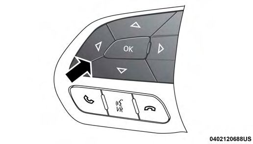
VEHICLES SOLD IN CANADA                                       This manual illustrates and describes the operation of
With respect to any Vehicles Sold in Canada, the name         features and equipment that are either standard or op-     INSTALLATION OF RADIO TRANSMITTING                              The antenna cable should be as short as practical and
FCA US LLC shall be deemed to be deleted and the name         tional on this vehicle. This manual may also include a     EQUIPMENT                                                       routed away from the vehicle wiring when possible. Use
FCA Canada Inc. used in substitution therefore.               description of features and equipment that are no longer   Special design considerations are incorporated into this        only fully shielded coaxial cable.
                                                              available or were not ordered on this vehicle. Please      vehicle’s electronic system to provide immunity to radio
DRIVING AND ALCOHOL                                                                                                                                                                      Carefully match the antenna and cable to the radio to
                                                              disregard any features and equipment described in this     frequency signals. Mobile two-way radios and telephone
Drunken driving is one of the most frequent causes of                                                                                                                                    ensure a low Standing Wave Ratio (SWR).
                                                              manual that are not on this vehicle.                       equipment must be installed properly by trained person-
accidents.
                                                                                                                         nel. The following must be observed during installation.        Mobile radio equipment with output power greater than
Your driving ability can be seriously impaired with blood     FCA US LLC reserves the right to make changes in design                                                                    normal may require special precautions.
alcohol levels far below the legal minimum. If you are        and specifications, and/or make additions to or improve-   The positive power connection should be made directly
drinking, don’t drive. Ride with a designated non-            ments to its products without imposing any obligation      to the battery and fused as close to the battery as possible.   All installations should be checked for possible interfer-
drinking driver, call a cab, a friend, or use public trans-   upon itself to install them on products previously manu-   The negative power connection should be made to body            ence between the communications equipment and the
portation.                                                    factured.                                                  sheet metal adjacent to the negative battery connection.        vehicle’s electronic systems.
                                                                                                                         This connection should not be fused.
                      WARNING!
                                                                                                                         Antennas for two-way radios should be mounted on the
 Driving after drinking can lead to an accident.                                                                         roof or the rear area of the vehicle. Care should be used
 Your perceptions are less sharp, your reflexes are                                                                      in mounting antennas with magnet bases. Magnets may
 slower, and your judgment is impaired when you                                                                          affect the accuracy or operation of the compass on
 have been drinking. Never drink and then drive.                                                                         vehicles so equipped.
                                                              Copyright © 2017 FCA US LLC
SECTION TABLE OF CONTENTS PAGE
INTRODUCTION . . . . . . . . . . . . . . . . . . . . . . . . . . . . . . . . . . . . . . . . . . . . . . . . . . . . . . . . . . . . . . . . . . . 3
1
1
2 GETTING TO KNOW YOUR VEHICLE . . . . . . . . . . . . . . . . . . . . . . . . . . . . . . . . . . . . . . . . . . . . . . . . . . . . 5 2
3 GETTING TO KNOW YOUR INSTRUMENT PANEL . . . . . . . . . . . . . . . . . . . . . . . . . . . . . . . . . . . . . . . . . . 15 3
4 SAFETY . . . . . . . . . . . . . . . . . . . . . . . . . . . . . . . . . . . . . . . . . . . . . . . . . . . . . . . . . . . . . . . . . . . . . . . . . 19 4
5 STARTING AND OPERATING . . . . . . . . . . . . . . . . . . . . . . . . . . . . . . . . . . . . . . . . . . . . . . . . . . . . . . . . . 27 5
6 IN CASE OF EMERGENCY . . . . . . . . . . . . . . . . . . . . . . . . . . . . . . . . . . . . . . . . . . . . . . . . . . . . . . . . . . . . 41 6
7 SERVICING AND MAINTENANCE . . . . . . . . . . . . . . . . . . . . . . . . . . . . . . . . . . . . . . . . . . . . . . . . . . . . . . 57 7
8 TECHNICAL SPECIFICATIONS . . . . . . . . . . . . . . . . . . . . . . . . . . . . . . . . . . . . . . . . . . . . . . . . . . . . . . . . . 63 8
9 MULTIMEDIA . . . . . . . . . . . . . . . . . . . . . . . . . . . . . . . . . . . . . . . . . . . . . . . . . . . . . . . . . . . . . . . . . . . . . 67 9
10 INDEX . . . . . . . . . . . . . . . . . . . . . . . . . . . . . . . . . . . . . . . . . . . . . . . . . . . . . . . . . . . . . . . . . . . . . . . . . . 79 10INTRODUCTION 1 CONTENTS 䡵 INTRODUCTION . . . . . . . . . . . . . . . . . . . . . . . . .4
4 INTRODUCTION
INTRODUCTION                                                     Following the instructions and recommendations provided
                                                                 herein, will help assure safe and reliable operation of your
This booklet is a supplement to the Owner’s Manual,
                                                                 vehicle. After you have read the booklet, it should be stored
prepared with the assistance of service and engineering
                                                                 in the vehicle for convenient reference and remain with the
specialists, and is intended to aid the operators of police or
                                                                 vehicle when sold.
fleet vehicles (used in severe duty, high-mileage opera-
tions) in understanding the operation and required main-         When it comes to service, remember that your authorized
tenance procedures for such vehicles. It covers mainte-          dealer knows your vehicle best, has factory-trained techni-
nance procedures for vehicles equipped with heavy-duty           cians and genuine MOPAR® parts, and cares about your
packages. However, other vehicles operated under the             satisfaction.
conditions listed below are also considered “severe ser-
vice” vehicles, and should be serviced and maintained as
prescribed in this booklet. You are urged to read this
publication and the Owner’s Manual carefully.
Refer to the Police Upfitter’s Guide located at
www.fcausfleet.com, prior to the addition of any aftermar-
ket equipment.
GETTING TO KNOW YOUR VEHICLE
2
CONTENTS
䡵 DOOR LOCKS . . . . . . . . . . . . . . . . . . . . . . . . . . .6 䡵 INTERIOR LIGHTS . . . . . . . . . . . . . . . . . . . . . . . .9
▫ Modified Rear Door – Locks, Levers, And Window ▫ Stealth Mode . . . . . . . . . . . . . . . . . . . . . . . . . . .9
Switches — If Equipped . . . . . . . . . . . . . . . . . . .6
▫ Dome Light . . . . . . . . . . . . . . . . . . . . . . . . . . .10
䡵 ADJUSTABLE PEDALS. . . . . . . . . . . . . . . . . . . . . .7
䡵 LOAD LEVELING SYSTEM — IF EQUIPPED . . . .10
▫ Adjustable Pedals — If Equipped . . . . . . . . . . . . .7
䡵 INTERNAL EQUIPMENT . . . . . . . . . . . . . . . . . . .11
䡵 EXTERIOR LIGHTS . . . . . . . . . . . . . . . . . . . . . . . .8
▫ Electrical Power Outlets . . . . . . . . . . . . . . . . . . .11
▫ Spot Lights — If Equipped. . . . . . . . . . . . . . . . . .8
▫ Equipment Mounting Bracket — If Equipped . . . .136 GETTING TO KNOW YOUR VEHICLE
DOOR LOCKS Both rear passenger doors are inoperable from the rear seat
position, inside of the vehicle. There are three ways to
Modified Rear Door – Locks, Levers, And Window
operate the rear door locks:
Switches — If Equipped
• The emergency rear door lock knob on the front portion
The emergency rear door lock knob is located on the front of each rear door panel
portion of each rear door panel, visible when the front door
is opened. Pull the knob out to unlock the door. The rear • Either front door lock switch
doors can be locked from the outside of the vehicle by • The key fob
pushing the knob in.
The rear windows are inoperable from the rear door
switches. Rear windows are only operable by the driver
door master switch.
Emergency Door Lock KnobGETTING TO KNOW YOUR VEHICLE 7
ADJUSTABLE PEDALS Push the switch forward to move the pedals forward
(toward the front of the vehicle).
Adjustable Pedals — If Equipped
Push the switch rearward to move the pedals rearward 2
The adjustable pedals system is designed to allow a greater
(toward the driver).
range of driver comfort for steering wheel tilt and seat
position. If your vehicle is equipped with this feature, it NOTE:
will allow you to adjust the brake and accelerator pedals • The pedals can be adjusted with the ignition OFF.
toward or away from the driver to provide improved
position with the steering wheel. • The pedals cannot be adjusted when the vehicle is in
REVERSE or when the Speed Control System is on. The
The switch is located on the front side of the driver’s seat following messages will be displayed on vehicles
cushion side shield. equipped with the instrument cluster display if the
pedals are attempted to be adjusted when the system is
locked out (“Adjustable Pedal Disabled — Cruise Con-
trol Engaged” or “Adjustable Pedal Disabled — Vehicle
In Reverse”).
• Always adjust the pedals to a position that allows full
pedal travel.
• Further small adjustments may be necessary to find the
best possible seat/pedal position.
Adjustable Pedals Switch8 GETTING TO KNOW YOUR VEHICLE
EXTERIOR LIGHTS
WARNING!
Spot Lights — If Equipped
Do not adjust the pedals while the vehicle is moving.
You could lose control and have an accident. Always This vehicle may be equipped with up to two spotlights.
adjust the pedals while the vehicle is parked. Each spotlight is attached to the A-Pillar. The spotlight
switch is located on the chrome section of the handle. Use
this switch to turn on and turn off the spotlight. Rotate and
CAUTION!
twist the handle to adjust the position of the spotlight.
Do not place any article under the adjustable pedals or
impede its ability to move, as it may cause damage to
the pedal controls. Pedal travel may become limited if
movement is stopped by an obstruction in the adjust-
able pedal’s path.
Spotlight ControlGETTING TO KNOW YOUR VEHICLE 9
INTERIOR LIGHTS
Stealth Mode
2
This vehicle is designed for periods of surveillance. The
instrument panel dimmer control is located next to the
headlight switch, and is located on the left side of the
instrument panel. By rotating the dimmer control down-
ward to the extreme off position, ⬙stealth mode⬙ is enabled.
All interior illumination except for the instrument cluster
display, backlighting for the door switches, and the vehi-
cle’s critical warning indicators will be eliminated. The
instrument cluster display and the warning indicators will
go to the lowest legal limit. Instrument Panel Dimmer Switch
The courtesy (interior) lights are disabled when opening
the door, and will operate only by rolling the instrument
panel dimmer switch to the fully upward (detent) position,
or by pushing each map light individually.10 GETTING TO KNOW YOUR VEHICLE
Dome Light LOAD LEVELING SYSTEM — IF EQUIPPED
The police dome light has three positions. Position one is The automatic load leveling system will provide a level-
used for white light, and position two is used for red LED riding vehicle under most passenger and cargo loading
light. Always remember to return the dome light switch to conditions.
the off position (center) when finished using to prevent
A hydraulic pump contained within the shock absorbers
discharging of the vehicle battery.
raises the rear of the vehicle to the correct height. It takes
approximately 1 mile (1.6 km) of driving for the leveling to
complete depending on road surface conditions.
If the leveled vehicle is not moved for approximately
15 hours, the leveling system will bleed itself down. The
vehicle must be driven to reset the system.
Dome LightGETTING TO KNOW YOUR VEHICLE 11
INTERNAL EQUIPMENT
WARNING!
Electrical Power Outlets
Do not place ashes inside the cubby bin located on the 2
Your vehicle may be equipped with a 12 Volt (13 Amp) center console on vehicles not equipped with the ash
power outlet on the instrument panel and one 12 Volt receiver tray. A fire leading to bodily injury could
(10 Amp) power outlet in the center console that can be result.
used to power cellular phones, small electronics and other
low powered electrical accessories. The power outlets are In addition to the front power outlet, there is also a power
labeled with either a “key” or a “battery” symbol to outlet located in the storage area of the center console.
indicate how the outlet is powered. Power outlets labeled
with a “key” are powered when the ignition switch is in the
ON or ACC position, while the outlets labeled with a
“battery” are connected directly to the battery and pow-
ered at all times.
NOTE:
• All accessories connected to the “battery” powered
outlets should be removed or turned off when the
vehicle is not in use to protect the battery against
discharge.
• To ensure proper cigar lighter operation, a Mopar knob
and element must be used. Center Console Power Outlet – Street Appearance Console
Shown with 2nd USB Port Media Hub
The front power outlet is located inside the storage area on
the center stack of the instrument panel.12 GETTING TO KNOW YOUR VEHICLE
NOTE: If the Media Hub is in use, do not exceed the NOTE: The instrument panel power outlet and dual rear
maximum power of 100 Watts (8 Amps) for the center console USB ports can be changed to “battery” powered all
console power outlet. When the Media Hub is not in use, the time by moving the #12 20 Amp fuse from “IGN” to
the outlet can deliver up to 160 Watts (13 Amps). If the “B+”. Refer to “Fuses” in “In Case Of Emergency” in your
power rating is exceeded, the fuse protecting the system Owner’s Manual for further information.
will need to be replaced.
WARNING!
To avoid serious injury or death:
• Only devices designed for use in this type of outlet
should be inserted into any 12 Volt outlet.
• Do not touch with wet hands.
• Close the lid when not in use and while driving the
vehicle.
• If this outlet is mishandled, it may cause an electric
shock and failure.
Power Outlet Fuse Locations
1 — #12 Fuse 20 Amp Yellow Instrument Panel Power Outlet/
Dual USB Charge Only Ports
2 — #38 Fuse 20 Amp Yellow Center Console Power Outlet/
Media HubGETTING TO KNOW YOUR VEHICLE 13
Equipment Mounting Bracket — If Equipped
CAUTION!
The equipment mounting bracket is located between the
• Many accessories that can be plugged in draw power driver’s and front passenger’s seat. Refer to the Police 2
from the vehicle’s battery even when not in use (i.e., Upfitter’s Guide for details.
cellular phones, etc.). Eventually, if plugged in long
enough, the vehicle’s battery will discharge suffi-
ciently to degrade battery life and/or prevent the
engine from starting.
• Accessories that draw higher power (i.e., coolers,
vacuum cleaners, lights, etc.) will degrade the battery
even more quickly. Only use these intermittently and
with greater caution.
• After the use of high power draw accessories or long
periods of the vehicle not being started (with acces-
sories still plugged in), the vehicle must be driven a
sufficient length of time to allow the alternator to
recharge the vehicle’s battery.
• Power outlets are designed for accessory plugs only.
Do not hang any type of accessory or accessory
bracket from the plug. Improper use of the power
outlet can cause damage.GETTING TO KNOW YOUR INSTRUMENT PANEL CONTENTS 3 䡵 INSTRUMENT CLUSTER DISPLAY . . . . . . . . . . . .16 ▫ Hour Meter. . . . . . . . . . . . . . . . . . . . . . . . . . . .18
16 GETTING TO KNOW YOUR INSTRUMENT PANEL
INSTRUMENT CLUSTER DISPLAY                               This system conveniently allows the driver to select a
                                                         variety of useful information by pushing the arrow buttons
The instrument cluster display features an interactive
display which is located in the instrument cluster.      located on the left side of the steering wheel. The instru-
                                                         ment cluster display menu items consist of the following:
                                                         • Speedometer
                                                         • Vehicle Info
                                                         • Fuel Economy
                                                         • Trip
                                                         • Audio
                                                         • Messages
                                                         • Screen Setup
                                                         • Diagnostics — If Equipped
              Instrument Cluster Display
GETTING TO KNOW YOUR INSTRUMENT PANEL 17
The system allows the driver to select information by Left And Right Arrow Buttons:
pushing the following buttons mounted on the steering
Using the left or right arrow button allows you
wheel:
to cycles through the submenu items of the Main
menu item.
3
NOTE:
• Holding the up or down or left or right arrow
button will loop the user through the currently
selected menu or options presented on the
screen.
• Main menu and submenu’s wrap for continuous scrolling.
• Upon returning to a main menu, the last submenu
screen viewed within that main menu will be displayed.
Instrument Cluster Display Controls
Up And Down Arrow Buttons:
Using the up or down arrow button allows you
to cycles through the Main Menu Items.
Changes the Main Screen area and Menu Title
area.18 GETTING TO KNOW YOUR INSTRUMENT PANEL
OK Button: Hour Meter
For Digital Speedometer 1. With the engine running, push the up or down arrow
• Pushing the OK button changes units (MPH or km/h). buttons to scroll through the screens until you reach the
Vehicle Info menu screen.
For Screen Setup and Vehicle Settings:
2. Push the right arrow button to enter the Vehicle Info
• OK button allows user to enter menu and submenus. submenu until you reach the Engine Hours submenu
• Within each submenu layer, the up/down arrows will screen.
allow the user to select the item of interest.
• Pushing the OK button makes the selection and a
confirmation screen will appear (returning the user to
the 1st page of the submenu).
• Pushing the left arrow button will exit each submenu
layer and return to the main menu.
For the Trip and Fuel Economy menus:
• Information is reset by pushing and holding the OK
button.SAFETY
CONTENTS
䡵 OCCUPANT RESTRAINTS . . . . . . . . . . . . . . . . . .20
4
▫ Air Bag Deployment Zones. . . . . . . . . . . . . . . . .2120 SAFETY
OCCUPANT RESTRAINTS
WARNING! (Continued)
Driver/passenger air bags affect the way police equipment • The area where the Supplemental Side Air Bag
can be safely mounted in police vehicles. Inflatable Curtains (SABICs) is located should re-
Any surface that could come into contact with an air bag, main free from any obstructions.
once it has been deployed, must not damage the air bag or • If your vehicle is equipped with left and right
alter its deployment path. Supplemental Side Air Bag Inflatable Curtains
(SABICs), care must be taken when installing any
The addition of the supplemental equipment (such as type of roof equipment. Drilling and installation of
radios, weapons, mounting brackets, cage, etc.), must be fasteners or other equipment that may interfere with
installed such that it will not interfere or come in contact the Supplemental Side Air Bag Inflatable Curtains
with a deploying air bag. Air bag deployment zones are (SABICs) and air bag wiring harness is not permit-
described below. Sharp edges, corners or protrusions on ted. Furthermore, make sure no equipment or fasten-
supplemental equipment could damage the nylon air bag ers are located in the air bag deployment zone.
material and reduce the effectiveness of the air bag during • Do not place objects or mount equipment in front of
a deployment. the air bag module cover, or in front of the seat areas
that may come in contact with a deploying air bag.
WARNING! • Dash, tunnel or console mounted equipment should
• Vehicles equipped with left and right Supplemental not be placed outside of the specified zone.
Side Air Bag Inflatable Curtains (SABICs) must use • Failure to follow these instructions could result in
police cages which have been approved by the personal injury.
equipment manufacturer for use in the vehicle.
(Continued)SAFETY 21
Air Bag Deployment Zones Figure 1 - Driver Air Bag Deployment Zone, depicts the
following:
There are four zones to be aware of:
1 — Vertical Plane Passing 4 — Steering Wheel
1. Driver Air Bag Deployment Zone (Figure 1), and Driver Through Center of Steering
Air Bag/Steering Wheel Specifications (Figure 2) Wheel
2 — 18.5 Inches (47 cm) 5 — Driver Air Bag Retainer/
2. Passenger Air Bag Deployment Zone (Figure 3) and Housing
4
Passenger Air Bag Lateral Deployment Zone (Figure 4) 3 — Vertical Plane Passing 6 — Driver Air Bag
Through Maximum Rearward Cushion
3. Supplemental Side Air Bag Inflatable Curtain (SABIC) Point that the Driver Air Bag
Deployment Zone (Figure 5, 6, and 7) Cushion Reaches
4. Supplemental Seat-Mounted Side Air Bag (SAB) DRIVER AIR BAG/STEERING COLUMN SPECIFICA-
Deployment Zone (Figure 8) TIONS
DRIVER AIR BAG CUSHION POSITION
DAB Diameter When 26.5 Inches (67 cm)
Deployed (Full)
DAB Depth When 15 Inches (38 cm)
Deployed (Full)
Maximum Rearward 18.5 Inches (47 cm)
Displacement During
Deployment (Fill)
STEERING COLUMN TILT POSITION RANGE
+/– 2.7 Degrees from Steering Column Tilt Pivot Point
21.0 Degrees from Vertical is the Nominal Position
Figure 122 SAFETY
Figure 2 Figure 3
Figure 2 - Driver Air Bag Lateral Deployment Zone, depicts Figure 3 - Passenger Air Bag Deployment Zone, depicts the
the following: following:
1 — Driver Seating Reference 1 — Passenger Air Bag Cushion
2 — Driver Air Bag Cushion Lateral Deployment Zone, 2 — Vertical Plane From Point Of Instrument Panel
28 Inches (71 cm) 3 — Passenger Air Bag Module
4 — Instrument Panel
5 — Vertical Plane Passing Through The Maximum Rearward Point
That The Passenger Air Bag Cushion Reaches
6 — 18.5 Inches (47 cm)SAFETY 23
4
Figure 4 Figure 5 (Curtain Deflated View)
Figure 4 - Passenger Air Bag Lateral Deployment Zone, 1 — 81.5 Inches (207.1 cm)
depicts the following: 2 — 71.8 Inches (182.4 cm)
3 — 23.6 Inches (60 cm)
1 — 2.75 Inches (7 cm) 3 — 20 Inches (52 cm)
2 — Passenger Air Bag Cushion 4 — Reference Point
Deployment Zone24 SAFETY
Figure 6 (Curtain Inflated View) Figure 7 (B-Pillar View)
4 — 77.2 Inches (196.1 cm) 7 — 8.7 Inches (22 cm) Figure 5, Figure 6, and Figure 7 - Supplemental Side Air
5 — 65.6 Inches (166.6 cm) 8 — 3.3 Inches (84 cm) Bag Inflatable Curtain Air Bag Deployment Zone, depict
6 — 23.2 Inches (58.9 cm) 9 — 4.5 Inches (11.5 cm) the following:
10 — Inflator 14 — 38.1 Inches (96.7 cm)
11 — B-Pillar Trim 15 — 39.1 Inches (99.3 cm)
12 — 18.7 Inches (47.5 cm) 16 — 4.7 Inches (11.8 cm)
13 — 23.4 Inches (59.3 cm) 17 — Side-Curtain Air Bag
Inflator ModuleSAFETY 25
4
Figure 8
Figure 8 - Supplemental Seat Mounted Side Air Bag
Deployment Zone, depicts the following:
1 — Front Driver’s Seat 4 — 7.87 Inches (20 cm)
2 — 17.7 Inches (45 cm) 5 — Seat-Mounted Air Bag
3 — 7.87 Inches (20 cm)STARTING AND OPERATING
CONTENTS
䡵 AUTOMATIC TRANSMISSION . . . . . . . . . . . . . .28 䡵 ELECTRO-HYDRAULIC POWER STEERING —
AWD MODELS ONLY . . . . . . . . . . . . . . . . . . . . .37
▫ Ignition Park Interlock . . . . . . . . . . . . . . . . . . . .29
▫ Power Steering Fluid Check . . . . . . . . . . . . . . . .38 5
▫ Brake/Transmission Shift Interlock System . . . . .29
䡵 VEHICLE LOADING . . . . . . . . . . . . . . . . . . . . . .39
▫ Five-Speed Automatic Transmission . . . . . . . . . .29
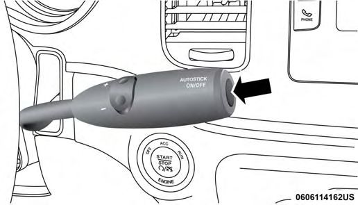
䡵 AUTOSTICK . . . . . . . . . . . . . . . . . . . . . . . . . . . .35
▫ AutoStick Operation . . . . . . . . . . . . . . . . . . . . .3628 STARTING AND OPERATING
AUTOMATIC TRANSMISSION
WARNING! (Continued)
WARNING! • Never leave children alone in a vehicle, or with
access to an unlocked vehicle. Allowing children to
• It is dangerous to shift out of PARK or NEUTRAL if be in a vehicle unattended is dangerous for a number
the engine speed is higher than idle speed. If your of reasons. A child or others could be seriously or
foot is not firmly pressing the brake pedal, the fatally injured. Children should be warned not to
vehicle could accelerate quickly forward or in re- touch the parking brake, brake pedal or the trans-
verse. You could lose control of the vehicle and hit mission gear selector.
someone or something. Only shift into gear when the • Do not leave the key fob in or near the vehicle (or in
engine is idling normally and your foot is firmly a location accessible to children), and do not leave
pressing the brake pedal. the ignition in the ACC or ON/RUN mode. A child
• Unintended movement of a vehicle could injure could operate power windows, other controls, or
those in or near the vehicle. As with all vehicles, you move the vehicle.
should never exit a vehicle while the engine is
running. Before exiting a vehicle, always come to a CAUTION!
complete stop, then apply the parking brake, shift
the transmission into PARK, and turn the ignition Damage to the transmission may occur if the following
OFF. When the ignition is in the OFF mode, the precautions are not observed:
transmission is locked in PARK, securing the vehicle • Shift into or out of PARK or REVERSE only after the
against unwanted movement. vehicle has come to a complete stop.
• When exiting the vehicle, always make sure the • Do not shift between PARK, REVERSE, NEUTRAL,
ignition is in the OFF mode, remove the key fob from or DRIVE when the engine is above idle speed.
the vehicle, and lock the vehicle. • Before shifting into any gear, make sure your foot is
firmly pressing the brake pedal.
(Continued)STARTING AND OPERATING 29
NOTE: You must press and hold the brake pedal while You must press the brake pedal to move the gear selector
shifting out of PARK. out of PARK, (refer to “Brake/Transmission Shift Interlock
System” in this section). To drive, move the gear selector
Ignition Park Interlock
from PARK or NEUTRAL to the DRIVE position. Pull the
This vehicle is equipped with an Ignition Park Interlock gear selector toward you when shifting into REVERSE or
which requires the transmission to be in PARK before the PARK, or when shifting out of PARK.
ignition can be turned to the OFF mode. This helps the
driver avoid inadvertently leaving the vehicle without
5
placing the transmission in PARK. This system also locks
the transmission in PARK whenever the ignition is in the
OFF mode.
Brake/Transmission Shift Interlock System
This vehicle is equipped with a Brake Transmission Shift
Interlock system (BTSI) that holds the transmission gear
selector in PARK unless the brakes are applied. To shift the
transmission out of PARK, the ignition must be turned to
the ON/RUN mode (engine running or not) and the brake
pedal must be pressed.
Gear Selector
Five-Speed Automatic Transmission The electronically-controlled transmission adapts its shift
The transmission gear position display (located in the schedule based on driver inputs, along with environmental
instrument cluster) indicates the transmission gear range. and road conditions. The transmission electronics are self-
The gear selector is mounted on the right side of the calibrating; therefore, the first few shifts on a new vehicle
steering column.30 STARTING AND OPERATING
may be somewhat abrupt. This is a normal condition, and PARK (P)
precision shifts will develop within a few hundred miles This range supplements the parking brake by locking the
(kilometers). transmission. The engine can be started in this range.
Only shift from DRIVE to PARK or REVERSE when the Never attempt to use PARK while the vehicle is in motion.
accelerator pedal is released and the vehicle is stopped. Be Apply the parking brake when exiting the vehicle in this
sure to keep your foot on the brake pedal when shifting range.
between these gears.
When parking on a level surface, you may shift the
The transmission gear selector has only PARK, REVERSE, transmission into PARK first, and then apply the parking
NEUTRAL, and DRIVE shift positions. Manual shifts can brake.
be made using the AutoStick shift control (refer to
When parking on a hill, apply the parking brake before
“AutoStick” in this section for further information).
shifting the transmission to PARK, otherwise the load on
Gear Ranges the transmission locking mechanism may make it difficult
Do not depress the accelerator pedal when shifting from to move the gear selector out of PARK. As an added
PARK or NEUTRAL into another gear range. precaution, turn the front wheels toward the curb on a
downhill grade and away from the curb on an uphill grade.
NOTE: After selecting any gear range, wait a moment to
allow the selected gear to engage before accelerating. This When exiting the vehicle, always:
is especially important when the engine is cold. • Apply the parking brake
If there is a need to restart the engine, be sure to cycle the • Shift the transmission into PARK
ignition to the OFF position before restarting. Transmission • Turn the ignition OFF
gear engagement may be delayed after restarting the
engine if the ignition is not cycled to the OFF position first. • Remove the key fob from the vehicleSTARTING AND OPERATING 31
WARNING! WARNING! (Continued)
• Never use the PARK position as a substitute for the the transmission into PARK, and turn the ignition
parking brake. Always apply the parking brake fully OFF. When the ignition is in the OFF mode, the
when exiting the vehicle to guard against vehicle transmission is locked in PARK, securing the vehicle
movement and possible injury or damage. against unwanted movement.
• Your vehicle could move and injure you and others if • When leaving the vehicle, always make sure the
it is not in PARK. Check by trying to move the gear ignition is in the OFF mode, remove the key fob from
the vehicle, and lock the vehicle. 5
selector out of PARK with the brake pedal released.
Make sure the transmission is in PARK before exit- • Never leave children alone in a vehicle, or with
ing the vehicle. access to an unlocked vehicle. Allowing children to
• It is dangerous to shift out of PARK or NEUTRAL if be in a vehicle unattended is dangerous for a number
the engine speed is higher than idle speed. If your of reasons. A child or others could be seriously or
foot is not firmly pressing the brake pedal, the fatally injured. Children should be warned not to
vehicle could accelerate quickly forward or in re- touch the parking brake, brake pedal or the trans-
verse. You could lose control of the vehicle and hit mission gear selector.
someone or something. Only shift into gear when the • Do not leave the key fob in or near the vehicle (or in
engine is idling normally and your foot is firmly a location accessible to children), and do not leave
pressing the brake pedal. the ignition in the ACC or ON/RUN mode. A child
• Unintended movement of a vehicle could injure could operate power windows, other controls, or
those in or near the vehicle. As with all vehicles, you move the vehicle.
should never exit a vehicle while the engine is
running. Before exiting a vehicle, always come to a
complete stop, then apply the parking brake, shift
(Continued)32 STARTING AND OPERATING
REVERSE (R)
CAUTION!
This range is for moving the vehicle backward. Shift into
• Before moving the transmission gear selector out of REVERSE only after the vehicle has come to a complete
PARK, you must turn the ignition to the ON/RUN stop.
mode, and also press the brake pedal. Otherwise,
damage to the gear selector could result. NEUTRAL (N)
• DO NOT race the engine when shifting from PARK Use this range when the vehicle is standing for prolonged
or NEUTRAL into another gear range, as this can periods with the engine running. The engine may be
damage the drivetrain. started in this range. Apply the parking brake and shift the
transmission into PARK if you must exit the vehicle.
The following indicators should be used to ensure that you
have properly engaged the transmission into the PARK
WARNING!
position:
• When shifting into PARK, pull the gear selector toward Do not coast in NEUTRAL and never turn off the
you and move it all the way counterclockwise until it ignition to coast down a hill. These are unsafe practices
stops. that limit your response to changing traffic or road
conditions. You might lose control of the vehicle and
• Release the gear selector and make sure it is fully seated have a collision.
in the PARK gate.
• Look at the transmission gear position display and CAUTION!
verify that it indicates the PARK position (P).
Towing the vehicle, coasting, or driving for any other
• With brake pedal released, verify that the gear selector
reason with the transmission in NEUTRAL can cause
will not move out of PARK.
severe transmission damage.
(Continued)STARTING AND OPERATING 33
Secure Park Anti-Theft System
CAUTION! (Continued)
Refer to “Recreational Towing” in “Starting And Op- The Secure Park anti-theft system was designed to enable
erating” and “Towing A Disabled Vehicle” in “In Case law enforcement officers to leave their vehicles unattended
Of Emergency” for further information. with the engines running without the ability of the vehicle
to be driven away. This system utilizes the Brake Transmis-
DRIVE (D) sion Shift Interlock (BTSI) to prevent the transmission from
shifting out of park.
This range should be used for most city and highway
5
driving. It provides the smoothest upshifts and downshifts, Enabling and Disabling The System
and the best fuel economy. The transmission automatically
To enable or disable, press the Secure Park button located
upshifts through underdrive first, second and third gears,
on the back side of the steering wheel when the engine is
direct fourth gear and overdrive fifth gear. The DRIVE
running. The vehicle can be in any gear to enable. Either
position provides optimum driving characteristics under
center button located on the right rear or left rear of the
all normal operating conditions.
steering wheel may be used.
When frequent transmission shifting occurs (such as when
operating the vehicle under heavy loading conditions, in
hilly terrain, traveling into strong head winds, or while
towing a heavy trailer), use the AutoStick shift control
(refer to ⬙AutoStick⬙ in this section for further information)
to select a lower gear. Under these conditions, using a
lower gear will improve performance and extend transmis-
sion life by reducing excessive shifting and heat buildup.34 STARTING AND OPERATING
To Deactivate
When you press the Secure Park button, the vehicle will
search for a valid key fob. If a valid fob is present, the
system will be deactivated and disabled. The vehicle can
then be shifted out of Park.
NOTE: If a valid fob is not found, a message will indicate
that the fob was not found.
Transmission Limp Home Mode
Transmission function is monitored electronically for ab-
normal conditions. If a condition is detected that could
Secure Park Button (Back View Of Steering Wheel) result in transmission damage, Transmission Limp Home
Mode is activated. In this mode, the transmission remains
The instrument cluster will display a message indicating
in the current gear until the vehicle is brought to a stop.
when the system is Active or Off.
After the vehicle has stopped, the transmission will remain
NOTE: The normal radio functionality for the left-rear and in second gear regardless of which forward gear is selected.
right-rear center buttons (Preset advance and Audio Mode PARK, REVERSE, and NEUTRAL will continue to operate.
advance) are deactivated. The Malfunction Indicator Light (MIL) may be illuminated.
Limp Home Mode allows the vehicle to be driven to an
System Activated
authorized dealer for service without damaging the trans-
The system is activated as soon as the transmission is mission.
shifted into Park (when Secure Park has been previously
In the event of a momentary problem, the transmission can
enabled). If the brake is pressed after activation, a message
be reset to regain all forward gears by performing the
will be displayed that states the Secure Park is activated.
following steps:
Press the Secure Park button to disable.STARTING AND OPERATING 35
1. Stop the vehicle. • Vehicle speed is sufficiently high.
2. Shift the transmission into PARK. • The driver is not heavily pressing the accelerator.
3. Turn the ignition OFF. AUTOSTICK
4. Wait approximately 10 seconds. AutoStick is a driver-interactive transmission feature pro-
viding manual shift control, giving you more control of the
5. Restart the engine.
vehicle. AutoStick allows you to maximize engine braking,
6. Shift into the desired gear range. If the problem is no eliminate undesirable upshifts and downshifts, and im- 5
longer detected, the transmission will return to normal prove overall vehicle performance. This system can also
operation. provide you with more control during passing, city driv-
ing, cold slippery conditions, mountain driving, trailer
NOTE: Even if the transmission can be reset, we recom-
towing, and many other situations.
mend that you visit your authorized dealer at your earliest
possible convenience. Your authorized dealer has diagnos-
tic equipment to assess the condition of your transmission.
If the transmission cannot be reset, authorized dealer
service is required.
Overdrive Operation
The automatic transmission includes an electronically con-
trolled Overdrive (fifth gear). The transmission will auto-
matically shift into Overdrive if the following conditions
are present:
• The gear selector is in the DRIVE position.
AUTOSTICK ON/OFF Switch36 STARTING AND OPERATING
AutoStick Operation • You can start out, from a stop, in first or second gear.
Tapping (+) (at a stop) will allow starting in second gear.
When the gear selector is in the DRIVE position, the
Starting out in second gear can be helpful in snowy or
transmission will operate automatically, shifting between
icy conditions.
the five available gears. To activate AutoStick mode, push
and release the AUTOSTICK ON/OFF switch (on the end • In models with V6 engine, if the accelerator is fully
of the gear selector) at any time while in the DRIVE depressed, the transmission will downshift when pos-
position. When AutoStick is active, the current transmis- sible (based on vehicle speed and gear).
sion gear is displayed in the instrument cluster. • The transmission will automatically upshift near max
In AutoStick mode, pushing the AUTOSTICK up (+) or engine speed, if the higher gear will provide greater
down (-) switch allows you to select a higher or lower gear. acceleration.
Pushing the bottom of the switch (-) triggers a downshift • The system will ignore attempts to upshift at too low of
(unless it would cause engine overspeeding), and pushing a vehicle speed.
the top of the switch (+) triggers an upshift (unless it would
cause engine lugging). The transmission will remain in the • Transmission shifting will be more noticeable when
current gear until another upshift or downshift is chosen, AutoStick is enabled.
except as described below. To exit AutoStick mode, push and release the AUTOSTICK
• The transmission will automatically downshift as the ON/OFF switch. The transmission will now operate auto-
vehicle slows (to prevent engine lugging) and will matically; shifting between the five available gears. You
display the current gear. can shift in or out of AutoStick mode at any time without
taking your foot off the accelerator pedal.
• The transmission will automatically downshift to first
gear when coming to a stop. After a stop, the driver Shifting the transmission out of DRIVE will also disable
should manually upshift (+) the transmission as the AutoStick (and it will remain disabled on subsequent
vehicle is accelerated. DRIVE engagements).STARTING AND OPERATING 37
NOTE: This maneuver should ONLY be performed at a
CAUTION!
complete stop, since DRIVE engagement may be delayed if
the vehicle is moving. Extreme steering maneuvers may cause the electrically
driven pump to reduce or stop power steering assis-
WARNING! tance in order to prevent damage to the system. Normal
operation will resume once the system is allowed to
Do not downshift for additional engine braking on a
cool.
slippery surface. The drive wheels could lose their grip
and the vehicle could skid, causing a collision or 5
personal injury. If the “SERVICE POWER STEERING” message
and a flashing icon are displayed on the instru-
ELECTRO-HYDRAULIC POWER STEERING — AWD ment cluster screen, it indicates that the vehicle
MODELS ONLY needs to be taken to the dealer for service. It is
Your vehicle is equipped with an electro-hydraulic power likely the vehicle has lost power steering assistance. Refer
steering system that will give you good vehicle response to “Instrument Cluster Display” in “Getting To Know Your
and increased ease of maneuverability in tight spaces. The Instrument Panel” for further information.
system will vary its assist to provide light efforts while If the “POWER STEERING HOT” message and an icon are
parking and good feel while driving. If the electro- displayed on the instrument cluster screen, it indicates that
hydraulic power steering system experiences a fault that extreme steering maneuvers may have occurred, which
prevents it from providing power steering assist, then the caused an over temperature condition in the power steer-
system will provide mechanical steering capability. ing system. You will lose power steering assistance mo-
mentarily until the over temperature condition no longer
exists. Once driving conditions are safe, then pull over and
let vehicle idle for a few moments until the light turns off.38 STARTING AND OPERATING
Refer to “Instrument Cluster Display” in “Getting To Know
WARNING!
Your Instrument Panel” for further information.
NOTE: Fluid level should be checked on a level surface and
with the engine off to prevent injury from moving
• Even if power steering assistance is no longer opera- parts and to ensure accurate fluid level reading. Do not
tional, it is still possible to steer the vehicle. Under these overfill. Use only manufacturer’s recommended power
conditions there will be a substantial increase in steering steering fluid.
effort, especially at very low vehicle speeds and during
parking maneuvers.
CAUTION!
• If the condition persists, see your authorized dealer for
service. Do not use chemical flushes in your power steering
system as the chemicals can damage your power steer-
Power Steering Fluid Check ing components. Such damage is not covered by the
Checking the power steering fluid level at a defined service New Vehicle Limited Warranty.
interval is not required. The fluid should be checked at
every oil change or if a leak is suspected, abnormal noises
are apparent, and/or the system is not functioning as
anticipated. Coordinate inspection efforts through an au-
thorized dealer.STARTING AND OPERATING 39
VEHICLE LOADING
The load carrying capacity of your vehicle is shown on the
“Vehicle Certification Label.” This label is attached to the
rear of the driver’s door. Do not exceed the Gross Vehicle
Weight Rating (GVWR) or Gross Axle Weight Rating
(GAWR) specified on the label.
While the weights and capacities shown in these tables is
5
intended as supplemental loading information for passen-
ger and luggage, the “Vehicle Certification Label” contains
the most current load capacities and therefore, if different,
will supersede the data in these tables. Refer to the
Power Steering Fluid Reservoir Owner’s Manual for more information.
(Located Behind Wheel Liner)
If necessary, add fluid to restore to the proper indicated
level. With a clean cloth, wipe any spilled fluid from all
surfaces. Refer to “Fluids And Lubricants” in “Technical
Specifications” for further information.
Gross Vehicle Weight Rating (GVWR)
Charger Police Vehicles Gross Vehicle Weight Rating (GVWR)
3.6 Engine with RWD Z1A Sales Code 5,250 lbs (2 381 kg)
3.6 Engine with RWD and optional GVWR Z1B Sales Code 5,450 lbs (2 472 kg)
5.7 Engine with RWD Z1B Sales Code 5,450 lbs (2 472 kg)
5.7 Engine with AWD Z1F Sales Code 5,500 lbs (2 495 kg)IN CASE OF EMERGENCY
CONTENTS
䡵 FUSES . . . . . . . . . . . . . . . . . . . . . . . . . . . . . . . .42 䡵 GEAR SELECTOR OVERRIDE . . . . . . . . . . . . . . . .51
▫ Auxiliary Power Distribution Center — 䡵 TOWING A DISABLED VEHICLE . . . . . . . . . . . . .52
If Equipped . . . . . . . . . . . . . . . . . . . . . . . . . . .42
▫ All Wheel Drive (AWD) Models . . . . . . . . . . . . .54
䡵 JACKING AND TIRE CHANGING . . . . . . . . . . . .45 6
▫ Rear Wheel Drive (RWD) Models . . . . . . . . . . . .54
▫ Jack Location/Spare Tire Stowage . . . . . . . . . . .45
▫ Without The Key Fob . . . . . . . . . . . . . . . . . . . . .55
▫ Preparations For Jacking . . . . . . . . . . . . . . . . . .46
▫ Jacking And Changing A Tire . . . . . . . . . . . . . . .47
▫ Road Tire Installation . . . . . . . . . . . . . . . . . . . .5042 IN CASE OF EMERGENCY
FUSES Auxiliary Power Distribution Center — If Equipped
The Auxiliary Power Distribution Center is located in the
WARNING! trunk compartment on the passenger side. This module
• When replacing a blown fuse, always use an appro- contains fuses and relays. Fuse cavity location and descrip-
priate replacement fuse with the same amp rating as tions are printed on the inside of the power distribution
the original fuse. Never replace a fuse with another center cover.
fuse of higher amp rating. Never replace a blown
fuse with metal wires or any other material. Do not CAUTION!
place a fuse inside a circuit breaker cavity or vice • When installing the power distribution center cover,
versa. Failure to use proper fuses may result in it is important to ensure the cover is properly posi-
serious personal injury, fire and/or property damage. tioned and fully latched. Failure to do so may allow
• Before replacing a fuse, make sure that the ignition is water to get into the power distribution center and
off and that all the other services are switched off possibly result in an electrical system failure.
and/or disengaged. • When replacing a blown fuse, it is important to use
• If the replaced fuse blows again, contact an autho- only a fuse having the correct amperage rating. The
rized dealer. use of a fuse with a rating other than indicated may
• If a general protection fuse for safety systems (air result in a dangerous electrical system overload. If a
bag system, braking system), power unit systems properly rated fuse continues to blow, it indicates a
(engine system, transmission system) or steering problem in the circuit that must be corrected.
system blows, contact an authorized dealer.IN CASE OF EMERGENCY 43 Cavity Mini-Fuse Description F1 5 Amp Tan Front Corner LEDs F2 5 Amp Tan Grill LEDs F3 5 Amp Tan Mirror LEDs F4 2 Amp Gray Visor Trigger F7 5 Amp Tan B Pillar LEDs F8 5 Amp Tan Deck LEDs F9 2 Amp Gray Takedown 6 F10 2 Amp Gray Right Alley F11 2 Amp Gray Left Alley F12 2 Amp Gray Lightbar Front F13 2 Amp Gray Lightbar Rear F14 2 Amp Gray Taillamp Flash F15 2 Amp Gray Headlamp Flash F16 5 Amp Tan Rear LEDs F17 5 Amp Tan Gun Lock F18 2 Amp Gray T/A Left F19 2 Amp Gray T/A Right F20 2 Amp Gray T/A Flash F21 20 Amp Yellow Siren In 1A F22 20 Amp Yellow Siren In 1B
44 IN CASE OF EMERGENCY

            Cavity          Mini-Fuse          Description
             F23          20 Amp Yellow         Siren In 2A
             F24          20 Amp Yellow         Siren In 2B
             F25          20 Amp Yellow        Front Radio
             F26          20 Amp Yellow         Rear Radio
             F27           10 Amp Red              Radar
             F28          30 Amp Green            Lightbar
             F29           15 Amp Blue              Visor
             F30           15 Amp Blue              T/A
             F31          20 Amp Yellow      Siren Controller
             F32            5 Amp Tan          Front Radio
             F34            5 Amp Tan     Fan/Timer Module Ign
             F36           15 Amp Blue           Computer
             F37           10 Amp Red             Camera
             F38           10 Amp Red             Modem
             F39            5 Amp Tan              Printer
IN CASE OF EMERGENCY 45
JACKING AND TIRE CHANGING Jack Location/Spare Tire Stowage
The jack and spare tire are both stowed in the trunk. Follow
WARNING! these steps to access the jack and spare tire.
• Do not attempt to change a tire on the side of the NOTE: The spare tire must be removed in order to access
vehicle close to moving traffic. Pull far enough off the jack.
the road to avoid the danger of being hit when
operating the jack or changing the wheel. 1. Open the trunk.
• Being under a jacked-up vehicle is dangerous. The 2. Rotate the fastener securing the spare tire counterclock-
vehicle could slip off the jack and fall on you. You wise to remove it. 6
could be crushed. Never put any part of your body
under a vehicle that is on a jack. If you need to get 3. Remove the spare tire.
under a raised vehicle, take it to a service center 4. Rotate the fastener securing the jack and wheel chocks
where it can be raised on a lift. counterclockwise to remove it.
• Never start or run the engine while the vehicle is on
a jack.
• The jack is designed to be used as a tool for changing
tires only. The jack should not be used to lift the
vehicle for service purposes. The vehicle should be
jacked on a firm level surface only. Avoid ice or
slippery areas.46 IN CASE OF EMERGENCY
WARNING! (Continued)
• Always stow the jack parts and the spare tire in the
places provided. Have the deflated (flat) tire repaired
or replaced immediately.
Preparations For Jacking
1. Park the vehicle on a firm, level surface as far from the
edge of the roadway as possible. Avoid icy or slippery
areas.
WARNING!
Jack Fastener
Do not attempt to change a tire on the side of the
5. Remove the scissors jack and lug wrench from the spare vehicle close to moving traffic, pull far enough off the
wheel as an assembly. Turn the jack screw to the left to road to avoid being hit when operating the jack or
loosen the lug wrench, and remove the wrench from the changing the wheel.
jack assembly.
2. Turn on the Hazard Warning flasher.
WARNING!
3. Apply the parking brake.
• A loose tire or jack thrown forward in a collision or
4. Place the gear selector into PARK.
hard stop could endanger the occupants of the ve-
hicle. 5. Turn off the ignition.
(Continued)IN CASE OF EMERGENCY 47
6. Block both the front and rear of the wheel diagonally
WARNING! (Continued)
opposite of the jacking position using
the provided wheel chocks. For ex- • Never start or run the engine with the vehicle on a
ample, if changing the right front tire, jack.
chock the left rear wheel. Place both • Do not let anyone sit in the vehicle when it is on a
chocks under the tire. jack.
• Do not get under the vehicle when it is on a jack. If
NOTE: Passengers should not remain in the vehicle when you need to get under a raised vehicle, take it to a
the vehicle is being jacked. service center where it can be raised on a lift.
Jacking And Changing A Tire • Only use the jack in the positions indicated and for 6
lifting this vehicle during a tire change.
WARNING! • If working on or near a roadway, be extremely
careful of motor traffic.
Carefully follow these tire changing warnings to help • To assure that spare tires, flat or inflated, are securely
prevent personal injury or damage to your vehicle: stowed, spares must be stowed with the valve stem
• Always park on a firm, level surface as far from the facing the ground.
edge of the roadway as possible before raising the
vehicle.
• Turn on the Hazard Warning flasher.
• Chock the wheel diagonally opposite the wheel to be
raised.
• Apply the parking brake firmly and set an automatic
transmission in PARK.
(Continued)48 IN CASE OF EMERGENCY
3. Place the jack underneath the lift area that is closest to
the flat tire. Turn the jack screw clockwise to firmly
engage the jack saddle with the lift area of the sill flange.
Jack Warning Label
CAUTION!
Do not attempt to raise the vehicle by jacking on Front Jacking Location
locations other than those indicated in the Jacking
Instructions for this vehicle.
1. Remove the spare tire, wheel chocks, jack, and lug
wrench.
2. Before raising the vehicle, use the lug wrench to loosen,
but not remove, the lug nuts on the wheel with the flat
tire. Turn the lug nuts counterclockwise one turn while
the wheel is still on the ground.IN CASE OF EMERGENCY 49
6. Mount the spare tire.
CAUTION!
Be sure to mount the spare tire with the valve stem
facing outward. The vehicle could be damaged if the
spare tire is mounted incorrectly.
NOTE: Refer to “Tires—General Information” in the Own-
er’s Manual for additional warnings, cautions, and infor-
mation about the spare tire, its use, and operation. 6
7. Install the lug nuts with the cone shaped end of the lug
Rear Jacking Location nut toward the wheel. Lightly tighten the lug nuts.
4. Raise the vehicle just enough to remove the flat tire and
install the spare tire. WARNING!
To avoid the risk of forcing the vehicle off the jack, do
WARNING! not tighten the wheel nuts fully until the vehicle has
Raising the vehicle higher than necessary can make the been lowered. Failure to follow this warning may
vehicle less stable. It could slip off the jack and hurt result in serious injury.
someone near it. Raise the vehicle only enough to 8. Lower the vehicle to the ground by turning the jack
remove the tire. handle counterclockwise.
5. Remove the lug nuts and tire. 9. Finish tightening the lug nuts. Push down on the
wrench while at the end of the handle for increased
leverage. Tighten the lug nuts in a star pattern until each50 IN CASE OF EMERGENCY
nut has been tightened twice. Refer to “Torque Specifi-
WARNING!
cations” in “Technical Specifications” for proper lug nut
torque. If in doubt about the correct tightness, have To avoid the risk of forcing the vehicle off the jack, do
them checked with a torque wrench by your authorized not tighten the wheel nuts fully until the vehicle has
dealer or at a service station. been lowered. Failure to follow this warning may
result in serious injury.
10. Stow the wheel chocks, jack, tools and flat tire. Make
sure the base of the jack faces the back of the vehicle 3. Lower the vehicle to the ground by turning the jack
before tightening down the fastener. handle counterclockwise.
WARNING! 4. Refer to “Torque Specifications” in “Technical Specifica-
tions” for proper lug nut torque.
A loose tire or jack thrown forward in a collision or
hard stop could endanger the occupants of the vehicle. 5. After 25 miles (40 km), check the lug nut torque with a
Always stow the jack parts and the spare tire in the torque wrench to ensure that all lug nuts are properly
places provided. Have the deflated (flat) tire repaired seated against the wheel.
or replaced immediately. Vehicles Equipped With Wheel Covers
Road Tire Installation 1. Mount the road tire on the axle. For vehicles equipped
with center caps, proceed to Step 4.
1. Mount the road tire on the axle.
2. Install two lug nuts on the mounting studs, which are on
2. Install the remaining lug nuts with the cone shaped end
each side of the stud that is in alignment with the valve
of the nut toward the wheel. Lightly tighten the lug
stem. Install the lug nuts with the cone shaped end of
nuts.
the nut toward the wheel. Lightly tighten the lug nuts.IN CASE OF EMERGENCY 51
To avoid the risk of forcing the vehicle off the jack, do 7. Stow the wheel chocks, jack, tools, and spare tire. Make
not tighten the lug nuts fully until the vehicle is lowered sure the base of the jack faces the back of the vehicle
to the ground. before tightening down the fastener.
3. Install the remaining lug nuts with the cone shaped end
of the nut toward the wheel. Lightly tighten the lug
WARNING!
nuts. To avoid the risk of forcing the vehicle off the jack, A loose tire or jack thrown forward in a collision or
do not tighten the lug nuts fully until the vehicle is hard stop, could endanger the occupants of the vehicle.
lowered to the ground. Always stow the jack parts and the spare tire in the
4. Lower the vehicle to the ground by turning the jack places provided. 6
handle counterclockwise.
GEAR SELECTOR OVERRIDE
5. Finish tightening the lug nuts. Push down on the
wrench while tightening for increased leverage. Alter- If a malfunction occurs and the gear selector cannot be
nate lug nuts until each nut has been tightened twice. moved out of the PARK position, you can use the following
Refer to “Torque Specifications” in “Technical Specifica- procedure to temporarily move the gear selector:
tions” for proper lug nut torque. If in doubt about the 1. Turn the engine OFF
correct tightness, have them checked with a torque
wrench by your authorized dealer or at a service station. 2. Firmly apply the parking brake.
6. For vehicles equipped with center caps, install the center 3. Tilt the steering wheel to the full up position.
cap by hand. Do not use a hammer or excessive force to 4. Press and maintain firm pressure on the brake pedal.
install the center cap.
5. Insert a screwdriver or similar tool into the access port
(ringed circle) on the knee bolster located below the
steering column, push and hold the override release
lever up.52 IN CASE OF EMERGENCY
7. The vehicle may then be started in NEUTRAL.
TOWING A DISABLED VEHICLE
This section describes procedures for towing a disabled
vehicle using a commercial towing service.
Gear Selector Override Location
6. Move the gear selector to the NEUTRAL position.
Towing Condition Wheels OFF The Ground RWD MODELS AWD MODELS
Flat Tow NONE If transmission is NOT ALLOWED
operable:
• Transmission in
NEUTRAL
• 30 mph (48 km/h)
max speed
• 15 miles (24 km)
max distanceIN CASE OF EMERGENCY 53
Wheel Lift or Dolly Tow Front NOT RECOMMENDED NOT ALLOWED
(but, if used, same limita-
tions as above)
Rear NOT RECOMMENDED NOT RECOMMENDED,
but, if used:
• Ignition in ON/RUN
position
• Transmission in NEU-
TRAL (NOT in PARK!)
6
Flatbed ALL BEST METHOD BEST METHOD
Proper towing or lifting equipment is required to prevent for instructions on shifting the transmission out of PARK
damage to your vehicle. Use only tow bars and other for towing.
equipment designed for this purpose, following equipment
manufacturer’s instructions. Use of safety chains is man- CAUTION!
datory. Attach a tow bar or other towing device to main
structural members of the vehicle, not to bumpers or • DO NOT use sling-type equipment when towing.
associated brackets. State and local laws regarding vehicles Vehicle damage may occur.
under tow must be observed. • When securing the vehicle to a flatbed truck, do not
attach to front or rear suspension components. Dam-
If you must use the accessories (wipers, defrosters, etc.) age to your vehicle may result from improper towing.
while being towed, the ignition must be in the ON/RUN • The manufacturer does not recommend towing this
mode, not the ACC mode. vehicle using a tow dolly. Vehicle damage may occur.
If the key fob is unavailable, or the vehicle’s battery is
discharged, refer to ⬙Gear Selector Override⬙ in this sectionYou can also read