Clavister Lynx X8 Getting Started Guide
←
→
Page content transcription
If your browser does not render page correctly, please read the page content below

Clavister Lynx X8
Getting Started Guide
                               Clavister AB
                               Sjögatan 6J
                     SE-89160 Örnsköldsvik
                                  SWEDEN

                   Phone: +46-660-299200
                       www.clavister.com

                     Published 2015-04-07
              Copyright © 2015 Clavister AB
Clavister Lynx X8
Getting Started Guide
Published 2015-04-07

Copyright © 2015 Clavister AB

Copyright Notice

This publication, including all photographs, illustrations and software, is protected under
international copyright laws, with all rights reserved. Neither this manual, nor any of the material
contained herein, may be reproduced without the written consent of Clavister.

Disclaimer

The information in this document is subject to change without notice. Clavister makes no
representations or warranties with respect to the contents hereof and specifically disclaims any
implied warranties of merchantability or fitness for a particular purpose. Clavister reserves the
right to revise this publication and to make changes from time to time in the content hereof
without any obligation to notify any person or parties of such revision or changes.

Limitations of Liability

UNDER NO CIRCUMSTANCES SHALL CLAVISTER OR ITS SUPPLIERS BE LIABLE FOR DAMAGES OF
ANY CHARACTER (E.G. DAMAGES FOR LOSS OF PROFIT, SOFTWARE RESTORATION, WORK
STOPPAGE, LOSS OF SAVED DATA OR ANY OTHER COMMERCIAL DAMAGES OR LOSSES)
RESULTING FROM THE APPLICATION OR IMPROPER USE OF THE CLAVISTER PRODUCT OR
FAILURE OF THE PRODUCT, EVEN IF CLAVISTER IS INFORMED OF THE POSSIBILITY OF SUCH
DAMAGES. FURTHERMORE, CLAVISTER WILL NOT BE LIABLE FOR THIRD-PARTY CLAIMS AGAINST
CUSTOMER FOR LOSSES OR DAMAGES. CLAVISTER WILL IN NO EVENT BE LIABLE FOR ANY
DAMAGES IN EXCESS OF THE AMOUNT CLAVISTER RECEIVED FROM THE END-USER FOR THE
PRODUCT.

                                           2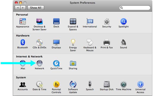
Table of Contents
      Preface ................................................................................................................ 5
      1. X8 Product Overview ......................................................................................... 7
             1.1. Unpacking the X8 .................................................................................... 7
             1.2. Interfaces and Ports ................................................................................. 9
      2. Registering with Clavister .................................................................................. 12
      3. X8 Installation .................................................................................................. 17
             3.1. General Installation Guidelines ................................................................. 17
             3.2. DIN Rail Installation ................................................................................ 19
             3.3. Local Console Port Connection ................................................................. 20
             3.4. Connecting Power .................................................................................. 22
      4. cOS Core Configuration ..................................................................................... 25
             4.1. Management Workstation Connection ...................................................... 25
             4.2. Web Interface and Wizard Setup ............................................................... 28
             4.3. Manual Web Interface Setup .................................................................... 36
             4.4. CLI Setup .............................................................................................. 52
             4.5. License Installation Methods .................................................................... 60
             4.6. Setup Troubleshooting ........................................................................... 62
             4.7. Going Further with cOS Core .................................................................... 64
      5. Resetting to Factory Defaults .............................................................................. 67
      6. Warranty Service .............................................................................................. 69
      7. Safety Precautions ............................................................................................ 71
      A. X8 Specifications .............................................................................................. 74
      B. Declarations of Conformity ................................................................................ 75
      C. Windows XP IP Setup ........................................................................................ 77
      D. Windows Vista IP Setup ..................................................................................... 79
      E. Windows 7 IP Setup .......................................................................................... 81
      F. Windows 8 IP Setup .......................................................................................... 83
      G. Apple Mac IP Setup .......................................................................................... 85

                                                              3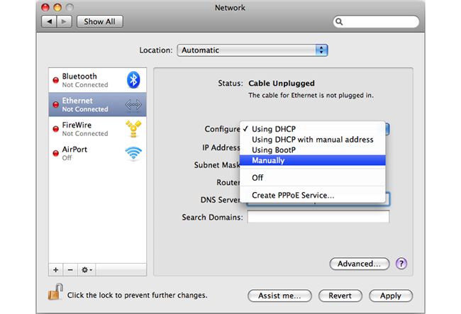
List of Figures
       1.1. An Unpacked Clavister X8 Appliance .................................................................. 7
       1.2. Front View of the Clavister X8 ............................................................................ 9
       1.3. X8 Status LEDs ............................................................................................... 10
       3.1. The X8 Rear Showing DIN Attachment ............................................................... 19
       3.2. The X8 Local Console Port ............................................................................... 20
       3.3. X8 Power Inlet Socket ..................................................................................... 22
       3.4. Connection Diagram for the Optional X8 Euroblock ............................................. 22

                                                             4
Preface
    Target Audience

    The target audience for this guide is the administrator who has taken delivery of a packaged
    Clavister X8 appliance and is setting it up for the first time. The guide takes the user from
    unpacking and installation of the device through to power-up, including network connections
    and initial cOS Core configuration.

    Text Structure

    The text is divided into chapters and subsections. Numbered subsections are shown in the table
    of contents at the beginning of the document.

    Notes to the main text

    Special sections of text which the reader should pay special attention to are indicated by icons
    on the left hand side of the page followed by a short paragraph in italicized text. There are the
    following types of such sections:

                Note
                This indicates some piece of information that is an addition to the preceding text. It may
                concern something that is being emphasized or something that is not obvious or
                explicitly stated in the preceding text.

                Tip
                This indicates a piece of non-critical information that is useful to know in certain
                situations but is not essential reading.

                Caution
                This indicates where the reader should be careful with their actions as an undesirable
                situation may result if care is not exercised.

                Important
                This is an essential point that the reader should read and understand.

                Warning
                This is essential reading for the user as they should be aware that a serious situation
                may result if certain actions are taken or not taken.

                                               5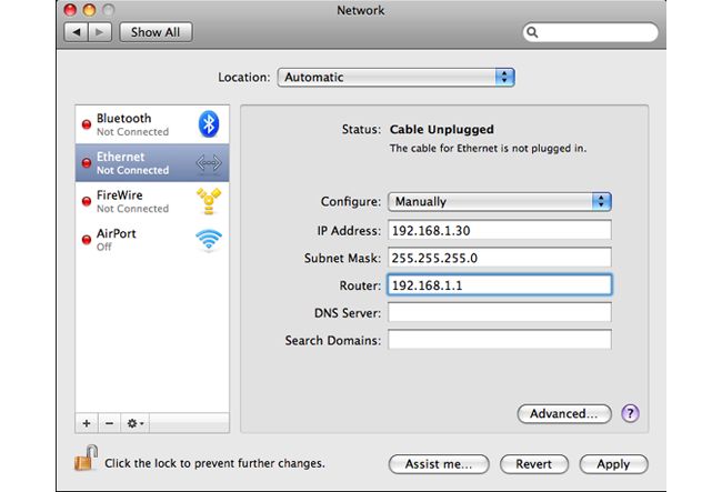
Preface

Text links

Where a "See section" link is provided in the main text, this can be clicked on to take the reader
directly to that reference. For example, see Section 4.6, “Setup Troubleshooting ”.

Web links

Web links included in the document are clickable. For example, http://www.clavister.com.

Trademarks

Certain names in this publication are the trademarks of their respective owners.

cOS Core is the trademark of Clavister AB.

Windows, Windows XP, Windows Vista and Windows 7 are either registered trademarks or
trademarks of Microsoft Corporation in the United States and/or other countries.

Apple, Mac and Mac OS are trademarks of Apple Inc. registered in the United States and/or other
countries.

                                             6
Chapter 1: X8 Product Overview

     • Unpacking the X8, page 7

     • Interfaces and Ports, page 9

     The Clavister Lynx X8 is a ruggedized hardware platform for cOS Core with no moving parts and
     long MTBF. The X8 is designed for industrial applications where there is a need for extreme
     durability and performance. It is fanless, dustproof, has no interior wires and can tolerate a large
     range of operating temperatures as well as being DIN rail mountable.

1.1. Unpacking the X8

                             Figure 1.1. An Unpacked Clavister X8 Appliance

     This section details the unpacking of the X8 appliance. Open the packaging box used for
     shipping and carefully unpack the contents. The delivered product packaging should contain the
     following:

     •   The Clavister X8 appliance.

                                                7
Chapter 1: X8 Product Overview

•   RS-232 local console cable.

•   Power cable.

•   Euroblock (Phoenix) plug for optional power rail connection.

             Note: If any items are missing
             If any items are missing from the X8 package, please contact the reseller or distributor.
             All relevant documentation in PDF format can be downloaded from the Clavister
             website and is included in the ZIP file distributions of new cOS Core versions.

Downloadable X8 Documentation

All documentation and other resources for the X8, including this guide, can be downloaded from
the X8 product page which can be found at http://www.clavister.com/start.

End of Life Treatment

The X8 appliance is marked with the European Waste Electrical and Electronic Equipment (WEEE)
directive symbol which is shown below.

The product, and any of its parts, should not be discarded of by means of regular refuse disposal.
At end-of-life, the product and parts should be given to an appropriate service that deals with
the removal of such specialist materials.

                                           8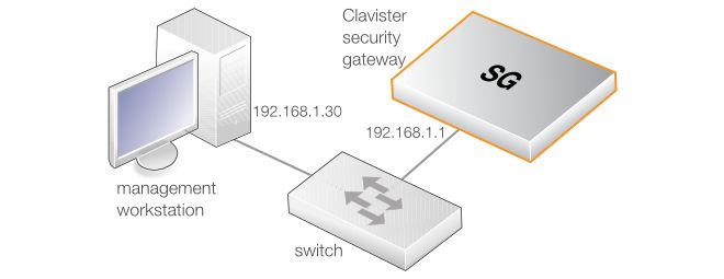
Chapter 1: X8 Product Overview

1.2. Interfaces and Ports
      This section is an overview of the X8 product's external design.

                                 Figure 1.2. Front View of the Clavister X8

      The X8 features a number of connection ports on the front panel:

      •   4 x RJ45 Gigabit Ethernet interfaces. These have the logical cOS Core names G1, G2, G3 and
          G4. The names are written by the side of each interface. They function independently of each
          other and are not connected by a switch fabric.

          These connections are capable of link speed auto-negotiation and can operate using
          10Base-T, 100Base-Tx, or 1000Base-T.

      •   An RJ45 RS-232 console connection. This port is used for direct access to the cOS Core Boot
          Menu and the cOS Core Command Line Interface (CLI).

      All the X8 Ethernet interfaces support Automatic MDI-X and do not require a crossover cable for
      direct connection from another computer.

      The full connection capabilities of all X8 Ethernet interfaces are listed in Appendix A, X8
      Specifications.

      Under the console port at the bottom of the front panel are two indicator LEDs:

      •   The right hand LED indicates power and is either dark or green. If power is applied to the unit,
          the LED is green.

                                                 9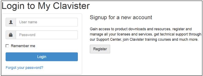
Chapter 1: X8 Product Overview

•   The left hand LED indicates cOS Core status and can be either of the following colors:

    i.    Green - cOS Core is operating normally.

    ii.   Red - An error condition has occurred and cOS Core is not fully functioning. This is
          usually a result of cOS Core entering lockdown mode because there is no valid software
          license.

                                   Figure 1.3. X8 Status LEDs

                                          10
Chapter 1: X8 Product Overview 11
Chapter 2: Registering with Clavister

    Before applying power to the X8 and starting cOS Core, it is important to understand the the
    customer and product registration procedures. There are two types of registration:

    •    Registering as a Clavister Customer

         This involves registering basic contact and company information on the Clavister website
         and establishing login credentials. Later, these credentials can also be used by cOS Core for
         automatically registering the X8 hardware unit and automatically downloading the correct
         license.

         This is is a mandatory requirement for all new customers and needs to be done only once. A
         description of doing this can be found below. Even if registration is not done before starting
         the cOS Core wizard, the wizard will provide a link to the registration page so it can be done
         while the wizard is running.

    •    Registration of the X8 Hardware Unit

         This is mandatory for every hardware unit before a license can be downloaded. It can be
         done in the following ways:

         i.      Automatic registration after cOS Core starts - This can done by the Setup Wizard
                 which starts automatically in a browser popup window when cOS Core Web Interface is
                 started for the first time. The wizard is described in Section 4.2, “Web Interface and Wizard
                 Setup”.

         ii.     Manual registration of the X8 on the Clavister website - This is described in the last
                 half of this section. Manual registration may be necessary if the X8 does not have
                 Internet access.

    A. Registering as a Clavister Customer

    The X8 registration steps for a first time user of Clavister hardware are as follows:

    1.        Open a web browser, surf to http://www.clavister.com and select Log in.

                                                   12
Chapter 2: Registering with Clavister
2. The customer login page is presented. It is assumed that a new customer is accessing the
site for the first time so they should press the Register button. If already registered, log in
and skip to step 8.
3. The registration webpage is now presented. The required information should be filled in. In
the example below, a user called John Smith registers. It is important to enter the
administrator's company details as well. Without company details, a license cannot be
created.
4. When the registration details are accepted, an email is sent to the email address given so
that the registration can be confirmed.
13Chapter 2: Registering with Clavister
5. Below is an example of the email that John Smith would receive.
6. When the confirmation link in the email is clicked, the new customer is taken to a webpage
to indicate that confirmation has been successful. They should now log in to the Clavister
website with the credentials they have submitted during registration.
7. After logging in, the website toolbar will show the name of the currently logged in
customer.
14Chapter 2: Registering with Clavister
B. Registration of the X8 Hardware Unit
These steps describe manual registration of the X8 hardware unit.
Alternatively, if the X8 is connected to the Internet then this registration can be also be
performed automatically by the cOS Core Setup Wizard which will appear as a browser popup
window in the Web Interface when cOS Core starts for the first time.
1. Log in to the Clavister website and select the Register License option.
2. The registration page is displayed. Under the tab Hardware Serial Number and Service
Tag, enter the Hardware Serial Number and Service Tag must be entered. These two codes
are found on a label which should be attached to the X8 hardware itself. The label is
usually found on the hardware's underside but may by found in another position.
15Chapter 2: Registering with Clavister
The image above shows an example label which illustrates the typical layout of identification
labels found on Clavister hardware products.
After Successful Hardware Registration
Once the X8 hardware unit is registered, a cOS Core license for the unit becomes available for
download and installation from Clavister servers. This installation can be done automatically
through the cOS Core Setup Wizard which is described in Section 4.2, “Web Interface and Wizard
Setup”.
If the X8 is not connected to the Internet, the license must be manually downloaded from the
cOS Core website and then manually uploaded.
All license installation options are listed and discussed in Section 4.5, “License Installation
Methods”.
16Chapter 3: X8 Installation
• General Installation Guidelines, page 17
• DIN Rail Installation, page 19
• Local Console Port Connection, page 20
• Connecting Power, page 22
3.1. General Installation Guidelines
Follow these geneneral guidelines when installing your Clavister X8 appliance:
• Safety
Take notice of the safety guidelines laid out in Chapter 7, Safety Precautions. These are
specified in multiple languages.
• Power
Make sure that the power source circuits are properly grounded and then use the power cord
supplied with the appliance to connect it to the power source.
• Using Other Power Cords
If your installation requires a different power cord than the one supplied with the appliance,
be sure to use a cord displaying the mark of the safety agency that defines the regulations for
power cords in your country. Such marks are an assurance that the cord is safe.
• Power Overload
Ensure that the appliance does not overload the power circuits, wiring and over-current
protection.
To determine the possibility of overloading the supply circuits, add together the ampere
ratings of all devices installed on the same circuit as the appliance and compare the total
with the rating limit for the circuit. The maximum ratings for the X8 are listed in Appendix A,
X8 Specifications.
• Surge Protection
A third party surge protection device should be considered and is strongly recommended as
17Chapter 3: X8 Installation
a means to prevent electrical surges reaching the appliance. This is mentioned again in
Section 3.4, “Connecting Power”.
• Temperature
Do not install the appliance in an environment where the ambient temperature during
operation might fall outside the specified operating range. This range is documented in
Appendix A, X8 Specifications.
The intended operating temperature range is "room temperature". That is to say, the
temperature most commonly found in a modern office and in which humans feel
comfortable. This is usually considered to be between 20 and 25 degrees Celsius (68 to 77
degrees Fahrenheit). Special rooms for computer equipment may use a lower range and this
is also acceptable.
• Airflow
Make sure that airflow around the appliance is not restricted.
Note: The specifications appendix provides more details
Detailed information concerning power supply range, operating temperature range and
other operating details can be found at the end of this publication in Appendix A, X8
Specifications.
18Chapter 3: X8 Installation
3.2. DIN Rail Installation
The X8 is designed for DIN rail mounting only and comes delivered with a rotatable DIN bracket
at the back for mounting. This DIN bracket can be rotated in 90 degree increments and can be
easily removed if not needed. The DIN bracket is shown in the image below.
Figure 3.1. The X8 Rear Showing DIN Attachment
Warning: The X8 should not operate on a flat surface
Since all cooling in the X8 is achieved through heat exchange between the unit's sides
and the surrounding air, it must not be placed on a flat surface, such as a table, during
operation.
19Chapter 3: X8 Installation
3.3. Local Console Port Connection
The local console port is a physical RS-232 port on the X8 hardware.
Figure 3.2. The X8 Local Console Port
This local console port allows direct management connection to the appliance, either from a
separate computer running console emulation software or from a console terminal. Local
console access can then be used for both management of cOS Core with CLI commands or to
enter the boot menu in order to access X8 firmware loader options.
Tip: Skip the rest of this section if using the Web Interface
This rest of this section can be initially skipped if cOS Core setup is going to be done with
the cOS Core Web Interface since neither boot menu or CLI access will be needed.
Issuing CLI Commands
CLI commands can be issued via the local console port for both initial cOS Core setup as well as
for ongoing system administration.
The local console port need not be used if setup is done through a web browser as described in
Section 4.2, “Web Interface and Wizard Setup”. If the local console port is used for setup, no
password is initially needed and the CLI commands required are described in Section 4.4, “CLI
Setup”.
Note: Setting a local console password is recommended
A local console password need not be set. However, if it is not, anyone with physical
access to the local console will have full administrator rights.
Unless the hardware is placed in a secure area, it is therefore recommended to set a local
console password. This is done by entering the console boot menu at system startup by
pressing any console key before cOS Core has fully started. The boot menu and its
options is discussed further in the separate cOS Core Administrators Guide.
Requirements for Local Console Connection
To get management access via the local console port, the following is needed:
20Chapter 3: X8 Installation
• A terminal or a computer with a serial port and the ability to emulate a terminal (for example,
the open source puTTY software).
• The terminal console should have the following settings:
i. 9600 bps.
ii. No parity.
iii. 8 bits.
iv. 1 stop bit.
v. No flow control.
• An RS-232 cable with appropriate terminating connectors.
Connection Steps
To connect a terminal to the local console port, perform the following steps:
1. Check that the console connection settings are configured as described above.
2. Connect one of the connectors on the cable directly to the local console port on the X8.
3. Connect the other end of the cable to a console terminal or to the serial connector of a
computer running console emulation software.
Connection Using SSH
An alternative to using the local console port for CLI access is to connect via a physical Ethernet
interface and using a Secure Shell (SSH) client on the management workstation to issue CLI
commands. This is discussed further in Section 4.1, “Management Workstation Connection”.
21Chapter 3: X8 Installation
3.4. Connecting Power
This section describes connecting power. As soon as power is applied, the X8 will boot-up and
cOS Core will start.
Important
Please review the electrical safety information in Chapter 7, Safety Precautions.
Connecting AC Power
To connect power, follow these steps:
1. Plug the end of the power adapter's power cord into the power inlet socket on the X8. The
X8 uses a Euroblock power connection (also known as a Phoenix connection). The power
plug inserts into the bottom of the unit and is screwed in to provide a secure cable
connection. Two options exist for the power connection:
i. Use the supplied cable to connect to a standard power outlet socket.
ii. Alternatively, the supplied accessory Euroblock connector can be used to connect to a
power rail that provides power within acceptable limits (see Appendix A, X8
Specifications). A wiring diagram for the connector is shown below.
Figure 3.3. X8 Power Inlet Socket
Figure 3.4. Connection Diagram for the Optional X8 Euroblock
22Chapter 3: X8 Installation
3. With the supplied power cable, plug the other end of the power cord into a power outlet.
There is no On/Off switch. If using a power rail to supply power, switch on the power.
4. The X8 will boot up and cOS Core will start. After a brief period of time, cOS Core will be
initialized and the X8 appliance is ready for configuration from a management workstation
using either the Web Interface or the Command Line Interface (CLI) as the management
interface.
Initial configuration is discussed in detail in Chapter 4, cOS Core Configuration.
Important: Protecting Against Power Surges
It is recommended that the purchase and use of a separate surge protection unit from a
third party is considered for the power connection to the X8 hardware. This is to ensure
that the X8 is protected from damage by sudden external electrical power surges
through the power cable.
Surge protection is particularly important in locations where there is a heightened risk of
lightning strikes and/or power grid spikes.
Any surge protection unit should be installed exactly according to the manufacturer's
instructions since correct installation of such units is vital for them to be effective.
23Chapter 3: X8 Installation 24
Chapter 4: cOS Core Configuration

     • Management Workstation Connection, page 25

     • Web Interface and Wizard Setup, page 28

     • Manual Web Interface Setup, page 36

     • CLI Setup, page 52

     • License Installation Methods, page 60

     • Setup Troubleshooting , page 62

     • Going Further with cOS Core, page 64

4.1. Management Workstation Connection
     cOS Core Starts After Power Up

     It is assumed that the X8 unit is now unpacked, positioned correctly and powered is applied. If
     not, the earlier chapters in this manual should be referred to before continuing.

     Clavister's cOS Core network security operating system is preloaded on the X8 and will
     automatically boot up after power is applied. After boot-up is complete, an external
     management computer workstation can be used to configure cOS Core.

     The Default Management Interface

     After first time startup, cOS Core automatically makes management access available on a single
     predefined Ethernet interface and assigns the private IPv4 address 192.168.1.1 to it.

     For the X8, the default management interface is the G1 interface.

     cOS Core Setup Methods

     Initial cOS Core software configuration can be done in one of the following ways:

     •   Through a web browser.

                                               25
Chapter 4: cOS Core Configuration
A standard web browser running on a standalone computer (also referred to as the
management workstation) can be used to access the cOS Core Web Interface. This provides an
intuitive graphical interface for cOS Core management. When this interface is accessed for
the first time, a setup wizard runs automatically to guide a new user through key setup steps.
The wizard can be closed if the administrator wishes to go directly to the Web Interface to
perform setup manually.
The wizard is recommended for its simplification of initial setup and is described in detail in
Section 4.2, “Web Interface and Wizard Setup”. The wizard assumes that connection to the
public Internet is one of the tasks to be performed and has a step for this.
• Through a terminal console using CLI commands.
Alternatively, the setup process can be performed using console CLI commands and this is
described in Section 4.4, “CLI Setup”. The CLI allows step by step control of setup and should
be used by administrators who fully understand both the CLI and setup process.
CLI access is possible in one of two ways:
i. CLI access can be remote, across a network to a physical Ethernet interface. This is a
similar to the connection used with the Web Interface and is also done using the default
management interface after powering up for the first time.
ii. Alternatively, CLI access can be through a console connected directly to the local
console port on the X8 hardware. Direct console connection is described in Section 3.3,
“Local Console Port Connection”.
Network Connection Setup
For setup using the Web Interface via a web browser or the CLI via SSH, it is necessary to connect
an Ethernet interface on an external workstation computer to the default management Ethernet
interface on the X8.
The default management Ethernet interface for the X8 is G1 and this is assigned the default IPv4
address of 192.168.1.1 by cOS Core. This interface should be connected to the same network as
the management workstation (or a network accessible from the workstation via one or more
switches).
Typically, the connection between the management workstation and the default management
interface is made via a switch using standard Ethernet cables, as shown in the illustration below.
For connection to the public Internet, another X8 Ethernet interface should be connected to an
ISP and this is referred to in the setup wizard as the WAN interface. In this guide, it is assumed
that the physical G2 interface of the X8 is used for Internet connection, although any other
26Chapter 4: cOS Core Configuration
unused interface could be used instead.
Direct Connection to the Management Interface
Connection to the management interface G1 from the workstation can be done directly without
a switch. This could be done using a crossover cable. However, all the RJ45 interfaces on the X8
support Automatic MDI-X and a crossover cable is not necessary.
Workstation Ethernet Interface Setup
Traffic will be able to flow between the designated workstation interface and the Clavister
Security Gateway interface because they are on the same IP network. This means the workstation
interface should be first assigned the following static IPv4 addresses:
• IP address: 192.168.1.30
• Subnet mask: 255.255.255.0
• Default gateway: 192.168.1.1
Tip: Using another workstation interface IP address
The IPv4 address assigned to the management workstation's Ethernet interface, could
be any address from the 192.168.1.0/24 network. However, the IP chosen must be
different from 192.168.1.1 which is used by cOS Core's default management interface.
The following appendices at the end of this guide describe how to set up the management
workstation IP with different operating systems:
• Appendix C, Windows XP IP Setup.
• Appendix D, Windows Vista IP Setup.
• Appendix E, Windows 7 IP Setup.
• Appendix F, Windows 8 IP Setup.
• Appendix G, Apple Mac IP Setup.
27Chapter 4: cOS Core Configuration
4.2. Web Interface and Wizard Setup
This chapter describes the setup when accessing cOS Core for the first time through a web
browser. The user interface accessed in this way is called the Web Interface. It assumes that a
physical network connection has been set up from a management computer to the default
management Ethernet interface as described in Section 4.1, “Management Workstation
Connection”.
Note: Some screenshot images have been clipped
Many of the images in this section are cut from original screenshots to condense the
information presented. However, all relevant details in the images have been preserved.
Connect By Browsing to https://192.168.1.1
Using a web browser, enter the address https://192.168.1.1 into the navigation window as shown
below.
Important: Disable any proxy server and turn off popup blocking
Make sure the web browser doesn't have a proxy server configured.
The wizard runs in a browser popup window. The popup must be allowed for the setup
wizard to run.
If there is no response from cOS Core and the reason is not clear, refer to the help checklist in
Section 4.6, “Setup Troubleshooting ”.
The cOS Core Self-signed Certificate
When responding to an https:// request, by default cOS Core sends a self-signed certificate which
will not be initially recognized so it will be necessary to tell the browser to accept the certificate
for this and future sessions.
Different browsers handle this self-signed certificate in slightly different ways. In Microsoft
Internet Explorer the following error message will be displayed in the browser window.
To continue, tell IE to accept the certificate by clicking the following link which appears near the
bottom of the browser window.
In Firefox, this procedure is called "Add a security exception".
28Chapter 4: cOS Core Configuration
It is possible to configure cOS Core to use a CA signed certificate instead of self-signed certificate
for the management login and doing this is described in the cOS Core Administration Guide.
The Login Dialog
cOS Core will next respond like a web server with the initial login dialog page as shown below.
The available Web Interface language options are selectable at the bottom of this dialog. This
defaults to the language set for the browser if cOS Core supports that language.
Enter the administrator username admin and default password admin.
The Setup Wizard
After login, the Web Interface will appear and the cOS Core setup wizard should begin
automatically. The first wizard dialog is the wizard welcome screen which should appear as
shown below.
Cancelling the Wizard
The setup wizard can be cancelled at any point before the final Activate screen and run again by
choosing the Setup Wizard option from the Web Interface toolbar. Once any configuration
changes have been made and activated, either through the wizard, Web Interface or CLI, then
the wizard cannot be run since the wizard requires that cOS Core has the factory defaults.
The Wizard Assumes Internet Access will be Configured
The wizard assumes that Internet access will be configured. If this is not the case, for example if
29Chapter 4: cOS Core Configuration
the Clavister Security Gateway is being used in Transparent Mode between two internal networks,
then the configuration setup is best done with manual Web Interface steps or through the CLI
instead of through the wizard and these are explained in the two sections that follow.
Advantages of the Wizard
The wizard makes setup easier because it automates what would otherwise be a more complex
set of individual setup steps. It also reminds you to perform important tasks such as setting the
date and time and configuring a log server.
The steps that the wizard goes through after the welcome screen are listed next.
Wizard step 1: Enter a new username and password
You will be prompted to enter a new administration username and password as shown below. It
is recommended that this is always done and the new username/password is remembered (if
these are forgotten, restoring to factory defaults will restore the original admin/admin
combination). The password should be composed in a way which makes it difficult to guess.
Wizard step 2: Set the date and time
Many cOS Core functions rely on an accurate date and time, so it is important that this is set
correctly in the fields shown below.
30Chapter 4: cOS Core Configuration
Wizard step 3: Select the WAN interface
Next, you will be asked for the WAN interface that will be used to connect to an ISP for Internet
access.
Wizard step 4: Select the WAN interface settings
This step selects how the WAN connection to the Internet will function. It can be one of Manual
configuration, DHCP, PPPoE or PPTP as shown below.
31Chapter 4: cOS Core Configuration
These four different connection options are discussed next in the subsections 4A to 4D that
follow.
• 4A. Static - manual configuration
Information supplied by the ISP should be entered in the next wizard screen. All fields need
to be entered except for the Secondary DNS server field.
• 4B. DHCP - automatic configuration
All required IP addresses will automatically be retrieved from the ISP's DHCP server with this
option. No further configuration is required for this so it does not have its own wizard screen.
• 4C. PPPoE settings
The username and password supplied by an ISP for PPPoE connection should be entered. The
Service field should be left blank unless the ISP supplies a value for it.
32Chapter 4: cOS Core Configuration
DNS servers are set automatically after connection with PPPoE.
• 4D. PPTP settings
The username and password supplied by an ISP for PPTP connection should be entered. If
DHCP is to be used with the ISP then this should be selected, otherwise Static should be
selected followed by entering the static IP address supplied by the ISP.
DNS servers are set automatically after connection with PPTP.
Wizard step 5: DHCP server settings
If the Clavister Security Gateway is to function as a DHCP server, it can be enabled here in the
wizard on a particular interface or configured later.
The range of IPv4 addresses that can be handed out must be specified in the form n.n.n.n -
n.n.n.n, where n is a number between 0 and 255 and n.n.n.n is a valid IPv4 address within a
subnet local to the security gateway.
For example, the private IPv4 address range might be specified as 192.168.1.50 - 192.168.1.150
with a netmask of 255.255.255.0.
33Chapter 4: cOS Core Configuration
Wizard step 6: Helper server settings
Optional NTP and Syslog servers can be enabled here in the wizard or configured later. Network
Time Protocol servers keep the system date and time accurate. Syslog servers can be used to
receive and store log messages sent by cOS Core.
For the default gateway, it is recommended to specify the IPv4 address assigned to the internal
network interface. In this setup, this corresponds to 192.168.1.1. The DNS server specified should
be the DNS supplied by an ISP.
When specifying a hostname as a server instead of an IP address, the hostname should be
prefixed with the string dns:. For example, the hostname host1.company.com should be entered
as dns:host1.company.com.
34Chapter 4: cOS Core Configuration
Wizard step 7: Activate setup
The final step for the configuration is to save and activate it by pressing the Activate button. After
this step the Web Interface returns to its normal appearance and the administrator can continue
to configure the system.
Wizard step 8: License Activation
This optional step is to install a license which is fetched automatically from Clavister servers.
Internet access must have been set up in previous wizard steps for this option to function. The
only input required is the customer username and password for the Clavister website.
If customer registration has not been previously been done, a link is provided to open a browser
window to complete registration. After registration, come back to this step.
Alternatively, this step can be skipped and license installation can be done later, in which case
cOS Core will run in demo mode with a 2 hour time limit before it ceases to function.
If a license is installed at this point, the wizard will then ask if a reconfigure or restart operation
should be performed. If all license parameters are to take effect, the restart option should be
chosen. It is recommended to always choose restart unless there is a reason why this is not
appropriate.
Running the Wizard Again
Once the wizard has been successfully finished and activated, it cannot be run again. The
exception to this is if the Clavister Security Gateway has its factory defaults restored in which
case the appliance will behave as though it were being started for the first time.
35Chapter 4: cOS Core Configuration
4.3. Manual Web Interface Setup
This section describes initial cOS Core configuration performed directly through the Web
Interface, without using the setup wizard. Configuration is done as a series of individual steps,
giving the administrator more direct control over the process. Even if the wizard is used, this
section can also be read as a good introduction to using the Web Interface for configuring key
aspects of cOS Core.
Ethernet Interfaces
The physical connection of external networks to the Clavister Security Gateway is through the
various Ethernet interfaces which are provided by the hardware platform. On first-time startup,
cOS Core scans for these interfaces and determines which are available and allocates their
names. The first interface detected in the scan always becomes the initial default management
interface and this cannot be changed beforehand.
All cOS Core interfaces are logically equal for cOS Core and although their physical capabilities
may be different, any interface can perform any logical function. With the X8, the G1 interface is
the default management interface. The other interfaces can be used as required. For this section,
it is assumed that the G2 interface will be used for connection to the public Internet and the G3
interface will be used for connection to a protected, local network.
Setting the Date and Time
Many cOS Core functions rely on an accurate date and time, so it is important that this is set
correctly. To do this, select System > Device > Date and Time.
By pressing the Set Date and Time button, a dialog appears that allows the exact time to be set.
A Network Time Protocol (NTP) servers can optionally be configured to maintain the accuracy
of the system date and time and this will require public Internet access. Enabling this option is
strongly recommended since it ensures the accuracy of the date and time. A typical NTP setup is
shown below.
36Chapter 4: cOS Core Configuration
Important: The time server URL requires the "dns:" prefix
When specifying a URL in cOS Core for the time server, it must have the prefix "dns:".
Once the values are set correctly, we can press the OK button to save the values while we move
on to more steps in cOS Core configuration. Although changed values like this are saved by cOS
Core, they do not become active until the entire saved configuration becomes the current and
active configuration. We will look at how to do this next.
Activating Configuration Changes
To activate any cOS Core configuration changes made so far, select the Save and Activate
option from the Configuration menu (this procedure is also referred to as deploying a
configuration).
A dialog is then presented to confirm that the new configuration is to become the running
configuration.
After clicking OK, cOS Core reconfiguration will take place and, after a short delay, the Web
Interface will try and connect again to the security gateway.
If no reconnection is detected by cOS Core within 30 seconds (this length of time is a setting that
can be changed) then cOS Core will revert back to the original configuration. This is to ensure
that the new configuration does not accidentally lock out the administrator. After
reconfiguration and successful reconnection, a success message is displayed indicating
successful reconfiguration.
37Chapter 4: cOS Core Configuration
Reconfiguration is a process that the cOS Core administrator may initiate often. Normally,
reconfiguration takes a brief amount of time and causes only a slight delay in traffic throughput.
Active user connections through the Clavister Security Gateway should rarely be lost.
Tip: How frequently to commit configuration changes
It is up to the administrator to decide how many changes to make before activating a
new configuration. Sometimes, activating configuration changes in small batches can
be appropriate in order to check that a small set of changes work as planned.
However, it is not advisable to leave changes uncommitted for long periods of time,
such as overnight, since any system outage will result in these edits being lost.
Automatic Logout
If there is no activity through the Web Interface for a period of time (the default is 15 minutes),
cOS Core will automatically log the user out. If they log back in through the same web browser
session then they will return to the point they were at before the logout occurred and no saved
(but not yet activated) changes are lost.
Setting Up Internet Access
Next, we shall look at how to set up public Internet access. The setup wizard described in the
previous chapter, provides the following four options:
A. Static - manual configuration.
B. DHCP - automatic configuration.
C. PPPoE setup
D. PPTP setup
The individual manual steps to configure these connection alternatives with the Web Interface
are discussed next.
A. Static - manual configuration
Manual configuration means that there will be a direct connection to the ISP and all the relevant
IP addresses for the connecting interface are fixed values provided by the ISP which are entered
into cOS Core manually.
Note: The interface DHCP option should be disabled
For static configuration of the Internet connection, the DHCP option must be disabled
(the default) in the properties of the interface that will connect to the ISP.
38Chapter 4: cOS Core Configuration
The initial step is to set up a number of IPv4 address objects in the cOS Core Address Book. Let us
assume for this section that the interface used for Internet connection is G2 and that the static
IPv4 address for this interface is to be 10.5.4.35, the ISP's gateway IPv4 address is 10.5.4.1, and the
network to which they both belong is 10.5.4.0/24.
Note: Private IPv4 addresses are used for example only
Each installation's IP addresses will be different from the IP addresses used here in the
examples. Also, the addresses used in the examples are private IPv4 addresses and in
reality an ISP would issue public IPv4 addresses for Internet access.
Now, add the gateway IP4 Address object using the address book name wan_gw and assign it the
IPv4 address 10.5.4.1. The ISP's gateway is the first router hop towards the public Internet from
the Clavister Security Gateway. Go to Objects > Address Book in the Web Interface.
The current contents of the address book will be listed and will contain a number of predefined
objects created by cOS Core after it scans the interfaces for the first time. The screenshot below
shows the initial address book for the X8.
Note: The all-nets address
The IPv4 address object all-nets is a wildcard address that should never be changed and
can be used in many types of cOS Core rules to refer to any IPv4 address or network
range.
For the X8, all the Ethernet interface related address objects are gathered together in an address
book folder called InterfaceAddresses. By clicking on this folder, it will be opened and the
individual address objects it contains can be viewed. The first few default addresses in the folder
are shown below.
On initial startup, two IPv4 address objects are created automatically for each interface detected
by cOS Core. One IPv4 address object is named by combining the physical interface name with
the suffix "_ip" and this is used for the IPv4 address assigned to that interface. The other address
39Chapter 4: cOS Core Configuration
object is named by combining the interface name with the suffix "_net" and this is the network to
which the interface belongs.
Tip: Creating address book folders
New folders can be created when needed and provide a convenient way to group
together related IP address objects. The folder name can be chosen to indicate the
folder's contents.
Now click the Add button at the top left of the list and choose the IP4 Address option to add a
new address to the folder.
Enter the details of the object into the properties fields for the IP4 Address object. Below, the IPv4
address 10.5.4.1 has been entered for the address object called wan_gw. This is the IP of the ISP's
router which acts as the gateway to the public Internet.
Click the OK button to save the values entered.
Then set up G2_ip to be 10.5.4.35. This is the IPv4 address of the G2 interface which will connect
to the ISP's gateway.
Lastly, set the IP4 Address object G2_net to be 10.5.4.0/24. Both G2_ip and wan_gw must belong
to this network in order for the interface to communicate with the ISP.
Together, these three IPv4 address objects will be used to configure the interface connected to
the Internet which in this example is G2. Select Network > Interfaces and VPN > Ethernet to
display a list of the physical interfaces. The first lines of the interface list for the X8 are shown
below.
40Chapter 4: cOS Core Configuration
Click on the interface in the list which is to be connected to the Internet. The properties for this
interface will now appear and the settings can be changed including the default gateway.
Press OK to save the changes. Although changes are remembered by cOS Core, the changed
configuration is not yet activated and won't be activated until cOS Core is told explicitly to use
the changed configuration.
Remember that DHCP should not be enabled when using static IP addresses and also that the IP
address of the Default Gateway (which is the ISP's router) must be specified. As explained in more
detail later, specifying the Default Gateway also has the additional effect of automatically adding
a route for the gateway in the cOS Core routing table.
At this point, the connection to the Internet is configured but no traffic can flow to or from the
Internet since all traffic needs a minimum of the following two cOS Core configuration objects to
exist before it can flow through the Clavister Security Gateway:
• An IP rule or IP Policy object that explicitly allows traffic to flow from a given source network
and source interface to a given destination network and destination interface.
• A route defined in a cOS Core routing table which specifies on which interface cOS Core can
find the traffic's destination IP address.
If multiple matching routes are found, cOS Core uses the route that has the smallest (in other
words, the narrowest) IP range.
We must therefore first define an IP rule that will allow through traffic from a designated source
interface and source network. In this case let us assume we want to allow web browsing from the
internal network G3_net connected to the interface G3 to be able to access the public Internet.
To do this, first go to Policies > Firewalling > Main IP Rules.
The empty main IP rule set will now appear. Press the Add button at the top left and select IP
Rule from the menu.
41Chapter 4: cOS Core Configuration
The properties for the new IP rule will appear. In this example, we will call the rule lan_to_wan.
The rule Action is set to NAT (this is explained further below) and the Service is set to http-all
which is suitable for most web browsing (it allows both HTTP and HTTPS connections). The
interface and network for the source and destinations are defined in the Address Filter section of
the rule.
The destination network in the IP rule is specified as the predefined IP4 Address object all-nets.
This is used since it cannot be known in advance to which IP address web browsing will be
directed and all-nets allows browsing to any IP address. IP rules are processed in a top down
fashion, with the search ending at first matching rule. An all-nets rule like this should be placed
towards the bottom or at the end of the rule set since other rules with narrower destination
addresses should trigger before it does.
Only one rule is needed since any traffic controlled by a NAT rule will be controlled by the cOS
Core state engine. This means that the rule will allow connections that originate from the source
network/destination and also implicitly allow any returning traffic that results from those
connections.
In the above, the predefined service called http-all is the best service to use for web browsing
(this service includes HTTP and HTTPS but not DNS). It is advisable to always make the service in
an IP rule or IP policy as restrictive as possible to provide the best security possible. Custom
service objects can be created for specific protocols and existing service objects can also be
combined into a new, single service object.
The IP rule Action could have been specified as Allow, but only if all the hosts on the protected
local network have public IPv4 addresses. By using NAT, cOS Core will use the destination
interface's IP address as the source IP. This means that external hosts will send their responses
back to the interface IP and cOS Core will automatically forward the traffic back to the originating
local host. Only the outgoing interface therefore needs to have a public IPv4 address and the
internal network topology is hidden.
To allow web browsing, DNS lookup also needs to be allowed in order to resolve URLs into IP
addresses. The service http-all does not include the DNS protocol so a similar IP rule that allows
42Chapter 4: cOS Core Configuration
this is needed. This could be done with a single IP rule or IP policy that uses a custom service
which combines the HTTP and DNS protocols but the recommended method is to create an
entirely new IP rule that mirrors the above rule but specifies the service as dns-all. This method
provides the most clarity when the configuration is examined for any problems. The screenshot
below shows a new IP rule called lan_to_wan_dns being created to allow DNS.
Like the IP rule for HTTP, this rule also specifies that the action for DNS requests is NAT so all DNS
request traffic is sent out by cOS Core with the outgoing interface's IP address as the source IP.
For the Internet connection to work, a route also needs to be defined so that cOS Core knows on
which interface the web browsing traffic should leave the Clavister Security Gateway. This route
will define the interface where the network all-nets (in other words, any network) will be found. If
the default main routing table is opened by going to Network > Routing > Routing Tables >
main, the route needed should appear as shown below.
This required all-nets route is, in fact, added automatically after specifying the Default Gateway
for a particular Ethernet interface and this was done earlier when setting up the required IP4
Address objects.
Note: Disabling automatic route generation
Automatic route generation is enabled and disabled with the setting "Automatically
add a default route for this interface using the given default gateway" which can
be found in the properties of the interface.
As part of the setup, it is also recommended that at least one DNS server is also defined in cOS
Core. This DSN server or servers (a maximum of three can be configured) will be used when cOS
Core itself needs to resolve URLs which is the case when a URL is specified in a configuration
object instead of an IP address. It is also important for certificate handling
Let's assume an IPv4 address object called wan_dns1 has already been defined in the address
book and this is the address for the first DNS server. By choosing System > Device > DNS, the
DNS server dialog will open and this object from the address book can be assigned as the first
server.
43Chapter 4: cOS Core Configuration
B. DHCP - automatic configuration
All the required IP addresses for Internet connection can, alternatively, be automatically retrieved
from an ISP's DHCP server by enabling the DHCP Client option for the interface connected to the
ISP. This option is enabled by first selecting Network > Interfaces and VPN > Ethernet to
display a list of all the interfaces.
Click the G2 interface in the list to display its properties and select the option to enable the
interface as a DHCP client.
Usually, a DHCP Host Name does not need to be specified but can sometimes be used by an ISP
to uniquely identify this Clavister Security Gateway as a particular DHCP client to the ISP's DHCP
server.
On connection to the ISP, all required IP addresses are retrieved automatically from the ISP via
DHCP and cOS Core automatically sets the relevant address objects in the address book with this
information.
For cOS Core to know on which interface to find the public Internet, a route has to be added to
the main cOS Core routing table which specifies that the network all-nets can be found on the
interface connected to the ISP and this route must also have the correct Default Gateway IP
address specified. This all-nets route is added automatically by cOS Core during the DHCP
address retrieval process.
After all IP addresses are set via DHCP and an all-nets route is added, the connection to the
Internet is configured but no traffic can flow to or from the Internet since there is no IP rule
defined that allows it. As was done in the previous option (A) above, we must therefore define an
IP rule that will allow traffic from a designated source interface and source network. (in this
example, the network G3_net and interface G3) to flow to the destination network all-nets and
the destination interface G2.
C. PPPoE setup
44Chapter 4: cOS Core Configuration
For PPPoE connection, we must create a PPPoE tunnel interface associated with the physical
Ethernet interface. Assume that the physical interface is G2 and the PPPoE tunnel object created
is called wan_pppoe. Go to Network > Interfaces and VPN > PPPoE and select Add > PPPoE
Tunnel. These values can now be entered into the PPPoE Tunnel properties dialog.
An ISP will supply the correct values for pppoe_username and pppoe_password in the dialog
above.
The PPPoE tunnel interface can now be treated exactly like a physical interface by the policies
defined in cOS Core rule sets.
There also has to be a route associated with the PPPoE tunnel to allow traffic to flow through it,
and this is automatically created in the main routing table when the tunnel is defined. If we go to
Network > Routing > Routing Tables > main we can see this route.
If the PPPoE tunnel object is deleted, this route is also automatically deleted.
At this point, no traffic can flow through the tunnel since there is no IP rule defined that allows it.
As was done in option A above, we must define an IP rule that will allow traffic from a designated
source interface and source network (in this example, the network G3_net and interface G3) to
flow to the destination network all-nets and the destination interface which is the PPPoE tunnel
that has been defined.
D. PPTP setup
For PPTP connections, a PPTP client tunnel interface object needs to be created. Let us assume
that the PPTP tunnel will be called wan_pptp with a remote endpoint 10.5.4.1 which has been
defined as the IP4 Address object pptp_endpoint. Go to Network > Interfaces and VPN >
PPTP/L2TP Clients and select Add > PPTP/L2TP Client. The values can now be entered into the
properties dialog and the PPTP option should be selected.
45You can also read