Nieves, Director of International Sales - Copyright Acromag, Inc. April 2015
←
→
Page content transcription
If your browser does not render page correctly, please read the page content below
Acromag, Incorporated
30765 S Wixom Rd, Wixom, MI 48393-2417 USA
Tel: 248-295-0310 • Fax: 248-624-9234 • www.acromag.com
White Paper: How to Design a Small Form Factor Embedded Computer….
The Right Way!
CoAuthored by:
Joseph Primeau, Director of Marketing and Sales Russell
Nieves, Director of International Sales
Copyright © Acromag, Inc. April 2015 8400846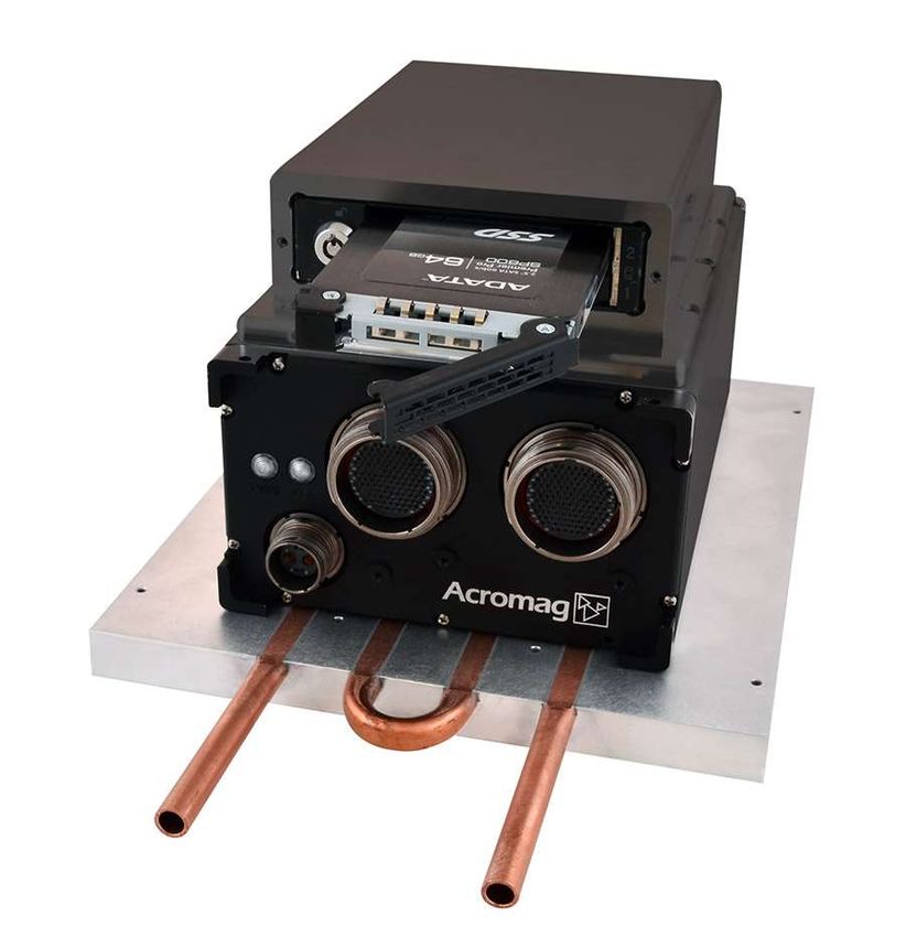
I. Introduction
Customers have started to move away from the
traditional rackbased system (VME and cPCI) or
deployed applications and are looking for a modern
alternative. VPX is one approach, but for many
applications the capabilities of VPX are overkill or
just too expensive. Small Form Factor (SFF) boxes
are becoming an attractive alternative but quite
often lack the processing power, flexibility and
standardization that customers are used to seeing in
their old rackbased systems.
A new breed of SFF products are now coming to market that offer processing power, expandability,
and even customization that customers were used to with their older systems, but at a fraction of
the cost. These new SFF products are able to pull together a broad range of industry standards to
meet the needs of military and industrial customers. By combining COM Express for the CPU,
PMC/XMC slots for specialized expansion such as FPGAs and Frame Grabbers, and mini PCI Express
slots for lower cost I/O, these new SFF products offer customers the processing power, flexibility
and standardization they need for their deployed application.
II. Design it be Rugged
SFF boxes have to be designed from the ground up to meet the needs of deployed military system.
This requires that the package is designed to manage heat, shock and vibration and EMI all while
maintaining a small package size. Once the design is complete, extensive testing will be required to
prove that the design meets the needs of the customer.
A critical element to this is thermal design. Heat within the box must be captured and rapidly
transferred to the exterior surface. From there it can be removed by either conduction or
convection cooling. Modern processor and PMC/XMC modules generate a lot of heat that if not
controlled, can rapidly cause systems to throttle back and even shut down. The use of internal
structures such as heat spreaders and conduction cooling rails are essential to a properly
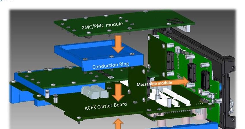
functioning design. In the image below (Figure 1), you can see how the CPU is designed with a heat
spreader that connects to the bottom of the chassis, thus capturing the heat from the CPU and
transferring it directly to the housing. This prevents the heat from the CPU travelling upward into
the carrier and expansion slots. This is also true for the placement of the expansion modules
(PMC/XMC and mini PCIe/mSATA modules). By placing them on heat conduction rails that make
contact with the carrier, their heat can be routed to the outside without causing additional heat
buildup around the CPU.
Tel: 2482950880 Fax: 2486241541 solutions@acromag.com www.acromag.com
2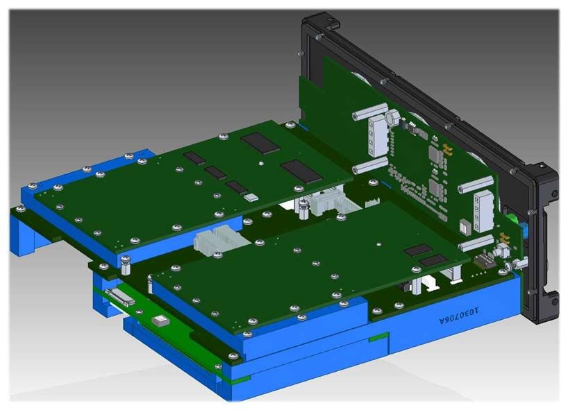
Figure 1
The conductioncooling rails and heat spreaders not only conduct the heat to the external structure
of the box, but are essential in providing additional stiffening of the enclosure needed to meet
rigorous shock and vibration requirements of the customer. Having the CPU heatspreader and
conductioncooling rails mounted directly to the outer box (Figure 2) also prevents resonant
frequencies from being created on the carrier, reducing failures from being caused over time in high
shock and vibration environments.
Figure 2 – Side view of CPU with conduction cooling and front panel.
Tel: 2482950880 Fax: 2486241541 solutions@acromag.com www.acromag.com
3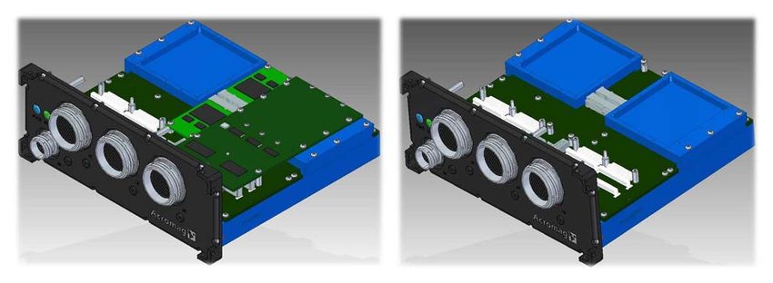
For additional thermal control, CPU Power Management
provides programmable power limits. This allows the user
to “dialdown” the maximum power consumption of the CPU
in applications where heat and/or power is a concern. For
additional heat management, mounting the unit to a cooling
plate (Figure 3) will help keep high temperatures under
control.
Building it “Rugged” means designing the system to
accommodate all expected needs. This includes a power supply capable of Figure3 – cooling plate
meeting all expected expansion needs. Additional PMC/XMC and mini
PCIe/mSATA modules as well as special defense industry power requirements such as MILSTD704
and MILSTD1275 should also be taken under consideration.
III. Design it be Powerful!
Most defense customers seek a balance between more processing power while still meeting the
SWAP (size, weight and power) budget available for their application. Where budget (power and
price) allows, Intel’s i7 is an ideal processor for the job. However, not all application need this
much processing power nor the wattage required (TDP of 47 watts). As mentioned earlier, the Intel
i7 CPU allows programming a lower power limit in the BIOS setup. This allow the designer of the
SFF system to accommodate either requirement with a single component, adjusted to best fit the
application’s needs. In addition, the CPU should not only be the latest generation but should be
listed on Intel’s Embedded Roadmap (http://ark.intel.com) to insure longevity of design.
IV. Make it Expandable!
One of the key advantages of rack based systems has been their expansion capability to meet the
needs of the application. This historically was done by adding specialized I/O boards on the
backplane. In recent years, with the availability of smaller electronic packaging, using PMC/XMC
modules for expansion has become the norm. The key advantage PMC/XMC modules offer is that
they are based on wellestablished standards and provide a wide variety of functionality from
multiple vendors. These include user programmable FPGA, graphics processors/frame grabbers,
analog and digital I/O and a wide range of specialized communication modules. PMC/XMC modules
have one other key advantage – they are often offered in a conductioncooled design.
But great care must be taken in adding PMC/XMC modules within the SFF packages. Questions to
be asked include:
1. Is there sufficient power available in the design to support the required PMC/XMC module(s)?
How much powered is allocated to each slot?
2. How will the added heat be accommodated? Is there appropriate conduction cooling to meet
the needs of the modules.
3. How is the I/O from the PMC/XMC modules accommodated? Are special cables and connectors
required or has the designer provided a means of routing the I/O signals to the front panel
connectors?
Tel: 2482950880 Fax: 2486241541 solutions@acromag.com www.acromag.com
4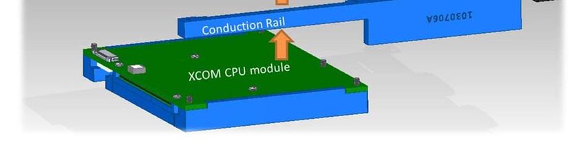
Figure 5 – ARCX with PMC and Mini PCIe card installed Figure 6 – ARCX internal electrics with conduction cooling
and front panel metal work.
Since a welldesigned SFF system should readily allow PMC/XMC module(s) to be added without
changes to the design, the power supply must have the appropriate overhead from the start.
Conduction cooling and I/O connections from J4/J16 should also be included in the base design
without requiring modification by the user (Figure 6).
While PMC/XMC modules are designed to do the “heavy I/O lifting a second industry standard is
starting to show up in SFF system designs. Mini PCI Express (Figure 5) was designed by the PCISIG
standards group for implementation in laptop computers. Its small package size (30 x 50.95mm)
and low power requirements are well suited for the SFF system. Although not capable of being
used for complex function such as programmable FPGAs or frame grabbers, they are well suited for
adding devices such as WiFi or SSD (up to 256GB) memory to the system.
V. Make it customizable
One of the short comings of any SFF system that is designed to be conduction cooled is the ability to
create custom I/O interfaces. In an air cooled open rack system, Rear Transition Modules (RTMs)
can easily be added in the form of a daughter board (for example, Acromag’s AXM modules for their
FPGA boards). Acromag addresses this need with a User/Factory customizable module or custom
mezzanine module extensions (Figure 7). These custom mezzanine modules electrically sit in the
path between the PMC/XMC module’s rear I/O (J4/J16) and the I/O connector on the front of the
SFF box.
Tel: 2482950880 Fax: 2486241541 solutions@acromag.com www.acromag.com
5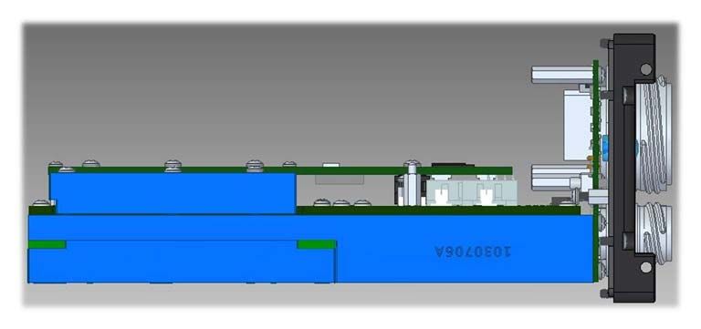
These mezzanine modules also allow customers to create special interfaces needed for specific
applications. Examples of how these modules can be used include:
x RS424/Clock interface to a user programmable FPGA – The customer had a mix of LVDS and
RS424 signals that they need to interfaced to a FPGA. The FPGA supported LVDS but not
RS424 via rear I/O. In addition, they had to intercept and reamplify a common clock signal
used by the FPGA. A custom mezzanine module was created specifically for these
requirements.
x Cable Equalizer Circuit – The customer needed to install an XMCbased Frame Grabber. The
module required external magnetics and a cable equalizer circuit for each of the connected
channels. All of these functions were designed on to the custom mezzanine modules.
x Internal cabling to accommodate MilStd1553 The customer installed a mini PCI Express
card with MilStd1553 and a GPSbased clock pulse. The design required the use of internal
cable but the customer wanted to route these signals through the available D38999 I/O
connectors. A custom module was designed that the added mating connector on the custom
mezzanine modules that then routed the signals to unused pins on the D38999.
x GPS antenna cabling – Not all custom features require mezzanine modules. Customers with
special cabling and connector needs can be accommodated with only slight modification of
the front housing. The Acromag ARCX front panel electronics is designed with notches to
allow cabling and connectors to access the front panel metal work without alteration.
Figure 2 – Internal ARCX electronics showing the location of custom mezzanine modules with standoffs
Tel: 2482950880 Fax: 2486241541 solutions@acromag.com www.acromag.com
6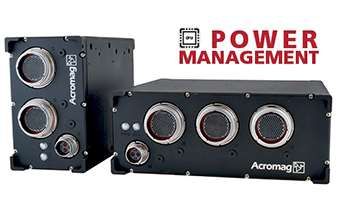
VI. Conclusion
The new breed of Small Form Factor systems now offer the processing power, expandability and
customization that were available in older rackbased systems. These new SFF designs incorporate
a broad range of industry standards to meet the needs of military and industrial customers.
Combining COM Express, PMC/XMC and mini PCI Express offers customers the processing power
and flexibility in a “standardized” package well suited for deployed applications.
About Acromag
It is an AS9100 and ISO 9001certified international corporation with a world headquarters near
Detroit, Michigan and a global network of sales representatives and distributors. Acromag offers a
complete line of embedded computing and I/O solutions including bus boards, singleboard
computers, FPGA modules, embedded computers, COM Express, mezzanine modules, wiring
accessories, and software. Industries served include military, aerospace, manufacturing,
transportation, utilities, and scientific research laboratories.
For more information about Acromag products, call the Inside Sales Department at (248) 2950310,
Fax (248) 6249234. Email solutions@acromag.com or write Acromag at 30765 South Wixom
Road, Wixom, MI 483932417 USA. The web site is www.acromag.com.
Tel: 2482950880 Fax: 2486241541 solutions@acromag.com www.acromag.com
7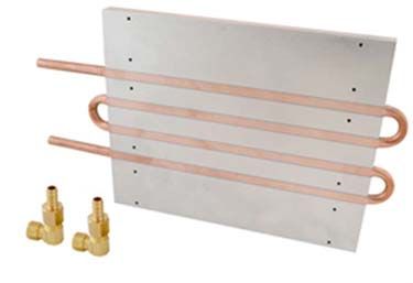
You can also read