Company Members: Vortex Brainnovates Technical Report 2019 - Alexandria, Egypt
←
→
Page content transcription
If your browser does not render page correctly, please read the page content below
Vortex Brainnovates
Technical
 I.
          Report 2019

Alexandria, Egypt

Company Members:

         Mentors

      Ziad Abdelkerim
       Asmaa Bahaa
     Abdulaziz yousry
    Mrawan Ahmed taha

                        Page 1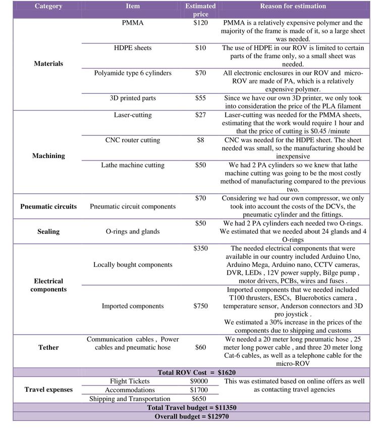
I- Abstract
In response to the Eastman’s request for a Remotely Operated underwater Vehicle (ROV) which can carry out
many tasks in different conditions, Vortex Brainnovates has designed and built the ROV, Octopus, to ensure the
public safety, maintaining healthy water ways and preserving history. Octopus was tested to make sure of
maximum mission success.
Vortex Brainnovates was founded this year, by the mentoring of Vortex Company, aiming to come out with the
best quality ROV. The team consists of 10 enthusiastic and determined middle and high school students who spent
months of learning, planning, developing, testing and troubleshooting that eventually resulted in our ROV,
Octopus, as a marketable product.
Octopus is characterized by its light weight, small size, stability, easy assembly and low cost. It was manufactured
using various techniques such as laser-cutting, CNC routing and 3D printing. Octopus is equipped with four
BlueRobotics T100 Thrusters for the necessary movements, a pneumatic system for the main gripper, cameras for
vision, custom-made printed circuit boards and sensors including a temperature sensor and a leakage detection
sensor. The ROV is also equipped with a micro-ROV for inspecting pipes. The team is confident that Octopus is the
most suitable ROV to fulfill the laboratory’s request.The following information show how Octopus was built to
perform the required missions.
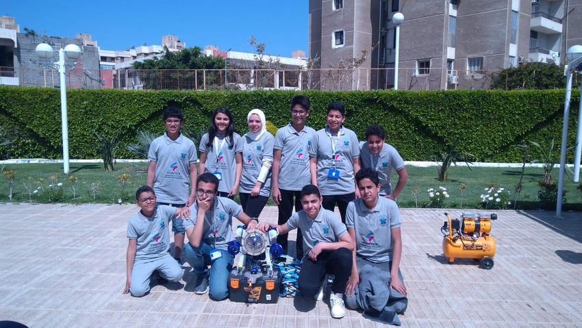
Figure 1: Vortex Brainnovates Team in Regional Competition
Page 2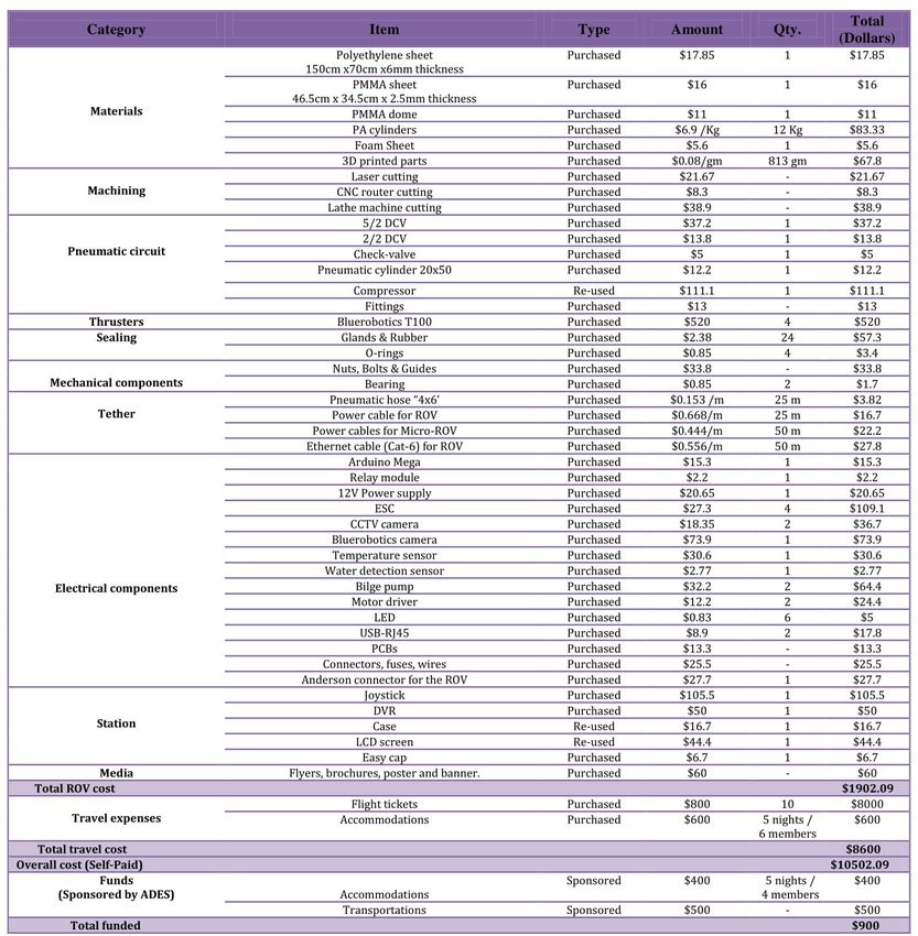
Table of Contents
I- Abstract ................................................................................................................................................................ 2
II-   Design Rationale .............................................................................................................................................. 4
       A- Design Process ........................................................................................................................................... 4
       B- Design constraints ...................................................................................................................................... 4
       C- Mechanical Design .................................................................................................................................... 4
                  1-Frame: ........................................................................................................................................... 4
                  2- Buoyancy and stability................................................................................................................. 5
                  3- Propulsion: ................................................................................................................................... 5
                  4- Electrical enclosure and sealing:.................................................................................................. 6
       D- Electrical Design........................................................................................................................................ 7
                  1- Power Distribution ....................................................................................................................... 7
                  3-Control system: ............................................................................................................................. 8
                  4- Tether(fig 24). .............................................................................................................................. 9
                  5- Vision system............................................................................................................................. 10
                  6- Station ........................................................................................................................................ 10
       E- Software ................................................................................................................................................... 11
                  1-Onboard Software ....................................................................................................................... 11
                  2-Top-Side software ....................................................................................................................... 11
                  3- Mission specified software: ....................................................................................................... 11
       F- Mission specified tools and payloads ....................................................................................................... 12
III- Safety ............................................................................................................................................................. 14
       A- Safety philosophy .................................................................................................................................... 14
       B- Safety instructions.................................................................................................................................... 15
       C- ROV safety features: ................................................................................................................................ 15
IV- Logistics ......................................................................................................................................................... 16
       A-Company Organization and Teamwork………………………………………………………………….16
       B-Project management……………………………………………………………………………………...16
V-    Conclusion ..................................................................................................................................................... 18
       A-Challenges ................................................................................................................................................ 18
       B- Testing and Troubleshooting ................................................................................................................... 18
       C-Lessons learned and skills gained ............................................................................................................. 18
       D-Future improvements ................................................................................................................................ 18
       E- Reflections ............................................................................................................................................... 19
VI- Acknowledgments ............................................................................................................................................. 19
VII- References ........................................................................................................................................................ 20
VIII- Appendices ...................................................................................................................................................... 21
       Appendix A: System interconnection diagrams............................................................................................ 21
                  1- Electrical SID of ROV and Micro-ROV .................................................................................... 21
                  2- Pneumatic SID of ROV ............................................................................................................. 21
       Appendix B: Flowcharts ............................................................................................................................... 22
       Appendix C: Safety Checklist....................................................................................................................... 23
       Appendix D: Total Project Cost .................................................................................................................... 24

                                                                             Page 3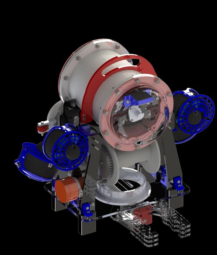
II- Design Rationale
A- Design Process
The design of Octopus is a result of a lot of hard work of
our team. We tried to make a superb design with the
least cost possible. We changed the design several times
till we reached this design. The team members discussed
the designs they had in their minds first. Then after
choosing one, the members of the electric team started
exploring what electrical components are needed in the
enclosure. After that, we used SolidWorks for the design
of Octopus so we can manufacture it easily afterwards.
                                                                       Figure 2: Octopus the ROV and its fee hand Sketch
B- Design constraints
A set of strict constraints had to be followed while designing Octopus. These constraints included weight and size
limits; the vehicle and its tether combined are to fit in a 60 cm diameter ring and weigh no more than 15 Kg in air.
The design team made sure that Octopus met these requirements. Octopus and its tether weigh 11 Kg combined,
and fits into no more than a 600 mm diameter ring(fig 3).

                                         Figure 3: Dimension Fitting of Octopus

C- Mechanical Design
1- Frame:
 The base of the ROV is made of a 6mm-thick laser-cut transparent poly methyl
 methacrylate (PMMA) sheet to provide a clear view beneath the ROV for the
 pilot. PMMA was also selected due to its high density (1180 Kg/m3) to shift
 the center of gravity downwards, to achieve more stability. The slots in the
 base are used to correctly mount all the components in their supposed places.
 The webs carry the weight of the electrical enclosure, connect all the parts
 and hold the thrusters in place. They are made of 6mm-thick high density
 polyethylene as it has high impact strength and high fatigue resistance        Figure 4: Octopus’s Frame
 compared to other polymers. There are 4 supports; 3 for the electrical
 enclosure to be seated on them and 1 from the top to lock the electrical enclosure into place. They also have
 guides to prevent the enclosure from rotating or sliding. They were manufactured using a CNC (computerized
 numerical control) router.

                                                         Page 4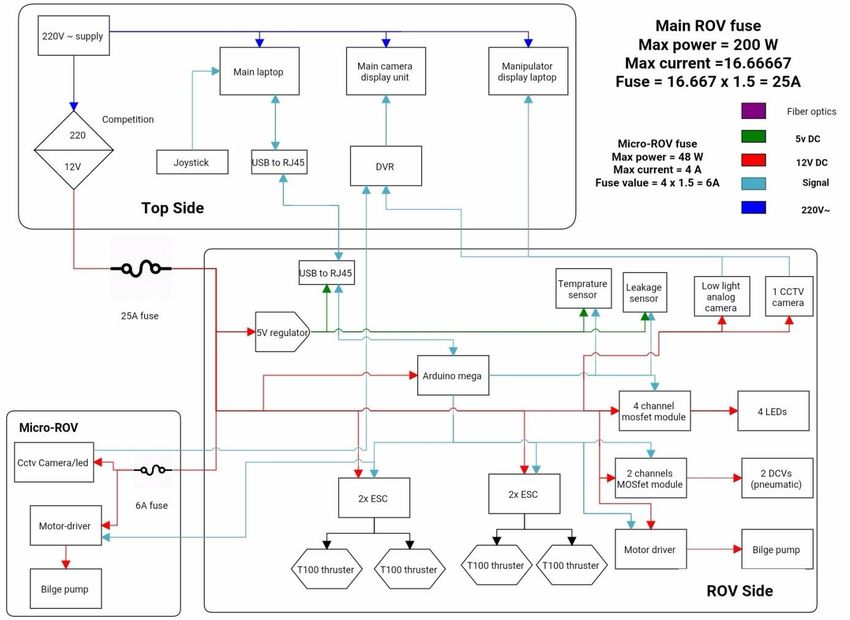
3D printed L and U-shaped parts made of Polylactic
    acid (PLA) are used for fixation; to attach the webs
    to the base (fig 5), where the webs fit into slots in the
    base and then fixed to the base using M4 bolts. The
    thrusters are attached to the U-shaped parts (fig 6)
    then mounted on the webs. The 3D printed parts
    have a filling of 100% to be able withstand the
    stresses applied to them.
                                                                Figure 5: L-Shaped3D printed      Figure 6: U-Shaped3D printed
                                                                             parts                             parts

                                 The front face of the ROV Octopus has a 6mm thick transparent poly methyl
                                 methacrylate (PMMA) dome(fig 7). The dome serves multiple purposes as providing the
                                 cameras with a clear vision of the surrounding, adding more space to afford two cameras
                                 at different view angles and reducing the overall drag force on the ROV which gives
                                 more efficient thrust power usage. The flow over the ROV was simulated to determine
                                 its coefficient of drag.

Figure 7: Octopus’s Front Face

  2- Buoyancy and stability
  The largest displacement component is the
  electronics enclosure, occupying a displaced
  volume of 5663.76 cubic centimeters; hence,
  why it's placed at the top; shifting the center
  of buoyancy upwards. The weights and the
  heavy payloads are placed at bottom shifting
  the center of weight downwards to achieve
  stability. The restoring moment provides the                           Figure 8: Centers of Buoyancy and Gravity
  stability needed during maneuvering

  3- Propulsion:

  Our aim was to use the least number of thrusters possible in Octopus
  without losing any of the degrees of freedom needed for maneuvering. A
  four thruster configuration(fig 9) was chosen to reduce power consumption
  and the overall cost of the ROV. Four T-100 Blue Robotics thrusters were
  used to drive ROV Octopus.                                                                        Figure 9: Octopus’s four
                                                                                                      thruster configuration

  This four-thruster arrangement allows the vehicle to move straight sideways, a motion called “Crabwalk” in
  addition to many other movements ,but does so without requiring any thrusters to occupy a central position in the
  vehicle. It relies on thrust vector addition to produce vertical and crabwalk motions.
  The vectored thrusters interact to produce a wide range of vehicle motions. When both of the vectored thrusters
  are generating a force diagonally upward and towards the midline, represented by the blue arrows, these thrust
  vectors are equivalent to the combination of a vertical force, red arrows, and a horizontal force, black arrows.

                                                                Page 5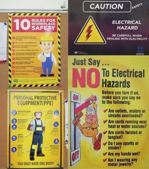
The resultant force is directed upwards and propels
  the vehicle towards the surface. And if both of these
  thrusters now reverse their direction, the vehicle will
  dive. Thus, this arrangement allows straight up and
  straight down motion(fig 10).

                                                                            Figure 10: Octopus's Vertical Movement

                                                                  The port thruster is creating a propulsive force downward
                                                                  and to the left, while the starboard thruster is creating a
                                                                  force directed upward and to the left. In this case, the
                                                                  horizontal, red, components cooperate, so the vehicle is
                                                                  pushed sideways in a crabwalk motion to the left. And if
                                                                  both of these thrusters reverse their directions, the
                                                                  horizontal, red arrows, will cooperate in the opposite
                Figure 11: Octopus's Lateral Motion
                                                                  direction and the vehicle will crabwalk to the right(fig 11).

  4- Electrical enclosure and sealing:
  At the heart of our vehicle, is an inclusive lathed machined
  pressure housing that is made of polyamide (PA nylon 6) with an
  integrated flange(fig 12). This housing contains the electronics
  structure and its endings are closely sealed by transparent
  PMMA faces: one of them has one 3.5 mm radial groove and 1.9
  mm depth that houses O-rings of Buna-N/NBR rubber which are
  responsible for the sealing between the housing itself and the
  acrylic face

                                                                                         Figure 12: Electrical Enclosure

                                                    Moreover, we chose the housing cylinder structure to be made of (PA
                                                    nylon 6) because of its excellent surface finish, stiffness, strength,
                                                    manufacturability and lightweight.

Figure 13: Stress analysis of the Electronic Enclosure

  The electrical enclosure internal structure(fig 14) consists of PMMA
  shelves holding the electronic components and pneumatic system, while
  the main and secondary cameras are held on 3D printed holders inside
  the dome. LEDs are fixed on PMMA parts rather than 3D printed parts
  because PMMA has a higher melting point. The entire structure is pulled
  out of the cylinder whenever modifications need to be done.

                                                                                        Figure 14: Internal Structure for the
                                                                                        electrical and electronic components

                                                                 Page 6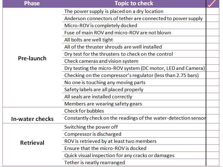
Moreover, for complete sealing of the electrical enclosure, Agro cable glands
(Nickel-plated brass ) (fig 15) were used to seal between the cables and the
cable holes . Some modifications were made on the gland; custom made
rubber fittings were made in order to match the diameter of the cables going
into and out of the electrical enclosure. For high modularity, the rear cover
which contains the grooves for the cables is designed specifically for simple
fastening of the glands. We made sure that a wrench was to easily reach easily         Figure 15: Nickel-Plated
each gland so we can fasten or unfasten any independently.                               Brass Cable Glands

D- Electrical Design
The ROV’s electrical system was designed to be as compact as possible for easy maintenance and troubleshooting.
The vehicle has a system onboard using customized double layer PCB on which the microcontroller is mounted.
Our joystick -through serial communication- sends signals to the microcontroller which controls the actuators,
while the C# based GUI displays the readings of sensors, direction of maneuvering and speed level. The vehicle is
surface-powered by a 12-volts external power supply which is fed through a series RC (Resistor-Capacitor) circuit
to avoid sudden changes in voltage levels and subsequently prevent noise and signal fluctuations. 5-volts
regulators are used to supply the sensors

1- Power Distribution
The current supplied from the 12 volt power supply passes through a 25Amp fuse, then reaches the main
electronics enclosure where it is fed to the onboard system through a series RC circuit. When a large load current
is drawn, a sudden voltage drop occurs across the tether; hence, electromagnetic interference (EMI) and noise
cause the cameras to flicker due to the high rate of voltage change (dv/dt). For that reason, a capacitor of 4700 µF
and a resistor of 110 Ω are connected in series to filter out the noise. As per the rules, the ROV system that is
disconnected from the surface supply must stop functioning in less than 5 seconds. Our system meets those
requirements as shown by the calculations in figure 17.
The 12 volts are used to supply the cameras, DCVs, thrusters, LEDs, Arduino and bilge pumps, while a 7805 voltage
regulator supplies 5 volts to the sensors.
                                      Table 1: Maximum Power Consumption Calculation

     Component Voltage             Max          Max         Quantit      Total max           Total max current
                (Volts)           current      power          y        power (Watts)            (Amperes)
                                (Amperes)      (Watts)

         T100           12           10          120           4             480                       40
     Bilge pump         12            2           24           2              48                        4
       Camera           12           0.2         2.4           3             7.2                       0.6
         DCV            12          0.28         3.36          2             6.72                     0.56
         LED            12          0.84          10           4              40                      3.36

       Maximum power consumed = 581.92 watts                        Maximum current = 48.52 Amperes

Maximum power is never reached because of our software interlocking system which limits the speed of the
thrusters. (1720 µs PWM input to the ESC fig 16) , two thrusters at a time)

Therefore, the actual maximum power is 200 Watts, and the maximum current is 16.6 Amperes.

                                                         Page 7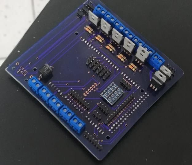
Figure 17: Discharge rate of capacitor               Figure 16: PWM Signal to the T100 thrusters

2-Communication:
USB to RJ45 (Ethernet) adapter (fig 18) is used, where the D+ and D- data lines
of the USB cable are directly connected to the TX and RX terminals of the
Ethernet cable. The Ethernet protocol is a full-duplex differential
communication based system. The USB extension enables us to control the
ROV from a considerable distance up to 50 meters away from the station.
The adapter offers an easy access to the Arduino directly to upload codes
without the need to open the electronics enclosure. Additionally, its cheap            Figure 18: RJ to USB converter
price and availability in local stores encouraged us to use it.

3-Control system:
                                         a- Microcontroller:
                                         Arduino boards were used because of their affordable prices and because
                                         they’re open source AVR microcontroller-based development boards which can
                                         be programmed easily. Specifically, Arduino MEGA (2560) 32-bit (fig 19) was used
                                         because it is relatively fast and has 54 digital input/output pins to be able to
                                         control all the ROV's actuators, and 12 analog input pins to be able to receive
                                         multiple sensor readings.
       Figure 19: Arduino Mega

b- Actuators control:
ESCs (Electronic Speed Controllers)
Using 4 ESCs (fig 20), the microcontroller is able to control the 4 thrusters using PWM
(Pulse width modulation).                                                                                Figure 20: ESC

                              “Monster” Motor Driver
                              The motor driver (fig 21) provides full speed and directional control to the DC motors/bilge
                              pumps used in the docking mechanism and the micro-ROV.

    Figure 21: Motor Driver

IRF640 MOSFETs
IRF640 MOSFETs are used for controlling the DCVs of the
pneumatic circuits and the LEDs. Conduction losses in the MOSFET
were calculated to ensure that its temperature rises to an accepted
level (fig 22).
                                                                                  Figure 22: MOSFET Calculation

                                                            Page 8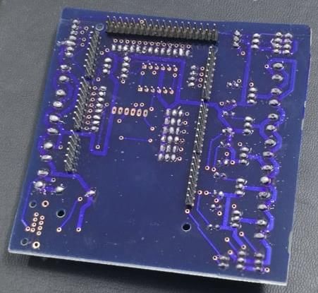
c- System onboard
During the design of our
customized double layer printed
circuit board (PCB) -which acts as
a motherboard (fig 23).- , we were
keen on making our board capable
of accepting additions and flexible
in use as possible; hence, it has
places to mount our commonly
used components e.g. regulators,
ESCs, Arduino Mega, MOSFETs,
water sensor...etc , while in terms
of the capability of accepting
additions, we pinned out the                                     Figure 23: Mother Board
unused pins (like unused digital pins and communication pins) to be used whenever needed. We also made our
analog pins ready to accept new sensors at any time just by mounting it directly in place.
A diode rated at 6 amperes is placed to protect the system from reverse voltage.

The widths of the traces were calculated based on the relation:
 Where I is the current, k is a constant, ΔT is Temperature Rise, and A is the cross-sectional area of the trace. The
 trace width can then be calculated by rearranging this formula to determine the cross-sectional area that our
 desired current can safely pass through. Then, the width is calculated from the cross-sectional area for a chosen
 thickness:

Based on the formulas: PCB trace width for signals equals to 0.8 mm and for high current loads is equal to 2.5mm.

4- Tether(fig 24).
a- ROV tether:
Communication:
The signal is transmitted from the station to the ROV
through two Category6 Ethernet cables which have 8
cores each. One cable is for the USB –RJ45 adapter,
while the other is for the camera. CAT6 was used as it
can provide serial communication at a rate of 250
Kbps.
                                                                                   Figure 24: Tether Diagram

                                                         Power transmission:
                                                         Based on the AWG wire sizing chart, we decided to use a 6
                                                         AWG (4 mm diameter) power cable in order to minimize the
                                                         voltage-drop (7.5%) across the tether's terminals and
                                                         subsequently providing the system with a more stable voltage
                                                         (fig 25).

 Figure 25: Voltage drop index (VDI) and American wire
                gauge (AWG) calculations

                                                              Page 9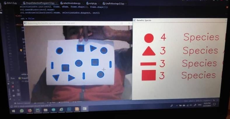
Pneumatic:
The pneumatic hose has an inner diameter of 4 mm and an outer diameter of 6 mm. It’s able to withstand
pressure up to 10 bars (106 Pa).
The tether of the ROV is 20 meters long and foam rods are attached to it with a constant spacing between them to
make the tether neutrally buoyant to minimize the drag on the vehicle and to keep it balanced.

 b-Micro-ROV tether:
The micro-ROV tether is a 12 pair telephone cable. 6 pairs for power transmission, 3 pairs for signal transmission for the
motor driver, 2 pairs for signal transmission for the camera and 1 pair signal transmission for the relay.

5- Vision system
a - Main camera:
An analogue CCTV camera having a focal length of 2.8mm, an angle view of
89.9° horizontally and 79.8° vertically is used. The camera was horizontally
oriented such that it gives the pilot a perfect view ahead of the ROV.

b- Secondary camera:
Another low light analogue Blue robotics camera with focal length of 2.1 mm
and an angle of view 128° horizontally and 96° vertically is tilted at angle of 50°
to have of the manipulator. It’s also used for image processing during the
identification of the benthic species beneath the rock.
                                                                                         Figure 26: Vision Cameras
6- Station
a- Main laptop:
Displays the readings needed by the pilot
while controlling the ROV through a
graphical user interface.
b- Secondary laptop:
Provides the co-pilot with all the mission
specified software needed during the
product demonstration such as length
measurement and image processing.
c- Manipulators control laptop:
Displays the video captured by the
manipulators camera.

                                                         Figure 27: ROV controls using Logitech 3D pro joystick

                                       d- Control panel:
                                       Our control panel fig(28) is built in a neat and workman like manner, without
                                       loose components or unsecured wires. A Logitech 3D Pro Joystick is used for
                                       controlling the ROV (fig 27). The DVR is used to display all the videos on the
                                       LCD BenQ screen to facilitate controlling the ROV for the pilot.

     Figure 28: Control Panel

                                                         Page 10
E- Software
1- Onboard Software
Our software engineers designed the onboard software using the most flexible architecture: the Round-Robin
architecture which is considered to be one of the simplest techniques; because there are no interrupts, no shared
data and no latency concerns. Our main loop checks each I/O devices in order, services any device requests and
returns data from the sensors to the top-side Arduino if needed. Therefore, our onboard software is characterized
by its ease of modification & debugging.
2- Top-Side software
Our Software Engineers implemented a fig(29). which
is C# based. The GUI receives data from the 3D Pro
Joystick which is then sent to the Arduino onboard
in the form of JSON (JavaScript Object Notation)
string. For the Arduino to process the received data,
it converts the data to JSON objects. Similarly, the
readings of the sensors received by the Arduino are
sent to the GUI by converting the data into JSON
strings.
Figure 29: Graphical User Interface
3- Mission specified software:
a-Measuring crack length and cannon dimensions
Using the CCTV camera placed on the base of the ROV, a photo is captured and
imported to the image processing software. A scale is set to a known distance in
the captured photo and using the concept of relative distance measuring based
on pixels counting, a relation between the number of pixels and the unit length
could be established which is used to determine the length of the crack during
dam inspection fig(30), as well as measuring all the dimensions of the canon to
calculate its volume.
Figure 30: Measuring the cracks
b-Calculating the canon’s volume and weight underwater
An Excel Sheet fig(31)is used to calculate the canon’s volume and weight underwater by inputting the canon’s
dimensions and its density.
Figure 31: Canon Underwater Weight Calculation
Page 11a- Determining the number and the type of the benthic species
The Algorithm used for detection of benthic species fig(32) is as
follows: When a frame is captured, it undergoes several
operations starting with grey scaling and thresholding, then
using the find contours function it detects all closed contours
and then check each of them, if the contour has 3 edges then it
would be a triangle and specified as species A, if it has 4 edges
then it’s either a square or a line, thus we check it’s aspect ratio
in order to determine whether it is a square which is species B
or a line which is species C, if the contour has more than 4
edges than it’s a circle and specified as species D. Figure 32: Benthic Species Identification
F- Mission specified tools and payloads
1- Manipulator
Octopus is equipped with a multifunctional, pneumatically
actuated, parallel jaw manipulator(fig 33).The manipulator is
used for holding objects throughout the missions.
The gripper motion is provided through the linear motion of the
pneumatic piston rod (bore 25 mm and stroke 50mm). It uses
the parallel link mechanism to convert the rod’s motion to the
gripping action. The jaws of the gripper are designed according
to the missions’ requirements, our design team designed each
part in the jaws carefully to enable the pilot to hold the mission
tools with ease. Figure 33: Octopus’s Manipulator
Jaws are manufactured from transparent acrylic (PMMA – Poly Meta Methyl Acrylate) so it won’t block the view
for the items gripped. The connecting links and the base of the piston are made from acrylic (PMMA – Poly Meta
Methyl Acrylate) to avoid high bending and 3 layers of jaws
The manipulator was designed to open up
to 10 cm to provide enough space for the
pilot to be able to pick up the objects
easily.
End effecter of the manipulator grooves
designed especially to suit all missions like
Trash rack, simulated rock and Reef/fish
balls.
Figure 34: Octopus Simulation of some missions using its Manipulator
b-
Page 122- Manipulator Attachments
Grout Tool:(fig 35)
A tool mounted on the main manipulator is designed to carry 300 ml worth of grout-
which is simulated by ½-inch to 1-inch Black Mexican Beach Pebbles- and then inserts it
into the void fig(37). This tool is also used to carry the trout fry.
Figure 35: The grout tool
Tire Tool: (fig 36)
This tool This tool is used to carry the degraded tires, which is simulated with 3-inch Corex drain pipe. It
is designed in way that encloses the tire by the two halves of the tool fig(39). The tool is also
attached to the main manipulator.
Figure 36: Tire Tool
Lift bag: (fig 38)
Our lift bag is made from a rubber balloon to which a hook and a pneumatic cable are
attached. This tool is used to lift the canon in mission 3. Once the hook is attached to
the U-bolt of the cannon, pressurized air pass through a non-return valve on the ROV to
inflate the lift bag.
Figure 38: Lift Bag
Figure 39: Octopus Lifting the Tire Figure 37: Octopus inserting grout
- 4- 3- Temperature sensor
For the temperature measurement we decided to use the temperature
sensor (DS18B20) for its sealed construction (IP68 0.6 bar), acceptable error
reading within 0.5 degree centigrade from the actual values and resolution
of 0.04 degree centigrade.
Figure 40: Temperature Sensor
Page 134- Micro ROV and Docking system
The micro ROV (fig 41) is designed to be as compact as possible; it
has only one bilge pump / sealed DC motor to provide its thrust, an
electrical enclosure made of PA type 6 , one camera and one LED.
The bilge pump is coupled with a T100 propeller through a stainless
steel coupling. Four plastic rollers are attached externally for a
smooth movement inside the Corex pipe.
Figure 41: Micro ROV
We designed a specific docking mechanism for micro ROV (fig 42)
where it releases a part of its tether while moving forward and wind
some while moving backwards. We used an external 2 spur gear
mechanism; these 2 gears serve as a speed reduction method with a
ratio of 4:1 to optimize the rotation of the propeller with the wire
and increase the torque. To maintain the Micro ROV locked in its
place, we designed a storage mode where some extrusions in the
micro-ROV fit inside slots in the main ROV.
Figure 42: Docking System
The micro-ROV is connected to the primary ROV through a 12 pair telephone cable. The Micro-ROV contains an
analogue CCTV camera, a motor driver to control the bilge pump and a relay module to control the LED.
III- Safety
A- Safety philosophy
Throughout the construction and operation of our ROV, safety has been
our highest priority. By employing safety protocols for using tools and
requiring adult oversight during meetings, we worked efficiently and
ensured the safety of our team members. All members were taught the
proper operation of each power tool before they began using them with
the supervision of one of our mentors. We are required to wear safety
goggles, gloves, masks, and close-toed shoes when working with power
tools. Also, to prevent accidents during fabrication, we cleaned all floors
and organized all surfaces after every meeting. While testing, running on
the pool deck was prohibited and all members (except the tether man)
worked away from the pool edge. In addition to safety precautions taken
during fabrication and testing, we developed many safety features
onboard our ROV to ensure the safety of vehicle operators.
Figure 43: Safety Precautions in our workshop
Page 14B- Safety instructions
During testing or manufacturing, at least two safety instructors must be
present at the workshop.
Using safety equipment as goggles, gloves and footwear while machining
or using pneumatic circuits is a must.
Members should make sure that their hands are dry when in contact
with the power supply.
When loading or unloading heavy components, slightly bend your body
forward to prevent back injury.
It's necessary to use a holder for the welding iron while soldering the
PCBs.
Use flux to clean the soldering iron after soldering.
A First aid kit, as well as a fire extinguisher, is provided in case of any
emergency.
C- ROV safety features: Figure 44: Safety instructions in our
Mechanical Safety Features: workshop
Our company prioritizes safety above all else, and believes that all accidents are preventable by
implementing strict safety measures. Therefore, numerous safety practices and protocols are enforced to
ensure that all members are working under a suitable and safe environment as Safety instructions are always
considered during designing, building, handling and testing of the ROV.
Our mechanical engineers ensured the presence of no sharp edges on the ROV. Also, moving parts, such as
thrusters, are covered with 3D-printed meshes designed by our mechanical team to meet IP20 standard.
Thus, protecting the thrusters from any foreign objects of 12.5 mm diameter or greater. Cap nuts are used to
eliminate any exposed threading.
Pneumatic Safety Features:
A pressure relief valve is added to the compressor and is set to 10 bars (106 Pa), which is the maximum allowable
pressure for the tank, and the pressure regulator is adjusted to 2 bars (2x10⁵Pa) at all times. Pneumatic fittings
either have O-rings, or Teflon tape is wrapped to prevent leakage. Also, all the pneumatic hoses are rated up to
10 bars (106 Pa) of pressure.
Electrical Safety Features:
A fuse-box between the 12V power supply and the tether, which has an inline two fuses of 25 Amp was installed.
Polarized connectors and color coded cables are usedto prevent inverted connections for power and signal
transmission across the whole system. ROV's static sealing was tested against a pressure up to 2 bars and
confirmed its potential for tolerance, and a water detection sensor is placed to detect any leakage . Glands work
as strain relief for electrical wires. The micro-ROV has a 6 amp fuse.
Warning Labels:
Warning labels are placed on thrusters and moving parts, high-pressure parts, PMMA parts that maybe subjected
to fractures, electrical components and close to the high brightness LEDs to insure that anyone in contact with
the ROV is fully aware of the possible hazards.
Page 15IV- Logistics
A- Company Organization and Teamwork
Vortex Brainnovates organization is mainly divided into two main divisions; electrical and mechanical, and each
division is subdivided into several project groups. Before starting the first stage of designing the ROV, elections
were held to select the board members including: a chief executive officer (CEO), electrical and mechanical chief
technical officers (CTO) and a chief financial officer (CFO).
The CFO set a clear budget and estimated the expenses to be paid within the manufacturing phase. The CEO held
general meeting to ensure that each division finishes the assigned tasks before the due date. The CTOs enabled
efficient work flow in each division, by setting weekly goals and breaking down the project into several smaller
points to be divided among the company members.
The mechanical division has 5 members: 2 responsible for CAD modeling 1 responsible for sealing and propulsion
system selection and 2 responsible for manufacturing. The electrical system has 5 members: 3 responsible for
the ROV’s software –including the GUI, the onboard system and image processing , 1 responsible for power and
tether calculations and 1 responsible for PCB design and manufacturing. The team also includes several non-
technical departments such as marketing, media and documentation.
B- Project management
A Work Breakdown Structure (WBS) is used to take the large project goal and break it down into a series of more
manageable tasks. These tasks are then prioritized; dependencies are linked, and then placed on a timeline. The
schedule is divided into five main phases: training, designing, manufacturing, testing and travel preparation.
During the training phase, all of members trained on SolidWorks software, Eagle PCB design software, pneumatic
systems, manufacturing techniques and communication systems.
After training, the company initiated the design phase, starting with the ROV’s core components –as the frame,
vision system, power distribution system and communication system- then moving to the mission specified tools.
Additionally, software members started in implementing the GUI and the image processing algorithms.
The next step is the building phase, where the company employees simultaneously manufacture the frame, tools,
and the PCBs. The testing phase consists of pilot practice and software calibration for the image processing, if an
unsatisfactory part is discovered during testing, parts will then be redesigned and manufactured. Finally,
company members prepare for travelling by flight booking and Visa preparations.
Figure 45: Project Timeline
Page 16C-Estimated budget
The following table shows the detailed estimation of the project’s budget and the reason for estimation of each
component used.
Table 2 : Estimated Budget
Page 17V- Conclusion
A-Challenges
1- Technical challenges
This was the first year that any of the company members implemented double layer PCB design. All members
had previous experience related to single layer PCB design, but when designing the mother board the tracks of
the PCB had to be traced on the upper and lower layers which was a real challenge
2- Non-Technical challenges
We don’t all live in the same city so managing our time was very difficult especially when we started
manufacturing and bringing the ROV all together. But we were able to assign tasks effectively and we divided
ourselves to teams that can meet easily in different parts of the country.
B- Testing and Troubleshooting
Each time we start our ROV, we follow the same steps every time. Before connecting the tether, we check if the
compressor’s regulator is at 2.5 bars. We check if the power supply is supplying 12 volts. After connecting the
tether, if the power is not working, we check the fuse and replace it if it failed. Then we start running the
thrusters and the gripper and make sure they are working correctly. If anything is wrong we check that all the
connections are in place correctly.
If a component is not working properly, we remove the component from the ROV, and test it to know the error.
C- Lessons learned and skills gained
1- Technical skills
Before building the ROV, our company members participated in a three-month training program which had all
the information we need to know to build the ROV. The courses taught us CAD design, sealing techniques ,
propulsion systems, manufacturing methods , materials and their properties, pneumatic circuits , PCBs , vision
systems, power distribution, communication and electronic control. We gained a lot of skills not only related to
ROVs but also skills needed in many other projects.
2- Non-technical skills
We gained a lot of non-technical experience related to marketing, since we attended various events were we had
to display our ROV. The competition taught us to think of ourselves as entrepreneurs , presenting an exquisite
engineering product.
D-Future improvements
ROV Simulation using Unity
Using Unity software, we were able to design an ROV
simulation software fig(46), where the missions are inserted
and the user can control the simulated ROV by joystick or
train with the VR with the highest degree of simulation
reality and water conditions.
Unity gives users the ability to create games in both 2D and
3D, and the engine offers a primary scripting API in C#, for
both the Unity editor in the form of plugins, and games
themselves, as well as drag and drop functionality. Our
objective is to help teams to compete training, without the Figure 46ROV Simulation on Unity
need to rent a swimming pool.
In the future, we aim to develop our game and make it available to students free of charge to market our ROV and the
possibilities that makes it stand out.
Page 18E- Refections
Youssef Taha (Mechanical Chief Technical Officer)
This has been an incredible journey and it’s one where I grew as a person and was able to
gain a lot of skills while also making new friends along the way and I am grateful to Vortex
Brainnovates for this great opportunity
Fareda Hossam
Undoubtedly, the road was full of Obstacles. I had a lot of passion to
learn how to build an ROV. I am happy to be a member of this team, they were helpful and
supportive.
VI- Acknowledgments
We would like to express our deepest appreciation and gratitude to
all those who provided us with the possibility to complete this
product and those who helped us overcome all the obstacles we
encountered along the way.
MATE Center – for organizing the international competition,
providing a platform for the growth of the community, and
promoting STEM education around the world.
AASTMT [Arab Academy for Science Technology & Maritime
Transport]– for organizing the local and regional competitions in
Egypt.
Hadath Company – for organizing the regional competition.
ADES [Advanced Energy Systems] – for sponsoring us by
providing us with accommodation during the competition.
Vortex Co. and Brainnovate Academy – for providing technical
courses and training as well as their continuous guidance and
mentorship.
Vortex Raiders and Vortex Troopers- for their technical support.
SolidWorks™ – for providing us with student licenses.
Our beloved family and friends- for their continuous support and
encouragement in all of our pursuits.
Page 19VII- References
Parker O-ring handbook. 50th Anniversary Edition
Fluid Mechanics Fundamentals and Applications by YunusCengel and John Cimbala 3rd edition
A. Arfaoui and G. Polidori, “Computational Fluid Dynamics Method for the Analysis of the Hydrodynamic Performance in Swimming
Mass Transfer - Advancement in Process Modelling, 2015.
The ROV Manual. A User Guide for Observations Class ROV/ Robert D. Christ. L. Wernli Sr. 2007,ISBN-97800750681483.
Blue Robotics T100 Thruster Documentation
Blue Robotics ESC Documentation
IRF640 MOSFET Datasheet
PLA Material Properties
Arduino, Logitech 3D Pro Extreme Joystick interface
MATE FORUM HUB
MATE ROV Competition Manual Ranger 2019
AWG wire sizing chart
Page 20VIII- Appendices
Appendix A: System interconnection diagrams
1- Electrical SID of ROV and Micro-ROV
2- Pneumatic SID of
ROV
Page 21Appendix B: Flowcharts
1- Top-side software 2- Onboard software
Page 223- Image Processing
(Benthic Species)
Appendix C: Safety Checklist
Page 23Appendix D: Total Project Cost
Page 24You can also read