Comparison of Environmental Effects from Different Offshore Wind Turbine Foundations
←
→
Page content transcription
If your browser does not render page correctly, please read the page content below
OCS Study
                                      BOEM 2020-041

Comparison of Environmental Effects
from Different Offshore Wind Turbine
Foundations

U.S. Department of the Interior
Bureau of Ocean Energy Management
Office of Renewable Energy Programs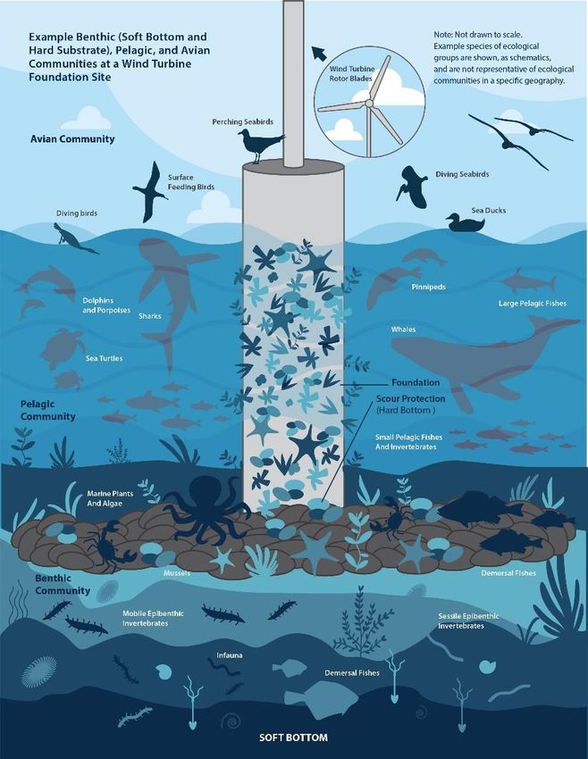
U.S. Department of the Interior
Bureau of Ocean Energy Management
Office of Renewable Energy Programs
OCS Study
                                                                  BOEM 2020-041

Comparison of Environmental Effects
from Different Offshore Wind Turbine
Foundations

August 2020
Authors:
Sarah Horwath, Jason Hassrick, Ralph Grismala, Elizabeth Diller

Prepared under Contract 140M0118A0004
By
ICF Incorporated, L.L.C.
9300 Lee Highway
Fairfax, VA 22031 USA

U.S. Department of the Interior
Bureau of Ocean Energy Management
Office of Renewable Energy Programs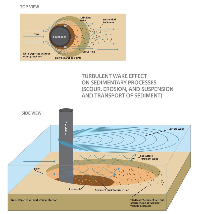
DISCLAIMER
Study concept, oversight, and funding were provided by the U.S. Department of the Interior, Bureau of
Ocean Energy Management (BOEM), Environmental Studies Program, Washington, D.C., under
Contract Number 140M0118A0004, BPA Call Order Number 140M0120F0017. This report has been
technically reviewed by BOEM, and it has been approved for publication. The views and conclusions
contained in this document are those of the authors and should not be interpreted as representing the
opinions or policies of the U.S. Government, nor does mention of trade names or commercial products
constitute endorsement or recommendation for use.

                                  REPORT AVAILABILITY
To download a PDF file of this report, go to the U.S. Department of the Interior, Bureau of Ocean
Energy Management website at www.boem.gov/Environmental-Studies-EnvData/, click on the link for
the Environmental Studies Program Information System (ESPIS), and search for 2020-041.

                                            CITATION
ICF. 2020. Comparison of Environmental Effects from Different Offshore Wind Turbine Foundations.
U.S. Dept. of the Interior, Bureau of Ocean Energy Management, Headquarters, Sterling, VA. OCS
Study BOEM 2020-041. 42 pp.

                                     ABOUT THE COVER
Cover graphic created by ICF.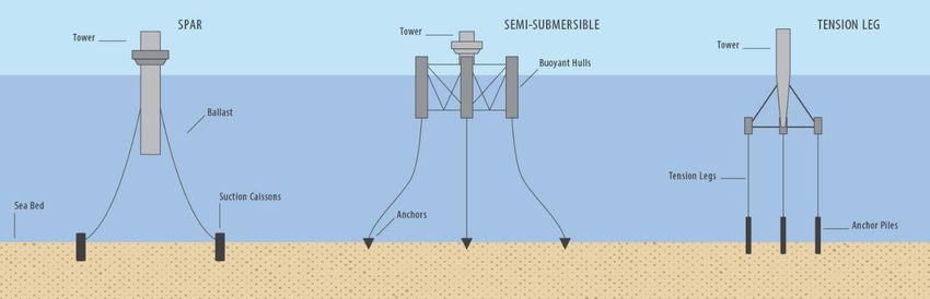
Executive Summary
The development of the offshore wind industry along the Atlantic coast of the United States has raised
concern from the public and throughout New England and the mid-Atlantic, about the potential effects
of offshore wind foundations on the marine environment. This white paper provides a summary of
currently available science that addresses potential effects of offshore wind foundations on the marine
environment and provides a comparison of different foundation types. This summary has been
developed to provide information to stakeholders who are concerned about the effect of foundations on
marine resources and to explain which foundations are suitable to use under certain conditions.
Public concerns revolving around the potential effects of foundations in the marine environment
associated with offshore wind development include:
    •   Differing degrees of impact depending on the foundation type.
    •   Direct effects on species from disturbance and/or loss of habitat during installation and operation.
    •   Alterations of physical processes, such as changes in hydrodynamics (i.e., the movement patterns
        of water, such as currents) and water quality (i.e., water chemistry, nutrient, and suspended
        sediment characteristics) that can result in changes in habitat suitability and indirect effects on
        species.
Some stakeholders recognize that offshore windfarm foundations and associated scour protection act
like artificial reefs by providing habitat that supports marine life. The current state of knowledge on this
topic is summarized below.

Types of Foundations
The offshore wind industry has adopted many of the foundation types that have proven successful in the
oil and gas industry. Prototypes and early projects used simple caissons (monopiles), small steel truss
jackets, and gravity structures in water depths less than 15 meters (m) (50 feet (ft)). As turbine locations
moved into waters up to about 40 m (131 ft) deep, larger steel monopiles dominated. From 40 m to 60 m
(131 ft to 197 ft) water depths, monopiles were joined by various space frame configurations (i.e.,
jackets, tripods, and tri-piles) as options for development. Beyond about the 60 m (197 ft) water depth,
offshore wind projects are expected to transition from fixed-bottom structures to floating structures.
Several floating offshore wind projects for deep water have now been deployed or are in advanced
planning stages.
Monopiles and tri-piles are driven into the seabed and are not well-suited for geological conditions with
shallow bedrock, boulders, or coarse gravel layers. Jackets, tripods, and some anchors for floating
foundations require soil conditions in which piles or suction caissons can be embedded, but they can
tolerate some obstructions better than monopiles. Gravity foundations and dead-weight anchors for
floating foundations sit directly on the seabed and can therefore be located where foundation penetration
into the seabed is not practical (Hammar et al. 2008). Table ES-1 summarizes the water depths and
geological conditions suitable for various foundation types.
Wind turbine spacing is not dependent on the type of foundation selected. Regardless of the type of
foundation, the cumulative areas of the wind turbine foundation footprints, including any scour
protection, typically cover less than 1 percent of the area of an offshore wind project over which wind
turbines are deployed (English et al. 2017). However, during installation of some foundation types, a
much larger area may be disturbed. For example, dredging for foundation pits of gravity foundations
can disturb up to 7 percent of the overall windfarm site area (Peire et al. 2009).

                                                    ES-1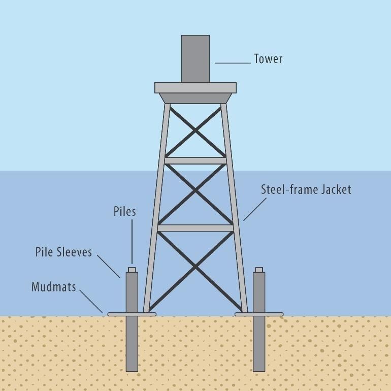
Table ES-1: Site Conditions and Foundation Selection
Maximum
Foundation Type Water Depths Geological Conditions
Monopiles 50 m (160 ft) - Sands and clays preferred.
- Not suitable for shallow bedrock or strata with boulders, cobbles, or coarse
gravel.
Jackets 60 m (200 ft) With piles:
- Stiff clays and medium to dense sands preferred.
- Possible in softer silts and clay, and in very soft sediments overlying stiffer
soils or bedrock.
- Less well suited for locations with many boulders.
With suction caissons:
- Medium stiff clays and fine to medium sand preferred.
- Not suitable for strata with cobbles, boulders, or coarse gravel layers or in
very soft soils.
Tripods 50 m (160 ft) - Same as jackets.
Tri-Piles 40 m (130 ft) - Sands and clays preferred.
- Not suitable for shallow bedrock or strata with boulders, cobbles, or coarse
gravel.
Jack-Up 100 m (330 ft) - Hard bottom conditions, stiff clays, and medium-to-dense sands preferred.
- Possible in softer silts and clay, and in very soft sediments overlying stiffer
soils or bedrock.
Suction Buckets 30 m (100 ft) - Medium stiff clays and fine to medium sand preferred.
- Not suitable for strata with cobbles, boulders, or coarse gravel layers or in
very soft soils.
Gravity 30 m (100 ft) - Sand, medium to stiff clays, bedrock, and strata with cobbles, boulders, or
coarse gravel.
- May not be suitable for very soft soils or weak clays.
Floating 220 m - Medium stiff clays, fine to medium sands, coarse sands, and gravel.
(720 ft) - Less well suited for locations with many boulders.
Environmental Effects from Foundations
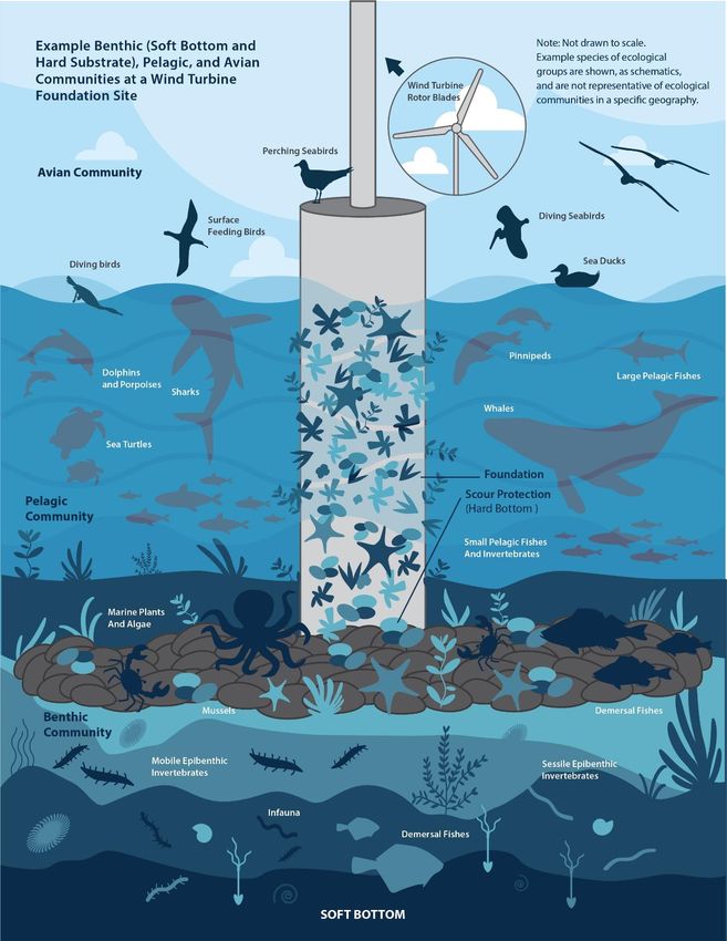
Ecological groups that were evaluated in this white paper and that could be affected by wind turbine
foundations are:
• Benthic (i.e. bottom-dwelling organisms) soft-bottom and hard-bottom communities
• Pelagic (i.e. residing in open water) community, including fishes, invertebrates, marine mammals,
and sea turtles
• Avian community, consisting of seabirds
Most changes to physical processes, including hydrodynamic processes (i.e., movement patterns of
water) and sedimentary processes (i.e., alterations to seabed substrates by natural forces), that can affect
species and habitats are localized and spatially limited, which means they occur in the vicinity of the
foundation, within boundaries of the offshore wind project, or within the down-current extent of wakes
generated by obstruction to prevailing currents. Most changes to physical processes are likely to occur
for the duration that the offshore wind foundations are in place. After operations cease, structures are
removed, although a scour pad around the footprint may remain if determined to be beneficial. Some
changes are more temporary in nature and only occur during installation activities.
Activities such as dredging for site preparation of gravity foundations, or reverse-circular drilling for
some monopiles, are expected to have greater seabed disturbance compared to methods that require low
levels of bottom disturbance, like deadweight-anchored floating foundations and suction bucket
ES-2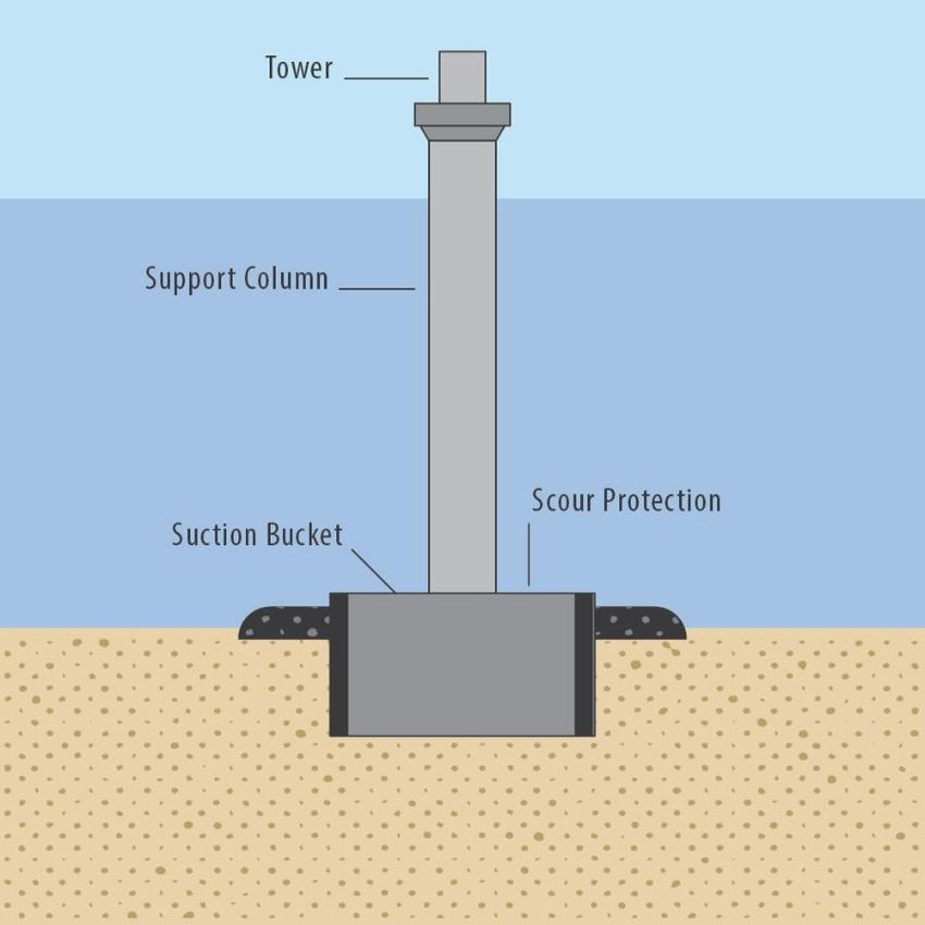
foundations. Similarly, foundations that have smaller footprints, like jacket and floating foundations, are
expected to result in relatively lower disturbances than structures with large footprints like gravity
foundations. However, because of the temporary nature of the effects during installation, the small area
directly affected by footprints in comparison to the overall offshore wind lease area, and possibility to
reposition foundations (i.e., micrositing) to avoid sensitive features such as complex habitat, effects on
benthic habitat are relatively minor overall. Additionally, baseline disturbance levels affecting benthic
habitats, like rearrangement of the seabed due to severe storms or changes in sedimentary processes due
to seasonal changes in ocean currents, may have relatively larger effects than foundation installations,
depending on site-specific conditions and geographical locations. Similarly, wake and scour effects may
vary across foundation types, but these effects are also localized and site-specific, and, given that any
windfarm would be sited at least 12 miles offshore, scour at sites in the U.S. would be limited compared
to windfarms sited in highly tidal zones, like in parts of Europe.
Beneficial effects from offshore wind project installation and operations include creating habitat
comparable to artificial reefs, with increased biodiversity, abundance, and biomass, as well as providing
enhanced foraging opportunities and refuge areas for many species of fishes, seabirds, sea turtles, and
marine mammals.
Larger offshore wind projects take a longer time to install, extending the time period for effects to occur
and increasing the risk of adverse interactions with sensitive ecological periods, such as spawning or
migration periods. However, cumulative effects on physical processes from multiple turbines or
adjacent wind projects are not expected to be perceptible because of wide spacing between individual
turbines (at least 500 m [1,640 ft] in most cases). Cumulative, regional-scale beneficial artificial reef
effects may occur when offshore wind projects are sited in proximity to each other, although such siting
would also increase the cumulative risk of invasive species range expansion due to the “steppingstone”
effect that could facilitate their spread across a region.

Conclusions
The type of offshore wind foundation utilized is highly dependent on the geological conditions and
water depths of the windfarm site. The environmental effects of offshore wind turbine foundations are
generally limited to the immediate vicinity of the foundations and the windfarm site area. The
magnitude of the effect may vary among foundation types primarily due to each type’s underwater
surface area, volume it occupies in the water column, and its footprint on the seabed.
Specific conclusions:
    •   Direct effects from the presence of the foundation structure on benthic species and habitats are
        typically greatest at monopile foundations and least at floating foundations. However, the effect
        across all foundation types is minimal, considering that typically less than 1 percent of the area of
        an offshore wind project site over which wind turbines are deployed is covered by structure
        footprints, including scour protection (English et al. 2017). However, seabed preparation for some
        gravity foundation designs may temporarily disturb areas up to a magnitude larger (i.e., less than
        approximately 7 percent of a windfarm site) (Peire et al. 2009).
    •   Foundations can act as artificial reef-like structures, which can have beneficial ecological effects.
        Compared to monopiles, these beneficial effects could be larger with a jacket foundation, given
        the much greater surface area associated with its lattice structure, and may be greater with some
        types of floating foundations depending on depth and surface area of the submerged structures.
    •   Risk of the spread of invasive species primarily varies with geographic location. For example,
        ocean current dynamics can influence transportation of invasive species to windfarm sites and
        presence of invasive species in the vicinity may increase the likelihood of spread to new
        structures. Risks are largest for gravity and floating foundations, compared to other foundation

                                                   ES-3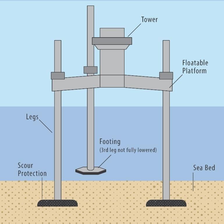
types, because they are generally towed to the site from ports, which increases the potential for
    the introduction of invasive species at the windfarm site.
•   Wake effects, which include hydrodynamic changes, for example increased concentration of prey
    in wakes and changes to larval recruitment dynamics, would be similar across most foundation
    types. Compared to monopiles, smaller wake effects would be expected at jacket foundations, due
    to relatively less structure volume in the water column, and near the seabed at floating
    foundations, due to weaker currents at greater depths. Larger scour effects would be expected at
    gravity and suction bucket foundations compared to monopiles, due to the wider diameter of the
    base of gravity foundations near the seabed.
•   Effects associated with the release of suspended sediment are mostly associated with installation
    activities. The smallest effects are expected for suction bucket foundations, which involve
    relatively little sediment disturbance during installation. The largest effects are expected for
    gravity foundations that require seabed preparation (e.g., dredging) and for monopiles if they use
    reverse circular drilling, both of which cause more extensive sediment disturbance than pile
    driving does during installation.
•   Some species seek out wind turbine foundations for resting areas or enhanced feeding
    opportunities. For migratory species, there is concern that introduction of foundations in the
    otherwise featureless offshore environment could alter species’ migration patterns by attracting
    them to linger at wind farm sites. This attraction effect is expected to be similar across foundation
    types, except for floating foundations, which have relatively less infrastructure extending through
    the entire water column.

•   For species sensitive to visual or spatial disturbances, avoidance effects may result in effective
    loss of utilized habitat within an offshore wind project site, but typically an abundance of
    available surrounding habitat exists. Like the attraction effect, this avoidance effect is expected to
    be similar across most foundation types, but likely would be smaller at floating foundations,
    which are installed in deep water and have relatively less volume of infrastructure extending
    through the entire water column.

•   Underwater noise and pressure waves, particularly those caused by foundation installation
    activities, may cause mortality or injury to fishes, marine mammals, and invertebrates. Behavioral
    alterations from acoustic effects, such as startling, fleeing or hiding, may occur during foundation
    installation activities, such as pile driving. Pile driving during installation of some monopile,
    jacket, tri-pile, tripod, carry acoustic effects that are anticipated to be relatively similar across
    foundation types. Floating foundations can be installed by pile driving, with a smaller anticipated
    impact associated with smaller piles. Other installation methods or activities, such as dredging for
    site preparation of gravity foundations, vibratory pile driving, and reverse-circulation drilling,
    also cause noise. However, those activities would likely emit less noise and pressure wave levels
    than pile driving. The least noise-emitting activities occur during installation of suction bucket
    foundations and floating foundations that use suction caissons, drag, dead-weight, or embedded
    anchors.

                                                ES-4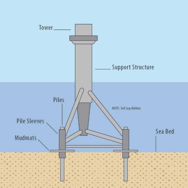
Contents
Executive Summary ..............................................................................................................ES-1
List of Figures ............................................................................................................................. ii
List of Tables .............................................................................................................................. ii
Abbreviations and Acronyms...................................................................................................... iii
1         Introduction ........................................................................................................................1
    1.1        Stakeholder Concerns ..................................................................................................1
    1.2        NEPA and the White Paper ..........................................................................................1
2         Types of Foundations .........................................................................................................2
    2.1        Monopile Foundations ..................................................................................................4
    2.2        Jacket Foundations ......................................................................................................6
    2.3        Tripod Foundations.......................................................................................................8
    2.4        Tri-pile Foundations ......................................................................................................9
    2.5        Jack-Up Foundations ..................................................................................................10
    2.6        Suction Bucket Foundations .......................................................................................12
    2.7        Gravity Foundations ...................................................................................................13
    2.8        Floating Foundations ..................................................................................................15
3         Environmental Effects from Foundations ..........................................................................17
    3.1        Introduction to Environmental Effects Evaluation and Approach .................................17
    3.2        Changes in Benthic Habitats.......................................................................................19
    3.3        Artificial Reef Effect ....................................................................................................19
    3.4        Invasive Species Spread ............................................................................................20
    3.5        Wake Effects and Scour .............................................................................................21
    3.6        Suspended Sediment and Sediment Deposition .........................................................24
    3.7        Release of Sediment Contaminants............................................................................25
    3.8        Attraction Effects ........................................................................................................26
    3.9        Avoidance Effects .......................................................................................................27
    3.10       Acoustic Effects ..........................................................................................................28
4         Summary and Conclusions...............................................................................................30
    4.1        Types of Foundations and Site Suitability ...................................................................30
    4.2        Ecological Effects Summary .......................................................................................31
    4.3        Conclusions ................................................................................................................35
5         Literature Cited .................................................................................................................37

                                                                        i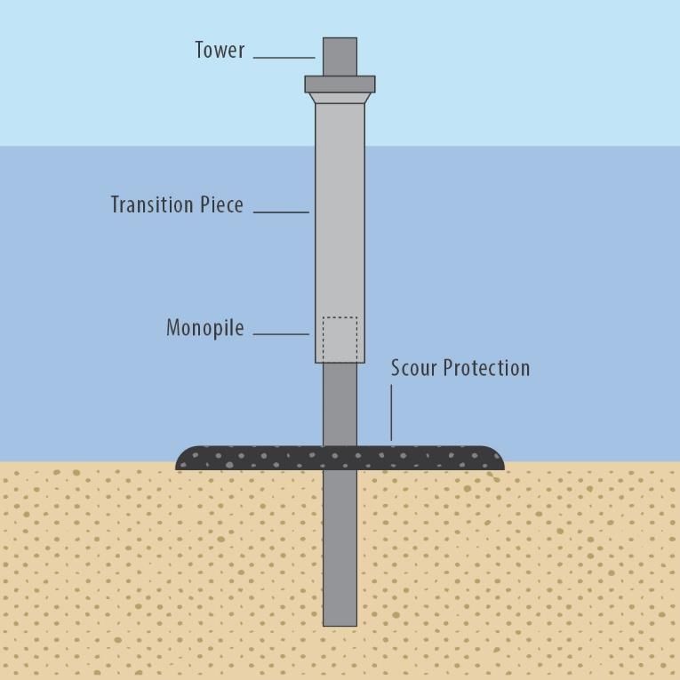
List of Figures
Figure 1: Offshore wind foundation types ................................................................................................. 3
Figure 2: Monopile foundation.................................................................................................................. 4
Figure 3: Jacket foundation...................................................................................................................... 6
Figure 4: Tripod foundation ...................................................................................................................... 8
Figure 5: Tri-pile foundation ..................................................................................................................... 9
Figure 6: Jack-up foundation.................................................................................................................. 10
Figure 7: Suction bucket foundation ....................................................................................................... 12
Figure 8: Gravity foundation ................................................................................................................... 13
Figure 9: Floating foundations ................................................................................................................ 15
Figure 10: Example ecological communities at a wind turbine foundation site......................................... 18
Figure 11: Turbulent wake and scour effects .......................................................................................... 23

List of Tables
Table 1: Growth in offshore wind turbine sizes, 2000–2020 ...................................................................... 2
Table 2: Sample offshore wind projects with monopile foundations .......................................................... 6
Table 3: Sample offshore wind projects with jacket foundations ............................................................... 7
Table 4: Sample offshore wind projects with tripod foundations ................................................................ 9
Table 5: Sample offshore wind projects with tri-pile foundations ............................................................. 10
Table 6: Sample offshore wind projects with gravity foundations ............................................................ 14
Table 7: Sample offshore wind projects with floating foundations ........................................................... 16
Table 8: Site conditions and foundation selection ................................................................................... 30
Table 9: Comparison of effects of foundation type on ecological communities relative to monopile
foundations............................................................................................................................................ 32

                                                                            ii
Abbreviations and Acronyms
BOEM Bureau of Ocean Energy Management
EIS Environmental Impact Statement
ft foot
km kilometer
m meter
mm millimeter
MW megawatt
NEPA National Environmental Policy Act
NM nautical mile
OCS Outer Continental Shelf
ROV remotely operated vehicle
TLP tension leg platform
U.S. United States
WTGs wind turbine generators
iii1 Introduction
Although the demand for offshore wind energy has never been greater, the United States (U.S.)
currently has only one commercial offshore wind installation—the five-turbine, 30-megawatt (MW)
Block Island Wind Farm, built in Rhode Island in 2016 and located entirely within that state’s waters.
However, the last decade has seen marked increases in offshore leasing and project planning activities,
driven in part by the Bureau of Ocean Energy Management (BOEM)’s robust offshore leasing program
and state goals for offshore wind energy.
BOEM has issued 16 offshore leases for wind energy, covering areas of the Atlantic Outer Continental
Shelf (OCS) along Massachusetts, Rhode Island, New York, New Jersey, Delaware, Maryland,
Virginia, and North Carolina. Additionally, BOEM is in the early planning stages to identify additional
potential lease areas off the coasts of New York, New Jersey, and the Carolinas. The water depth at
these sites is usually less than 61 meters (m) (200 feet (ft)) and averages 30 m (100 ft), which makes
them well-suited for fixed wind towers supported on the seabed. In contrast, water depths off the coasts
of California and Hawaii, where BOEM has received lease requests, range from approximately 549 to
1,158 m (1,800 to 3,800 ft), which is far too deep for fixed turbines. Similar opportunities exist in the
Gulf of Maine, where water is up to 366 m (1,200 ft) deep. Given the vast difference in depths at
potential sites, it is critical to select the best type of foundation for a particular location.
Foundation types have different shapes, dimensions, footprints, and installation methods, as well as
differing effects on the marine environment. Before selecting a foundation for their offshore wind
energy installations, lessees must ask themselves a few questions:
• How deep is the water at the site?
• What is the seabed like? Is it sandy, or are there rocks?
• What is the wind load (i.e., wind pushing against the sides of the installation)?
• What is the hydrodynamic load (i.e., water flowing against and around the installation)?
• What will be the effects on the environment?
This white paper describes foundation alternatives that are currently in use or are likely to be used in the
future and presents a comparison of their likely environmental effects on the OCS marine environment.
1.1 Stakeholder Concerns
During BOEM’s outreach to stakeholders, commercial and recreational anglers, agencies, and members
of the public raised concerns about the effects that installation of foundations could have on the marine
environment. Their concerns include the direct effects on species from disturbance and/or loss of habitat
during installation and operation, and alterations of physical processes, like changes in hydrodynamics
and water quality, which can affect benthic species (i.e., species living in, on, or near the seabed).
Stakeholders recognize that offshore windfarm foundations and associated scour protection create
artificial reef-like structures that support marine life. Different foundation types will have differing
degrees of environmental impact and a comparison of these impacts will help inform the public.
1.2 NEPA and the White Paper
The National Environmental Policy Act (NEPA), signed into law on January 1, 1970, requires that
federal agencies assess the environmental effects of proposed actions prior to making decisions. NEPA
established the Council on Environmental Quality to advise federal agencies about the environmental
decision-making process and oversee and coordinate the development of federal environmental policy.
Department of the Interior Secretarial Order 3355 calls for streamlining the NEPA process, which
1includes limiting an Environmental Impact Statement (EIS) to 150 pages. The order encourages
incorporation of information and data from sources by reference to provide discussions and evaluations
of issues in detail.
This white paper is intended to be incorporated by reference in future NEPA documents and provides:
• An overview of the different foundation types.
• A description of the installation methodologies.
• A discussion of considerations by industry in foundation selection (e.g., cost, geology,
availability).
• A description of environmental effects, both observed and anticipated, from the presence of
different foundation types in the marine environment.
It also provides graphics and other means of communication that can be incorporated into the NEPA
process and used for stakeholder outreach. The information included in this document reflects currently
available science. BOEM will update the materials periodically as new information becomes available
and ongoing studies are completed. BOEM is required to use the best available science in all its
documents and evaluations of activities authorized by the agency.
2 Types of Foundations
The early offshore wind industry developed foundations similar to those of the offshore oil and gas
industry. Early shallow-water windfarms used gravity foundations (concrete or steel structures with a
wide base filled with heavy ballast materials) or multi-leg, steel-truss “jacket”1 structures anchored to
the seabed with piles. Next came monopile support structures, which consist of a single, large-diameter
“pole” that supports the entire structural load. When windfarming expanded into deeper waters (40 m or
131 ft), large steel monopiles began to dominate. As the industry continues to grow, offshore wind
projects in deeper waters (60-m or 197-ft) will likely transition from using shallow, fixed-bottom
structures to using floating structures. As shown in Table 1, when turbine sizes increase, so do rotor
diameters, hub heights, wind forces on the turbine, and overturning moments.2 Foundation designs must
be adapted to accommodate these greater demands.
Table 1: Growth in offshore wind turbine sizes, 2000–2020
Offshore Wind Turbines Year Turbine MW Rotor Diameter
Installed average parameters 1 2000 2.0 65 m (213 ft)
1
Installed average parameters 2005 3.0 90 m (295 ft)
Installed average parameters 1 2010 3.1 95 m (312 ft)
Installed average parameters 1 2015 4.5 120 m (394 ft)
Siemens Gamesa SG-8-0-167 2 2017 8.0 167 m (548 ft)
3
Vineyard Wind (project design envelope) 2021 8.0–14.0 164–222 m (538-729 ft)
GE Haliade-X 4 2020 12.0 220 m (722 ft)
Siemens Gamesa SG-14-222-DD 5 2020 14.0 222 m (728 ft)
Sources: 1 Baring-Gould 2013; SMITH ET AL. 2015; 2 Siemens Gamesa 2017; 3 BOEM 2020; 4 GE 2019; 5 Siemens Gamesa 2020.
In addition to gravity-based structures, monopiles, and multi-leg jackets, offshore wind foundation types
include suction buckets, jack-up platforms, and anchoring systems for floating offshore wind turbines.
1
This type of platform is supported by a steel frame that consists of a structure supported by welded tubes and piled
to the seafloor. The steel frame is called a jacket.
2
Overturning moment is the effect of applied forces that try to rotate a structure about a fixed point, usually its base,
i.e. to tip it over.
2Future floating turbine designs may include additional foundation types adapted from the oil and gas
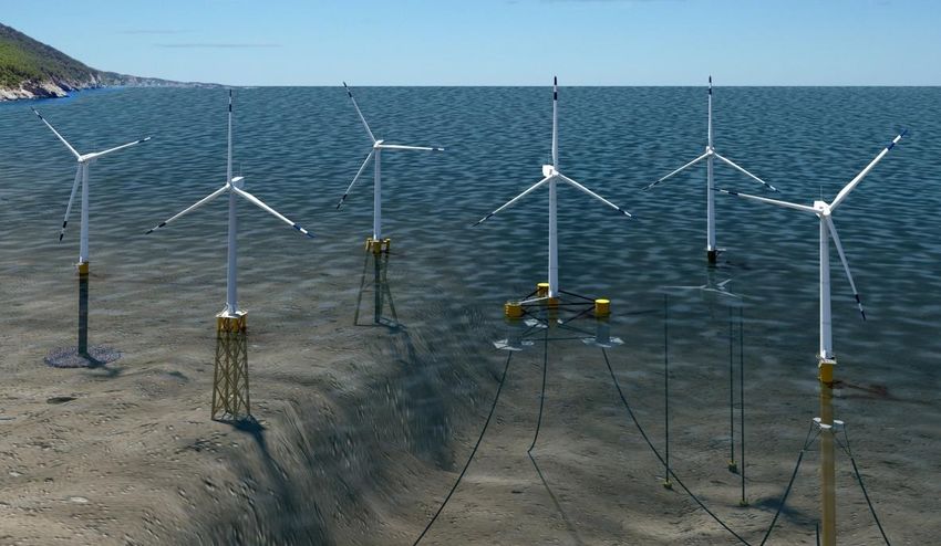
industry, such as deep-water spar and tension leg designs. Figure 1 shows examples of different types of
offshore wind foundations.
Figure 1: Offshore wind foundation types
Left to right: Monopile, jacket, twisted tripod, floating semi-submersible, floating tension leg platform, and
floating spar. (Illustration by Josh Bauer/NREL – Department of Energy)
The following sections provide overviews and descriptions of various foundation types. For each
foundation type, descriptions include diagrams, typical dimensions, component materials, common
water depths, depths of embedment below the seabed, and typical scour3 protections for the foundation,
if applicable. Descriptions also discuss installation methods and siting considerations, such as water
depth and seabed geology.
Each foundation type is designed to support the portions of the wind turbine that are above sea level: the
wind turbine tower, the nacelle4 that contains the generator, the rotor hub, and the turbine blades. The
foundation must be able to resist two types of stressors:
• Vertical loads from the weight of the wind turbine components
• Horizontal loads from the force of the winds, ocean currents, and waves
The foundation must resist the vertical loads to keep the wind turbine from sinking into the sea and must
resist the horizontal loads to keep it from sliding on the seabed or being pushed over.
Another essential consideration when selecting a foundation type is how many turbines to site within a
particular area. An effective windfarm utilizes as many as possible after considering the amount of
energy generated versus the cost of the installation and making sure people are still able to enjoy ocean-
3
Scour is the removal of sediments from around moorings and piers caused by movement of water around hard
structures. Scour holes compromise structural integrity and are one of the main causes of structure failures in water.
4
A nacelle is a structure that holds engines, fuel, or equipment.
3based recreational activities. Appropriate turbine spacing helps balance energy generation with cost,
while accommodating other maritime uses.
The spacing between turbines in a row is typically between 5 and 10 rotor diameters, which change
according to the size of the turbine. The rows are typically spaced between 7 and 12 rotor diameters
apart in the direction of the prevailing wind (Baring-Gould 2014). As a result, offshore wind turbines
are spaced between 0.55 and 1.1 kilometers (km) (0.3 and 0.6 nautical mile5) apart, with the spacing
expected to grow as turbine and rotor size increase (BOEM 2015).
The proposed Vineyard Wind project evaluated spacing options between wind turbine generators
(WTGs) of approximately 1.4 to 1.9 kilometer (km) (0.75 to 1 NM). The U.S. Coast Guard recommends
spacing offshore turbines on a 1-NM grid in the MA/RI Wind Energy Areas, where the project was
located, to maintain maritime safety and ease of navigation MARIPARS 2020); Vineyard Wind has
stated they will use this spacing. BOEM expects a 1-NM grid spacing for all other projects in the Rhode
Island and Massachusetts lease areas. The type of foundation does not have a significant impact on the
turbine spacing.
2.1 Monopile Foundations
2.1.1 Description
Figure 2: Monopile foundation
Worldwide, most offshore windfarms use monopile foundations, which consist of a single, large-
diameter steel pipe, known as a pile, that is driven into the seabed to provide vertical and lateral support.
Soil resistance at the end of the monopile and side friction between the pile and the soil combine to
carry the vertical loads. The horizontal loads are carried by the monopile’s resistance to bending and by
the lateral resistance of the soil surrounding the embedded portion of the monopile.
The size of the monopile depends on the water depth, the strength of the seabed soils, the size and
weight of the wind turbine, the area swept by the wind turbine blades, and the expected wind, wave, and
5
One nautical mile = 1.1508 statute (land-measured) miles or 6,076 ft.
4current forces acting on the structure at the installation site. Table 2provides information about
monopile dimensions and project characteristics. Current designs include steel monopiles up to about 10
m (33 ft) in diameter. So far, monopiles have been used or proposed for use in water up to 50 m (164 ft)
deep (BOEM 2020), but designers expect monopile technology will be feasible in waters up to 60 m
(200 ft) deep (LEANWIND 2017).
Ocean currents around and past the monopile can remove or scour the natural seabed soils from around
the monopile, creating a depression or void. Because a monopile depends on this soil for its lateral
resistance, designers incorporate scour protection around the base of the monopile, typically a rock
blanket, which is a layer created from stones that are large enough to resist scour. For a large monopile,
a rock blanket may be about 50 m (164 ft) in diameter and 1–1.5 m (3–5 ft) thick.
For example, a turbine with a 150-m (492-ft) rotor diameter, a midrange turbine spacing of 7.5 rotor
diameters (1.05 km or 3,690 ft) between turbines, and 9.5 rotor diameters (1.4 km or 4,674 ft) between
rows would cover about 160 hectares (396 acres) of seabed per turbine. A 50-m (164-ft)-diameter rock
blanket for scour protection would cover about 0.2 hectares (0.5 acre) or slightly more than 0.1 percent
of the seabed within that turbine spacing.
After analyzing the scour-protection footprints for offshore windfarm plans submitted to BOEM, it was
determined that the scour protection for a 12 MW monopile would disturb 0.34 hectares (0.85 acres)
(BOEM 2020), which would equal 0.1 percent of the seabed within a windfarm site’s total area based on
a 1-NM turbine grid spacing.
2.1.2 Installation
Monopiles are typically prefabricated and transported to the site as a single structure. The depth of
embedment below the seabed is comparable to the water depth, so the length of a monopile can exceed
80 m (260 ft). A 9-m (30-ft)-diameter pile could have a wall thickness of about 100 millimeters (mm) (4
inches) and weigh more than 680 metric tonnes (1,500 short tons)6.
Large cranes mounted on specialty installation vessels are necessary for handling these large, heavy
monopile structures. The piles must be carefully positioned at the planned location, maneuvered to a
vertical position, and lowered to the seabed. The seabed does not require any advance preparation. The
monopiles initially sink into the seabed under their own weight but must then be hammered or vibrated to
their design depth. The pile driving can deform or distort the top of the pile, so a separate, roughly
cylindrical transition piece is often slipped over the top of the monopile and permanently fixed with a
cement grout (Hammar et al. 2008).
Marine sediments that consist primarily of sands and clays are most suitable for monopile installation
with pile-driving hammers or vibratory methods. Monopiles are less practical and may not be an
economical foundation alternative at sites containing shallow bedrock or strata containing boulders,
cobbles, or coarse gravel that can prevent the pile from reaching its design depth during driving.
In difficult soil conditions, monopiles can be drilled instead of driven. In the United Kingdom, the
company LDD provided specialty relief drilling services at the Gwynt y Môr windfarm off the coast of
North Wales from 2012 to 2014 to help install monopiles up to 6 m (20 ft) in diameter. The reverse-
circulation drilling system is capable of handling piles up to 8 m (26 ft) in diameter (LDD 2020). Drilled
monopile installation is also being explored for concrete monopiles (Desemberg 2014).
Monopile installation used to require carefully coordinated anchoring configurations to maintain station-
keeping for the installation vessels during pile driving. Newer specialty installation vessels use dynamic
6
The British metric tonne is 2,240 pounds (1,016 kg), and the U.S./Canadian ton is 2,000 pounds (907 kg). To avoid
confusion, the British tonne is referred to as the long ton, and the U.S./Canadian ton as the short ton.
5positioning, which eliminates complex anchor-handling operations and allows the installation of even a
large monopile in just a few hours.
Table 2: Sample offshore wind projects with monopile foundations
Project Turbine MW Water Depths Monopile Diameter
North Hoyle 2 7–11m (23–36 ft) 4.2 m (14 ft)
Utgrunden I 1.5 -- 3 m (10 ft)
Utgrunden II 3.0 20 m (66 ft) 5.4 m (18 ft)
Borkum Riffgrund, Germany 4.5 30 m (98 ft) 6 m (20 ft)
Monopile foundations installed before 2007 -- -- 3–4 m (10–13 ft)
New 8 MW (as of 2017) turbines 8.0 -- 7 m (23 ft)
Horns Rev 1 -- 6–14 m (20–46 ft) 4 m (13 ft)
Vineyard Wind I, Massachusetts 9.5 37–49.5 m (121–162 ft) 7.5–10.3m (25–34 ft)
Sources: BOEM 2017; BOEM 2020; Hammar et al. 2008; and Zucco 2006
2.2 Jacket Foundations
2.2.1 Description
Figure 3: Jacket foundation
Jacket foundations are lattice-truss structures similar to the designs of many offshore oil platforms. The
jackets are usually four-legged, with tubular legs at the corners and smaller-diameter horizontal cross
pieces and diagonal struts welded between the legs to provide rigidity. The diameters of the tubular steel
members that form the legs, often 1 to 3 m (3.3 to 10 ft), are much smaller than those of monopiles.
Above the waterline, a steel transition piece distributes the weight of the turbine tower and turbine to the
jacket. The jackets are normally fixed in place using pipe piles, which transfer the vertical loads to the
seabed. Horizontal forces create an overturning moment, which the piles counteract by a combination of
6compression and tension in the piles. The weight of the jacket and of the wind turbine also resist the
overturning forces.
Table 3 provides data on jacket-foundation dimensions and project characteristics. Jacket foundations
for offshore wind turbines have been used in waters from less than 5 m (for demonstration projects), but
are most applicable for water depths between 30 to 60 m (100 to 200 ft) (Musial et al. 2006). In the oil
and gas industry, which has a tremendous amount of experience with jacket foundations, larger jacket
platforms have as many as 12 legs and have been used in waters over 400 m (1,300 ft) deep. The first
commercial offshore windfarm in the U.S., the Block Island Wind Farm, uses jacket foundations.
2.2.2 Installation
Jacket foundations are typically built in a shipyard or other shoreside facility, and then transported to the
site on a flat-top barge or specialty transport vessel. Jackets can also be floated and towed to the site. At
the site, the jacket must be upended into a vertical position with large cranes or by controlled sinking,
and then carefully lowered to the seabed. The jacket may be placed directly on the seabed before pile
driving or on a previously positioned template after piles have been driven through the template guides.
Pipe piles are then either driven through the hollow, tubular jacket legs or installed as skirt piles through
external pile guides at the toe of the jacket. After driving, the piles are then grouted into place. The piles
are much smaller in diameter than monopiles and can be installed with smaller driving equipment.
Jacket-foundation piles are well suited for stiff clays and medium-to-dense sands that can help generate
the necessary friction along the length of the driven piles. They also work well in softer soils, such as
silts and clay, but may require longer lengths to develop enough friction resistance. These piles are also
effective where very soft sediments overlay stiffer soils or bedrock, provided the piles can develop
sufficient tensile resistance. Piles are not well suited for locations with boulders.
Jackets may also be anchored to the seabed using suction caissons, a type of watertight retaining
structure. Suction caissons are similar to large-diameter pipe piles, but instead of being hammered or
vibrated into position, they are forced below the seabed by reducing the pressure within the caisson and
leveraging the pressure of the ocean to force the caissons into the soil. The suction caissons transfer the
loads to the seabed soils similarly to piles, but the caissons are larger in diameter and shorter in length.
Jacket foundations with suction caissons are sometimes called suction bucket jackets.
Table 3: Sample offshore wind projects with jacket foundations
Turbine Base
Project Water Depths Pile or Leg Diameter
MW Dimension
Tamra 3 4–9 m (13–30 ft) -- --
Utgrunden II (Baltic Sea) 3 20 m (66 ft) 1.5 m (5 ft) --
Beatrice (North Sea) 5 48 m (157 ft) 1.8 m (6 ft) 20 m x 20 m
(66 ft x 66 ft)
Block Island 6 23–28 m (75–92 ft) 1.8 m (6 ft) 18 m x 18 m
(60 ft x 60 ft)
Alpha Ventus 5 28–30 m (92–98 ft) 2.5 m (8 ft) --
Sources: SMITH ET AL. 2015, 2017; English et al. 2017; Hammar et al. 2008; Sif 2020; Zucco 2006.
72.3 Tripod Foundations
2.3.1 Description
Figure 4: Tripod foundation
A tripod foundation adopts some characteristics of a jacket foundation and some of a monopile. It has a
tetrahedral (pyramid-shaped) space frame constructed from tubular steel members. Like a jacket
foundation, piles or suction caissons at the corners of the triangular base anchor the foundation to the
seabed. The legs are typically 20 m (66 ft) to 40 m (131 ft) apart (Desemberg 2014), and a diagonal
brace connects each leg to a cylindrical central column that is similar to a monopile, except that the
central column does not enter the seabed. Additional tubular structural members connect the three legs
together and provide additional support for the central column, which rises above the waterline to
provide a base for the turbine tower.
The three-legged tripod base transfers the vertical loads to the seabed through the piles or suction
caissons. As in a jacket foundation, horizontal forces create an overturning moment, which is resisted by
a combination of compression and tension forces carried from the piles or caissons to the seabed soils.
The bracing that connects the central column and the legs allows the central column to be smaller in
diameter than a monopile.
2.3.2 Installation
The construction sequence for a tripod is similar to that of a jacket foundation. The tripod base and the
central column would be constructed onshore as a single unit, transported to the site, oriented vertically,
and lowered to the seabed. The piles are then driven through the pile sleeves. The seabed does not
require any advance preparation prior to installation.
As with jacket installation, tripods fixed with piles are well suited for sites with stiff clays and medium-
to-dense sands and could be used in softer soils, but they are not well suited for locations with boulders.
Tripods may also be anchored to the seabed using suction caissons in suitable soils. Scour protection
8may be required around the base of the tripod in areas with high bottom currents or easily erodible
sediment.
Table 4: Sample offshore wind projects with tripod foundations
Project Turbine MW Water Depths Pile or Leg Diameter Base Dimension
Design Estimate 3 20 m (66 ft) -- --
Design Estimate -- 40 m (131 ft) -- --
Alpha Ventus 5 28–30 m (92–98 ft) 2.6 m (8.5 ft) --
Global Tech 1 5 38–41 m (125–135 ft) 2.5 m (8.2 ft) --
Borkum West II 5 33 m (108 ft) 2.5 m (8.2 ft) --
Sources: Hammar et al. 2008; BOEM 2017; English et al. 2017.
2.4 Tri-pile Foundations
2.4.1 Description
Figure 5: Tri-pile foundation
A tri-pile foundation consists of three cylindrical pile legs that connect to a transition piece above the
waterline, forming a space frame that supports the wind turbine tower and turbine. The transition piece
could also connect the three piles below the waterline to support a tower that rises above the water
surface. Tri-pile foundations incorporate some of the features of a monopile foundation and some of a
tripod foundation. The legs are similar to monopiles, but smaller, typically about 3 m (10 ft) in diameter.
The three legs distribute the load over a larger footprint, similar to the base of a tripod foundation.
The three piles transfer the vertical loads to the seabed. As with a tripod foundation, horizontal forces
create an overturning moment that is resisted by a combination of compression and tension forces
carried by the piles to the seabed soils and by the stiffness of the three piles.
9The footprint of the tri-pile foundation depends on the water depth, the wind and hydrodynamic loads,
the geological conditions, the pile diameters, and the depth of pule embedment. Tri-pile foundations
have been used in waters from 25 to 40 m (80 to 130 ft)-deep (Sánchez et al. 2019).
2.4.2 Installation
The foundation piles and the transition piece are fabricated as separate components for transport to the
offshore turbine site. The piles are lifted from the transport vessel by crane, but the required crane size
to lift and position the piles is much smaller than the size required for a monopile, due to the smaller
pile diameter and lower weight. Similarly, smaller pile-driving equipment is required. As the three
foundation piles are hammered or vibrated into the seabed, a guide frame maintains the proper
alignment so that the transition piece fits atop the piles. The piles are connected by the transition piece,
which is grouted into place.
In areas with high bottom currents or easily erodible sediment, scour protection may be required around
the legs of the tri-pile foundation.
Table 5: Sample offshore wind projects with tri-pile foundations
Pile or Leg
Project Turbine MW Water Depths Base Dimension
Diameter
Hooksiel 5 2–8 m (7–26 ft) 3.4 m (11 ft) --
BARD Offshore I 5 40 m (130 ft) 3.4 m (11 ft) --
Veja Mate 6 39–42 m (128–138 ft) -- 20 m (66 ft)
Clearcamp 5 29–33 m (95–108 ft) -- --
Sources: Buck et al. 2017; OSPAR 2018; Sif 2020
2.5 Jack-Up Foundations
2.5.1 Description
Figure 6: Jack-up foundation
10Jack-up foundations are similar to jack-up drilling rigs and platforms that have been used in the offshore
oil and gas industry for decades and now have been proposed for offshore wind projects. A jack-up
foundation consists of a floatable platform with three or four legs that can be raised and lowered relative
to the platform. When lowered, the jack-up legs pierce the seabed under the weight of the structure, plus
the weight of any additional temporary ballast water. Footings or spud cans on the legs help to distribute
the loads from the legs to the soil. Once the legs are set, ballast water is drained and the hull is jacked-
up above the water surface to its operational height (Lafferty 2011).
As with tri-pile foundations, the spacing of the legs on jack-up foundations contributes to the platform’s
stability against overturning forces. Jack-up foundations for offshore wind have been proposed for water
depths up to 100 m (330 ft) (OWPST 2020).
2.5.2 Installation
Jack-up platforms are constructed in port as floatable hulls. The turbine tower, rotor, and blades are
installed on the hulls before deployment. Because they float, the entire assembly can be towed to the
windfarm site by oceangoing tugs.
One of the benefits of jack-up platforms is that installation does not require any heavy-lift vessels or
specialized installation vessels at the site. The legs are jacked into the seabed until they find enough
resistance to raise the platform above the water level without the need for pile driving. To accommodate
different types of soil or uneven seabed conditions, the extension of each leg can be controlled
independently to maintain a level platform. When the platform reaches its design height, the legs are
locked into place. Unlike other fixed-bottom designs, jack-up platforms can be decommissioned simply
by “jacking up” the legs and towing the platform away (Lafferty 2011).
Jack-up foundation piles are well suited for hard bottom-conditions and stiff clays and medium-to-dense
sands that can easily support the weight of the structure. They can also work in softer soils, such as silts
and softer clays, but may require longer leg lengths and deeper penetration into the seabed to develop
enough resistance.
In areas with high bottom currents or easily erodible sediment, scour protection may be required around
the legs of the jack-up foundation.
Currently, there are no commercial wind turbines that use this type of foundation, but a jack-up platform
was used for the foundation of a meteorological mast for an offshore wind farm in the Baltic Sea (Eric
Haller Oil & Gas Corp. 2020).
112.6 Suction Bucket Foundations
2.6.1 Description
Figure 7: Suction bucket foundation
Suction bucket foundations - also called mono bucket foundations or monopods - are essentially very
large-diameter suction caissons. Unlike a suction bucket jacket foundation in which multiple suction
caissons may be used instead of piles, a suction bucket foundation acts as a single, integral base for the
entire foundation. In its simplest form, a suction bucket foundation is a cylinder with an open bottom
and a closed top and of a wide enough diameter to resist the overturning moments applied to the
structure.
As with suction caissons, suction bucket foundations are forced below the seabed by pumping out water
to reduce the pressure within the base and allowing the hydrostatic pressure of the ocean to force the
suction bucket into the soil. The suction bucket resists vertical loads primarily by frictional resistance
between the caisson walls and the soil. The overturning moments are resisted by the wide footprint of
the base.
Suction bucket foundations can create a wide, solid obstruction to current flow, leading to scour around
the perimeter of the bucket, especially in sandy strata or where current wind speeds are high. Loss of
soil reduces the frictional resistance of the foundation. Scour can also shorten the effective length of the
flow path between the inside and outside of the bucket, weakening the ability to develop suction. To be
effective, the design of suction bucket foundations must account for scour potential and include
adequate scour protection, usually a rock blanket around the foundation and extending beyond the
perimeter skirt.
122.6.2 Installation
Suction bucket foundations can be transported to the site on flat-top barges or vessels, but they can also
be designed to be floated and towed. At the site, the foundations are maneuvered to an upright position
and carefully lowered to the seabed through controlled flooding and using control lines. Once the rim of
the suction bucket begins to penetrate the seabed under its own weight, subsea pumps on remotely
operated vehicles (ROVs) create a pressure differential by pumping water out of the suction bucket and
forcing it deeper into the seabed. Suction bucket foundations are best suited for sediments like medium-
stiff clays and fine-to-medium sand. Cobbles, boulders, or coarse gravel layers can interfere with the
suction, and very soft soils may not provide enough resistance for stability.
Currently, there are no commercial facilities that use this type of foundation. A 2019 pilot demonstrator
project for two suction bucket foundations at the Deutsche Bucht offshore wind project was abandoned
in 2020 (Northland Power 2020).
2.7 Gravity Foundations
2.7.1 Description
Figure 8: Gravity foundation
Gravity foundations are structures with wide, heavy bases that sit on the seafloor and support the
cylindrical central column that rises above the waterline. The base is most commonly made of
reinforced concrete, but steel designs are also used. The gravity base supports the vertical loads of the
wind turbine by direct contact pressure with the seabed. The overturning moment created by horizontal
forces is counteracted by the weight of the base and the rest of the turbine structure.
The dimensions of a gravity foundation depend on the water depth and the expected wind, wave, and
current forces acting on the structure. As rotor diameter, turbine hub, and water depth increase,
overturning forces and moments rise substantially, so gravity foundations have generally been limited to
smaller turbines in shallow to medium waters (less than 20 m or 65 ft deep), but have been used in
waters up to 30 m (98 ft) deep (Desemberg 2014).
13Because of the wide, solid base that interrupts current flow, scour protection is needed around the
gravity base if the foundation soils are erodible. At the Lillgrund Wind Farm, off the coast of Sweden,
scour protection consisted of a rock blanket with up to 350-mm (14-inch)-diameter stones extending up
to 8 m (26 ft) beyond the gravity base (Hammar et al. 2008).
2.7.2 Installation
Gravity bases require more seabed preparation than other foundation types. The installation site must be
flat and level, so the seabed is often dredged in preparation for foundation placement. Dredging creates a
depression or pit in the seafloor. The site may be dredged several meters below the mudline to remove
weak soils or provide additional resistance through embedment. Embedment can also be enhanced by
including a perimeter steel skirt as part of the base. Because gravity bases do not always require
embedment, they can be used in locations not suitable for pile foundations, like sites with shallow
bedrock or boulders. A gravel pad may be built up on the seabed to provide a uniform foundation before
positioning the base.
For Thornton Bank Offshore Wind Farm, Phase I, the turbine grid spacing—500 m (1,640 ft) along a
row and 700 m (2,300 ft) between rows—gives an area of seabed per turbine of 35 hectares (86 acres).
The foundation pits for the 23.5-m (77-ft)-diameter gravity bases were dredged 7 m (23 ft) below the
seabed and, including the pit side slopes, covered an area 192 m (630 ft) by 120 m (394 ft), or 2.3
hectares (5.7 acres), disturbing nearly 7 percent of the seabed within the windfarm area
(Peire et al. 2009).
Gravity bases are built onshore, often at a drydock. Before they are ballasted, the bases are buoyant
enough to float, which allows them to be towed to the site and eliminates the need for a large transport
vessel and heavy lift cranes. The bases are sunk via controlled flooding and maintained at near neutral
buoyancy until set in place. The gravity base is then ballasted with sand, stones, concrete, or iron ore.
The central column, typically about 5 m (16.4 ft) in diameter, may also be ballasted to increase the
overall weight and stability of the structure. Grout may be injected below the gravity base to further
increase the stability of the foundation. The foundation pit is then backfilled, and the scour protection
placed around the foundation.
Table 6: Sample offshore wind projects with gravity foundations
Project Turbine MW Water Depths Base Diameter
Middelgrunden 2 4–9 m (13–30 ft) 16.5–19 m (54–62 ft)
Vindeby 0.45 2–4 m (7–13 ft) --
Lillgrund 2.3 4–9 m (13–30 ft) 16.5–19 m (54–62 ft)
Nysted II (Rodsand II) 2.3 6–12 m (20–40 ft) --
Thornton Bank OWF I 5 20–26m (66–85 ft) 23.5 m (77 ft)
Nysted I (Rodsand I) 2.3 6–9 m (20–30 ft) 11 m (36 ft)
Sources: Baring-Gould 2014; English et al. 2017; Hammar et al. 2008; Peire et al. 2009; van Wijngaarden 2017.
14You can also read