Controlled Aerodynamic Loads on a Slender Axisymmetric Body at High Incidence - Bojan Vukasinovic
←
→
Page content transcription
If your browser does not render page correctly, please read the page content below
AIAA-2021-1943
Controlled Aerodynamic Loads
on a Slender Axisymmetric Body at High Incidence
Edward Lee 1, You Huang 2, Bojan Vukasinovic3, and Ari Glezer4
Woodruff School of Mechanical Engineering,
Georgia Institute of Technology, Atlanta, GA 30332-0405
Abstract
The flow over an inclined slender axisymmetric cylinder (L/D = 11) with an
ogive forebody is investigated experimentally at high angles of attack up to
= 65. Of particular interest is the evolution and control of net side forces that
are associated with asymmetries of the forebody vortices. It is shown that the
interactions of the forebody vortices with the near-wake vortices of the
cylinder leads to the formation of a vertical stack of counter-rotating
streamwise vortices whose order depends on the dominant asymmetry of the
forebody vortex pair. Synthetic jet actuation applied at the juncture of the
forebody leads reversal of the order of the vortex stack in the wake and
consequently alters the net side force. The present investigations also
demonstrated that unsteady coupling between the cylindrical body and its
near wake can lead to strong yaw-roll instabilities. The manipulation of the
body vortex system and the side force by flow control actuation can be used
for bi-directional control of the body's trajectory and suppress this instability.
I. Background
Investigations of the aerodynamic characteristics of axisymmetric slender bodies at moderate and
high incidence angles have been largely motivated by the flight dynamics of missiles, munitions,
and fighter aircraft. These flight platforms encounter complex, unsteady aerodynamic loads that are
usually far more significant at higher angles of attack and are associated with the appearance and
evolution of trains of spatially and temporally varying vortical structures over the body and in its
near wake. The earlier studies showed that these vortical structures are spearheaded by the formation
and asymmetries of counter-rotating vortex pairs near the upstream end of the forebody. The
dynamics and asymmetries of these forebody vortices and their interactions with vorticity
concentrations within the oblique shear layers that bound each side of the near wake along the main
cylindrical body and its aft segment can contribute to strong unsteady side- and cross-stream forces
and yawing and pitching moments that may be used for attitude control.
1
Graduate Research Assistant, AIAA Member.
2
Graduate Research Assistant, AIAA Member.
3
Research Engineer, AIAA Member.
4
Professor, AIAA Fellow.
1
American Institute of Aeronautics and Astronautics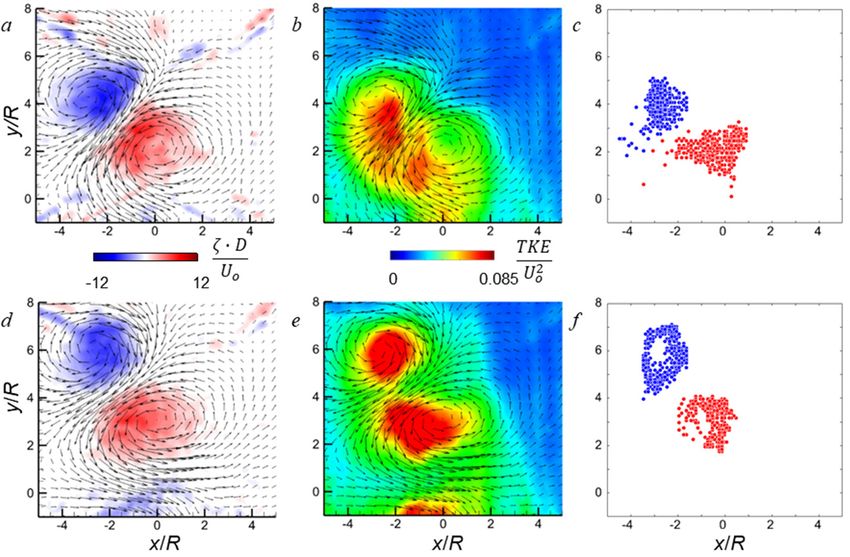
AIAA-2021-1943
In one of the early investigations of the forebody vortices, Nelson and Fleeman (1975) attributed
the induced changes in side force and yawing moment on the cylinder to asymmetric shedding of
vortices from its leeward side. Yanta and Wardlaw (1977) noted the asymmetry of the forebody
vortices and flow at high inclination angles can be caused by minor variations of the nominally
axisymmetric forebody, and in a subsequent investigation (Yanta and Wardlaw, 1981) attributed
the side force that occurs when one of the forebody vortices detaches from the body to the opposite
sense vortex that remains attached. Subsequently, these authors found that the asymmetric vortex
pattern ( = 45) is formed as a result of secondary vortices that develop adjacent to the primary
forebody vortices, causing one of the primary vortices to become detached from the surface (Yanta
and Wardlaw 1982).
Based on simulations and flow visualization studies of the forebody vortex flow over a range of
angles of inclination in various studies (e.g., Wu et al., 1986, Ward and Katz 1989a, 1989b, 1989c,
Zilliac et al. 1991, and Deng et al. 2003), the topology of the forebody vortices over a range of
inclination angles can be divided into three primary regimes. These regimes include: symmetric
vortices that are mostly jointly located adjacent to the surface of the cylinder or become jointly
detached from the surface (α < 30o), asymmetric vortices where one of the counter-rotating
vortices become detached first, leading to mutual roll (30 < α < 60o) and to significant side force
and yawing moment, and unsteady wake-like flow when the vortices couple to the oblique and
Kármán shedding off the cylinder section (60 < α < 90o).
At high angles of attack, simulations of asymmetric vortex shedding induced by a geometric
perturbation on one side of the forebody of a slender ogive-cylinder ( = 70) by Ma and Liu
(2014) showed that the wake of the main cylinder can be roughly divided into two main streamwise
domains. This is consistent with the observations of Thomson and Morrison (1971), where the
upstream (5-7D long) domain comprises of a quasi-steady multi-vortex structure of the forebody
vortex system, and the downstream domain is characterized by Karman vortex shedding. Ma and
Liu (2014) reported a dominant wake frequency associated with each of the forebody and Kármán
vortex shedding domains and noted that as the incidence increases, the upstream domain
diminishes, as it can be expected. It is noteworthy that the simulations of Ma and Liu (2014) reveal
interactions of the forebody vortices with streamwise vortices that form within the oblique shear
layers on each side of the cylinder’s near wake.
In an effort to mitigate asymmetric vortex formation and the associated increase in side forces and
yawing moments, the utility of movable and/or deployable mechanical protrusions for reduction in
aerodynamic side forces and moments has been investigated. Rao et al. (1987) tested deployable
strakes on an isolated forebody (L/D ≈ 5; = 50) and reported large changes in the side forces with
the strakes azimuthal angle that were associated with the formation of a ‘strake vortex’ that remained
close to the forebody, or a larger-scale detached ‘spoiler vortex’. Leu et al. (2005) utilized an array
of inflatable micro-balloon actuators fixed to the surface of a conical forebody (L/D = 5) to induce
the formation of asymmetric vortices and side forces of a desired direction. Stucke (2006)
manipulated the forces, pitch and yaw moments, and roll angle of an inclined axisymmetric body
(L/D = 4, = 50) using spoilers and strakes near the leading edge. More recently, Mahadevan et al.
(2018) triggered and managed the asymmetry of forebody vortices using boundary layer scale
hemispherical protrusions on a highly polished conical forebody.
A number of investigations employed fluidic actuation (steady and unsteady blowing and suction)
and limited plasma actuation near the tip of inclined forebodies to manipulate the shedding of the
2
American Institute of Aeronautics and Astronautics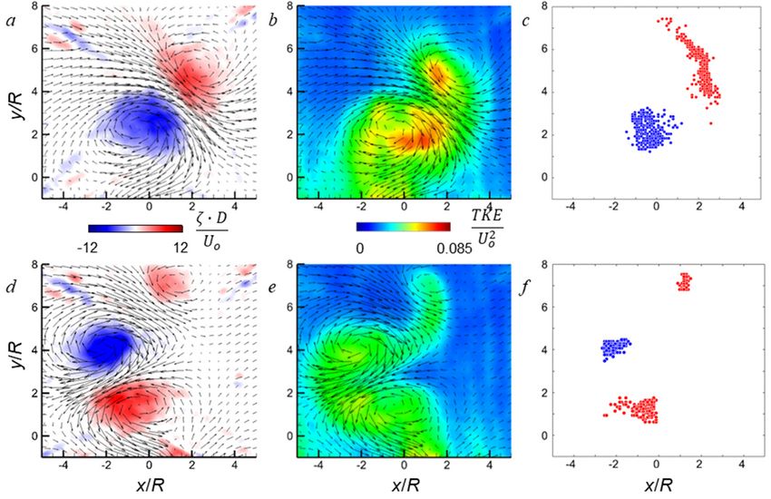
AIAA-2021-1943
vortices from the leeward surface and thereby effect changes in the side forces and yawing moments.
Steady jets have been used over a range of subsonic and transonic speeds and momentum coefficients
(e.g. Almosnino and Rom, 1981, conical forebody, L/D = 6, = 35 - 55, C < 0.002, and Skow et
al., 1982, ogive forebody, L/D = 3.5, = 35 - 55). Unsteady actuation using a linear array of
synthetic jets along the leeward stagnation line of a conical forebody was used by Williams et al.
(1989) and Williams and Papazian (1991) to form ‘pneumatic’ splitter plate and effect flow
symmetry at = 55°. Similarly, Kalyankar et al. (2018) used unsteady sweeping jets on the side of
an inclined cylinder (L/D = 9, = 60) to alter the separation line on the surface and generate yaw
moment as large as CLN ~ 0.8 with C = 2.7%. The “phantom yaw” effects associated with
asymmetric vortex shedding over a pitching axisymmetric body (L/D = 20) were characterized in
the recent simulations of Schnepf and Schülein (2018), who used steady blowing from a slot along
the side of the body to mimic an ‘aerostrake’ and to mitigate asymmetric vortex shedding and reduce
the aerodynamic side force by 25%. In a noteworthy approach, Sato et al. (2016) were able to reduce
the side force and yawing moment on a cone-body (L/D = 5.7, < 90) by up to 50% by using
autonomous bleed driven through internal passages within a forebody cone by the external pressure
differences. Plasma actuation was used by Fagley et al. (2012) to manipulate the asymmetric
aerodynamic side force on an inclined forebody (Kármán ogive, L/D = 3.5, 40< < 60) by up to
Cy = ±1. Considering the effectiveness of active actuation, a number of investigations have
demonstrated closed-loop feedback control of the aerodynamic side forces induced by the forebody
vortices. For example, the methodology of Porter et al. (2014) was recently adopted by Seidel et al.
(2018) in a simulated closed loop feedback controller which could effect specified side forces.
The present investigation explores prescribed modification of the global unsteady aerodynamic
loads on a slender axisymmetric body at high incidence by exploiting the coupled body-wake
instabilities using aerodynamic flow control approaches. These investigations build on earlier
findings of the effects of fluidic actuation on the aerodynamic loads on stationary and moving
axisymmetric bluff bodies at low incidence (cf., Lambert et al., 2018). Although the most prior
work considered the direct control of the forebody vortex pair by placing the flow control elements
in the vicinity of their origin, the present effort focuses rather on the direct control of the coupled
wake, which importance rises to the forefront with increasing incidence. Therefore, the present
flow control approach affects the dominant streamwise vortices, and consequently the
aerodynamic loads, in an indirect fashion.
II. Experimental Setup and Procedures
The present experimental investigation is concerned with the flow dynamics over a slender
axisymmetric cylinder model (L/D = 11, D = 40 mm, Re = 7.9ꞏ104), including the tangent ogive
D
forebody of the length l/D =2. As the prior studies indicated that the ogive body geometry
generally induces more prominent side forces when compared to the conical forebodies (e.g.,
Chapman et al, 1976), the ogive geometry is utilized in the current investigation. The
investigations are focused on control of autonomously-formed forebody vortices over a range of
angles of inclination (25° < < 65°), while the wind tunnel was operated with uniform wind speed
o
of Uo = 30 m/s, while the emphasis is placed on the high angle range 45° < < 65°.o
3
American Institute of Aeronautics and Astronautics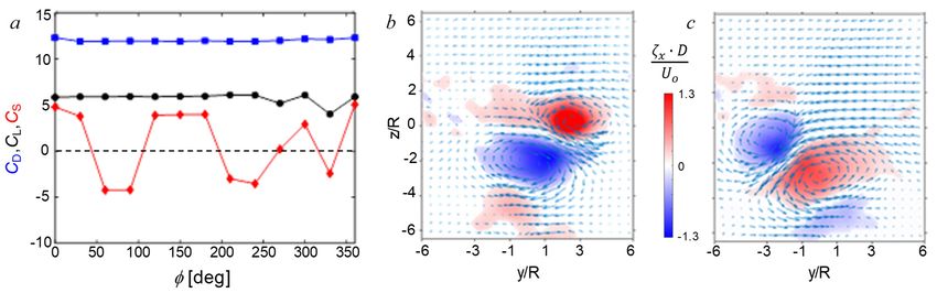
AIAA-2021-1943
The axisymmetric body is comprised of
three major modules: the ogive forebody,
synthetic jet actuator module, and the
central cylindrical body, as illustrated in
Figure 1a. Both the forebody and the jet
module are designed such that can be
rotated by the full azimuthal period. The
Figure 1. Axisymmetric slender model (L/D = 11) with an azimuthal orientation of the forebody
ogive forebody having an integrated flow control module (a)
and surface oil-flow visualization of the forebody vortices at an
and the jet are referenced to the top
angle of attack = 60 (l/D =2). vertical point, with the angles increasing
clockwise, in the upstream view. The jet
module incorporates a single azimuthal orifice measuring 0.6 15.7 mm, imparting the jet
momentum coefficient C while issuing normal to the surface at the frequency of about 2.3 kHz.
To illustrate the forebody vortices that the control jet is designed to affect, the forebody vortex pair
is visualized over the default l/D = 2 ogive forebody at the angle of attack = 60. For that
purpose, a mixture of a titanium-oxide paint and the linseed oil is applied over the forebody, where
its ratio is iteratively adjusted such that the oil mixture does not shear before the operating flow
condition is attained. After the test section speed reached Uo = 30 m/s, the oil is sheared for about
20 minutes, and the resulting flow pattern is shown in Figure 6b in an upstream view from above.
The two vortical traces are clearly seen in the image, forming off the forebody tip and evolving
along the forebody surface. The strong traces along each line where the vortex lifts the flow away
from the surface indicates that these vortices remain in the proximity of the surface over the full
forebody extent.
The axisymmetric model is wire-supported in an open-return wind tunnel (test section measuring
91 cm on the side) by a dynamic 6-DOF eight-wire (1.2 mm dia.) traversing mechanism described
in detail by Lambert et al. (2016). Each support wire is controlled by an independent servo motor,
with an in-line load cell, and electrical connection for the flow control actuators is provided by
thin wires weaved along the back four support wires while the support wires provide electrical
ground. The forces and moments on the model are calculated from the measured wire tensions
projected onto the model (the resultant aerodynamic loads on the model are calculated relative to
the loads in the absence of cross flow, and accounting for wire drag). The attitude of the model is
commanded by a Matlab Simulink controller, which feedback utilizes inputs from VICON motion-
capture camera system at an update rate of 500 Hz.
Besides providing the feedback signal, the six-
camera motion capture system resolves the spatial
and temporal position of the model at any instant
in time. In an alternate configuration, the feedback
loop can be disconnected and the model ‘locked’ in
the desired attitude. Either configuration is
utilized, depending on the objectives of the studies.
The information regarding the model
position/orientation is used to extract the wire
Figure 2. Schematics of the top view of the orientation and accurately decompose the forces
supported model illustrating the stereo PIV wake measured on each load cell into x, y, and z
measurements and positioning of the Vicon cameras components in real time. In addition to the
for orientation tracking of the model.
measurement of the aerodynamic loads, a stereo
4
American Institute of Aeronautics and Astronautics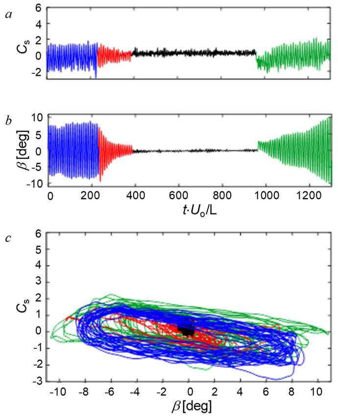
AIAA-2021-1943
PIV (SPIV) system is used to characterize the model’s wake dynamics using two CCD cameras
that are each placed at an angle of 20 relative to an image plane normal to the oncoming flow at
x/D= 2 – 9 from the tip of the model. Schematics in Figure 2 illustrates orientations of the two
PIV and six motion-capture cameras that are distributed evenly on both sides of the test section.
In contrast to many of the prior investigations of fluidic control for affecting the symmetry of the
forebody vortices, in the present investigations the upstream actuation jets were deliberately placed
well downstream of the forebody tip, just downstream from the termination of the forebody, as
illustrated in Figure 1a. The objective was to test whether the evolution of the flow dominant
vortices would be susceptible to a rather indirect control of the coupled wake, instead of controlling
the initial vortex formation at the forebody tip. For the control purpose, a single synthetic jet
actuator (orifice measuring 0.6 15.7 mm) is integrated at the juncture between the forebody and
the cylinder. The jet’s azimuthal orientation is adjustable independently of the forebody
azimuthal orientation .
III. The Base Flow
Initially, the aerodynamic loads on the cylindrical model were characterized in the absence of
actuation over a range of inclination angles (25 < < 65, ReD = 7.9ꞏ104) using the three ogive
forebodies of l/D = 1, 2, and 3. The inclination angle of each model was increased monotonically
from the same base angle to avoid hysteresis effects. In order to enable meaningful comparison
between the models with the different ogive forebodies, the variation of the force coefficients CD,
CL, and CS were computed based on the model’s planform area (including the forebody). Hoerner
and Borst (1985) characterized the lift and drag on an inclined cylinder in the absence of a forebody.
These authors noted that at low inclination ( ≤ 15°), the flow over the cylinder is predominantly
oriented along its axis and it may be thought of as low-aspect-ratio wing with a pair of
counterrotating “tip” vortices that form over the suction surface resulting in lift-induced drag. At
higher angles of attack, the flow from the windward to the leeward face of the cylinder separates on
its leeward face and generates a normal force on the body whose respective cross-stream and
streamwise projections are the lift and drag. Both lift and drag forces are small for ≤ 15°, and as
increases, the drag increases monotonically and reaches a maximum at = 90°, while the lift has
a local maximum (around 55o), and then decreases monotonically and vanishes = 90°.
On the present model, as seen in Figure 3, the drag
1.2
increases monotonically over the entire range of
1
while the rate of increase of the lift begins to
0.8
diminish for > 35° ostensibly as the forebody
0.6
vortices begin to lift off the cylinder and the flow
CD, CL , CS
0.4 from the windward separates on its leeward surface.
0.2 Similar to the observations of Hoerner and Borst
0 (1985), while the drag force continues to increase
-0.2
monotonically, the lift force has a maximum around
-0.4
= 55°, and then decreases at higher angles of
25 30 35 40 45 50 55 60 65 incidence. While the drag coefficients for the three
[deg]
ogive forebodies are nearly identical through
Figure 3. Force coefficients CD, CL, and CS with
~ 60o the drag coefficient of the l/D = 3 ogive is
angle of attack for the slender axisymmetric body
ogive nose ratio l/D = 1 (square), 2 (triangle), and 3 lower at higher and appears to reach a local
(circle). maximum that is lower than the corresponding drag
5
American Institute of Aeronautics and Astronautics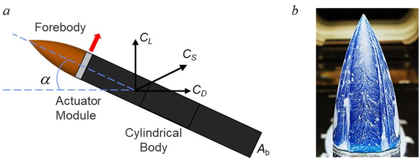
AIAA-2021-1943
coefficients of the l/D = 1 and 2 ogives. However, the corresponding peak lift coefficients of the
l/D = 1 ogive is lower than the coefficients of the other ogives. It is apparent that these changes are
associated the changes in the side forces that remain nominally symmetric about the cylinder’s
vertical (y-z) plane of symmetry up to ~ 50°. According to earlier work (e.g., Keener and
Chapman, 1974), the onset of the vortex asymmetry approximately scales with the forebody tip
angle, which is 58 for the present model. As is evident from the variations of the side force
coefficients, the onset of forebody vortex asymmetry which is affected by small variations in the
ogive surfaces, varies between the different forebody models, and also affects both the lift and drag
forces. For the remainder of the current study, the forebody is fixed at l/D = 2. In addition, it is
observed during the pitch sweeps that the model, once in the non-zero side force domain, can
undergo unstable motion, which is further addressed in Section V.
To gain a better understanding of the base flow features at high angles of attack, preliminary sPIV
measurements are taken at three streamwise positions, measured from the forebody tip, x/D = 2, 5,
and 9 while the body is oriented at = 60. These locations are selected such to characterize the
flow state just downstream from the location of the control jet, far over the body, and finally off the
body, in the wake. Due to the wake spreading, the measurement resolution is adjusted with the
downstream distance, such to capture the wake extent. For the same reason, measurements on the
wake are taken over two measurement planes that are merged into a single composite flow field.
The resulting captured flow field is shown in Figure 4, illustrating the dominant vortical composition
of the flow. As it could be expected, the initial vortex pair, formed at the forebody, lifts off the
surface shortly downstream from the forebody, due to the high incidence. Although still at the surface
at x/D = 2, this pair evolves into a highly asymmetric pair at x/D = 5, where the CW vortex remains
closer to the body, while the CCW vortex, rotated in pair with the CW one, moves away and nearly
atop its CW pair. This relative orientation remains preserved into the wake at x/D = 9. Once the
initial vortex pairs is peeled off, the successive folding of the flow over the cylindrical body results
in the secondary vortex pair formation, which is just barely captured at the bottom end of the
measurement plane at x/D = 5, and fully seen at x/D =9 underneath the primary vortex pair, and
assuming a nearly identical relative orientation between the CW and CCW vortices. Besides these
tow pairs of streamwise vortices, additional vortical
concentrations are seen in the wake, as it is expected that the
shear layers of the flow separating of the cylinder body
partially contribute to the streamwise vortical components.
Besides, each vortex can induce a neighboring lesser
vortical motion of the opposite sense, which is likely
manifested just below the lowest CW vortex at x/D = 9.
The uneven liftoff of the vortex pair and its subsequent tilt
about the common axis signalizes disruption in the side
force balance and induces a net non-zero side force. Such a
liftoff of one of the forebody vortices from the surface was
documented in detail in a number of earlier studies (e.g.,
Lamont and Kennaugh, 1989, DeSpirito 2017, Mahadevan
et al. 2018). Lamont and Kennaugh (1989) showed a nearly
Figure 4. Illustration of the base flow
composition by the sPIV-measured flow
periodic switching in the direction of the side force as the
fields at x/D = 2, 5, and 9, at = 60 and forebody is rotated azimuthally about the axis of the
ReD = 7.9104 (l/D = 2, L/D = 11). cylinder over a range of incidence angles, which reflects the
6
American Institute of Aeronautics and Astronautics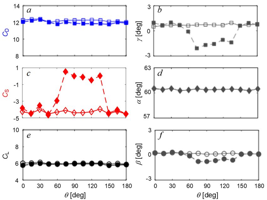
AIAA-2021-1943
switching vortex asymmetry in the flow. As shown by Mahadeven et al. (2018) even fine polishing
of the forebody surface was insufficient to fully suppress the vortex asymmetry and the direction
switch of the induced side force. It should be noted that this sensitivity of the forebody vortices to
small perturbations indicates their potential receptivity to flow control actuation as well.
Figure 5. Force coefficients CD (), CL (●), and CS (♦) with the forebody azimuthal orientation (a), and the two
spanwise mean velocity fields, measured at x/D = 9, with overlaid contour plots of the streamwise vorticity
4
component at = 90 (b) and 180 (c) for the model at = 60 (ReD = 7.910 ).
The asymmetry in the evolution of the forebody vortices and the resulting side forces is investigated
at = 60° (ReD = 7.9ꞏ104) over a full azimuthal rotation of the l/D = 2 forebody. The resulting drag,
lift, and side force coefficients (each normalized by the cylinder’s cross sectional area Ab) are shown
in Figure 5a. In concert with the earlier investigations, the side force exhibits azimuthally-periodic
switching. However, CS > 0 for most of the azimuthal orientations 100o < < 220o, 275o < < 50o
and switches direction CS < 0 only within narrow azimuthal domain centered about = 70o and 220o.
One notable exception is a sudden drop of the side force at = 330, which is caused by the body
undergoing instability for that particular forebody orientation. It is interesting to note that the
induced side force does not change its direction when the forebody is rotated at 180o relative to some
given azimuthal position (i.e., CS > 0 or < 0 at both domains although the nominal magnitudes of the
opposite side forces are not necessarily of the same). That the sense of the side forces does not
change when the forebody is rotated at 180o indicates that the flow asymmetry is likely not brought
about by a random surface imperfection, because a strong periodic behavior of the present data (and
a number of the earlier studies) suggest that the origin of such behavior is likely in the regular
geometry deviation with a preferential axis. The most obvious source of such deviation would be
an imperfect tip of the forebody, particularly since many investigations indicated extreme flow
sensitivity to small geometrical perturbations at the forebody tip. Examination of the tip of the
current forebody model indicated small oval deviation from the perfectly circular termination of the
tip, and it is argued that such an oval shape with the dominant axis would be sufficient to induce
preferential vortex asymmetry, depending on the dominant axis azimuthal orientation. Moreover, as
the forebody is rotated by 180, the oval orientation would assume the same orientation of its
dominant axis, which would explain periodicity is the side force formation. As the oval
manufacturing perturbation is not perfect, this would also explain that asymmetry in the magnitudes
of the excursions and the disparity in their azimuthal extents are associated with the randomness of
this deviation. It is remarkable that for fixed angles of incidence and yaw the lift and the drag are
nearly invariant with even though the side force undergoes significant variations which are
associated with topological changes in the trajectories of the streamwise forebody vortices. This
7
American Institute of Aeronautics and Astronautics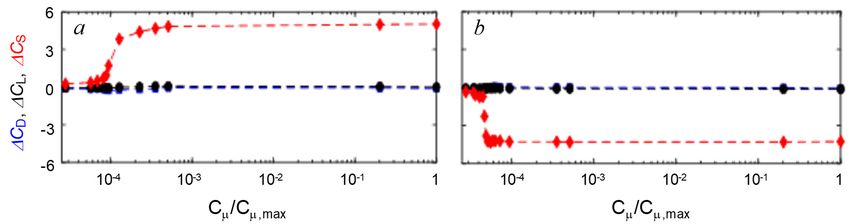
AIAA-2021-1943
indicates that once the vortices separate and migrate off the cylindrical body, their effects on the lift
and drag diminish.
The changes in the topology of the vortex pair associated with the changes in the direction and
magnitude of the side force in Figure 5a is illustrated in color raster plots of the time-averaged
streamwise vorticity superposed with vectors of the cross-stream velocity field captured using stereo
PIV within the domain -6 < y/R < 6, -6.5 < z/R < 6.5 (x/D = 9) for = 90 and 180 (Figure 5b and
c, respectively). The data in each of Figures 5b and c show a dominant pair of counter-rotating
streamwise vortices where the CW vortices in this view are associated with the rollup at the left side
of the forebody (in this upstream view), along with additional, weaker streamwise vortices that
would be shed within the cylinder’s wake (cf. the simulations of DeSpirito 2017). As is evident from
the vorticity concentrations, the major axis of the dominant vortex pair (i.e., the axis centered
between the vortices, nominally normal to a line through the centers of their cores and pointing in
the direction of the induced flow) in Figure 5b is rotated by 128o in Figure 5c (from 26o to 154o).
As can be seen from Figure 5a, the directions of the major axes are asymmetric (i.e., the major axes
in Figures 5b and c are pointing to the right and the left, respectively) and commensurate with the
changes in the directions of the side forces namely CS < 0 at = 90 and CS > 0 at = 180. It is
also noteworthy that the change in the directions of the major axes of the primary vortex pair is also
accompanied by changes in the sense of the accompanying streamwise vortical traces that are
captured within the field of view, ostensibly by reversal of the induced cross flow by the dominant
vortex pair.
IV. Active Flow Control of Aerodynamic Loads
An initial assessment of the flow control effectiveness by a synthetic jet (Section III) is done by
investigation of its performance with respect to its azimuthal orientation for a given flow control
parameter C, and for the fixed azimuthal orientation over a range of the control Cs.
As the analysis of Figure 5 indicated, representatives for the two characteristic side force states
CS < 0 ( = 90) and CS > 0 ( = 180) are sufficient to assess the effectiveness of the flow control.
For brevity, only the = 90 case is presented here. As the base flow exerts a negative side force on
the body in this case ( = 60, Figure 5a), the flow control that would counter such a force is sought
within the 0 < < 180 azimuthal jet
orientations. Having the forebody
azimuthal orientation fixed, the synthetic
jet is successively rotated within this range
and the corresponding forces and angular
orientations measured with the jet being
active and inactive. The resulting data are
shown in Figure 6 in terms of the realized
force coefficients and angular orientations.
As seen in Figures 6a,c,e, there is an
azimuthal range of the flow control
effectiveness, inducing over CS = 4,
while virtually no changes are recorded in
CD and CL. It should be noted that the
Figure 6. Force coefficients CD (a), CS (c) and CL (e) and the flow control completely counters the base
roll (b), pitch (d), and yaw (f) with the jet azimuthal orientation flow side force, restoring the near-zero
at = 60.
8
American Institute of Aeronautics and Astronautics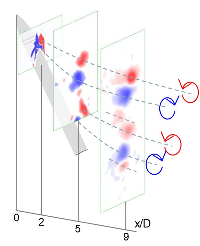
AIAA-2021-1943
net force within 75 < < 135 . Along with the effect on the side force, the flow control effects
changes on the body attitude, as displacements in both yaw and roll are measured. It should be
noted, though, that the split in displacement in yaw and roll is due to the lab-fixed coordinate
system. In the body-oriented coordinate system, most displacement would in its own yaw.
Although not shown, the analogous test for the forebody orientation = 180 results in the flow
control effective range within about mirror-image range of the jet azimuthal angles . Therefore,
for the remainder of this study, the representative flow control jet orientation = 90 is selected
for base flow negative side force (CS < 0) and = 180 for the base flow positive force (CS > 0).
Once the most effective azimuthal flow control orientations are pre-set, the next step concerns the
sensitivity of such preferential azimuthal distance to the full range of the absolute forebody rotation.
To test this, the jet orientation of = 90 is paired with the forebody orientation = 60 (see Figure
6), and then the forebody and the actuator azimuths are jointly reoriented back to zero orientation
for the forebody. After that, both the actuator and the forebody are incremented jointly across the
full span of the azimuthal angles, and the jet effectiveness is tested, keeping in mind that for any
forebody orientation , the jet orientation = + 30. By simultaneous rotation of both the forebody
and the jet, the jet relative distance to the dominant axis of the forebody tip is maintained, while the
tip disturbance imposes its full-rotation effect on the side force. The resulting changes in all the three
force coefficients are shown in Figure 7. As it was the case in the fixed jet orientation, no significant
effect is detected for the drag and lift forces. Initial incremental effect of the side force, as the
forebody orientation assumes = 60 indicates the maximum jet effectiveness, as the jet itself is at
= 90. It is seen that even beyond this orientation, the jet imparts nearly as strong effect as both
the forebody and the jet are rotated for another 30 increment. At the following increment, it is
interesting to note that significant effect is achieved, but of the opposite sign. By examining the
corresponding base flow force at this orientation = 120 (Figure 5a), it is seen that the base flow
force already switched its sign at this orientation, but the flow control jet, although located at =
150 is still capable of countering this now altered vortex asymmetry that brought about the change
is sign of the base side force. As the jet and the forebody continue to advance azimuthally, small
further changes are measured until the forebody orientation reaches = 240, and thereafter there is
practically no jet effect. This is particularly interesting as a strong negative side force is generated
at = 220 – 250 in the base flow (Figure 5a). The reason for the jet ineffectiveness for these
6 orientations is in the fact that the base flow asymmetry is
of the same sense for both = 90 and 240. As shown in
4
Figure 9a, the jet counters these asymmetries when
CD , CL, CS
2 oriented at = 90. However, in the present test, the jet is
oriented exactly on the opposite side of the body and hence
0
ineffective in countering the flow asymmetry at = 220
-2 - 250, i.e., the jet is oriented on the same side with the
body orientation. This study indicates that the flow
-4
0 50 100 150 200 250 300 350 control is clearly sensitive to the particular (albeit
[ deg] unknown) surface disturbance orientation, but that there is
Figure 7. Incremental change in the force still an azimuthal range of the jet orientation that is
coefficients CD (■), CL (■), and CS (■) by the
sufficient to impart significant changes in the side force,
synthetic jet actuation with the forebody
predominantly by countering the naturally induced side
azimuthal orientation while the jet
orientation is maintained at = + 30. force.
9
American Institute of Aeronautics and Astronautics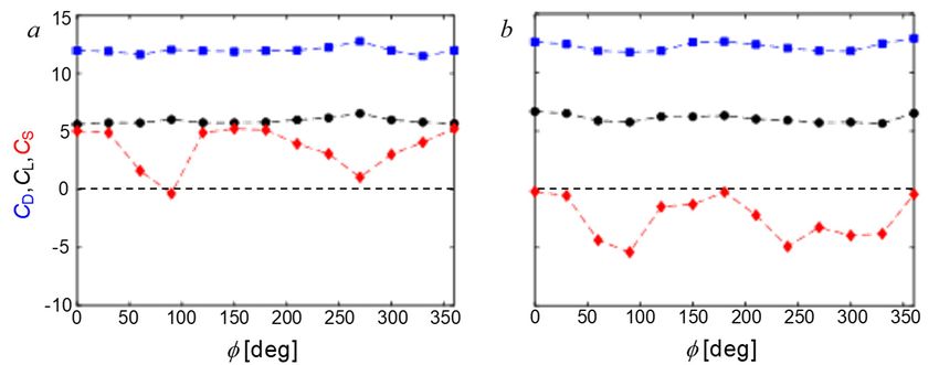
AIAA-2021-1943
Figure 8. Force coefficient change CD, CL, and CS with the control jet for the forebody and jet orientations
(,)= (60 , 90) (a) and (180 , 270) (b).
Lastly, to establishing the optimal flow control coefficient applied to either preferential azimuthal
orientation ( = 90 or 270), coupled to the targeted forebody orientation that results in either a
negative or a positive side force, the flow control parameter is varied over a range of C/C,max and
the changes in the forces are recorded. The resulting changes in the force coefficients are shown
for the negative and positive base side force in Figures 8a and b, respectively. As the flow control
at = 90 (Figure 8a) is designed to counter a negative side force, it facilitates a net increase in
CS. Conversely, the flow control applied at = 270 (Figure 8b) is designed to counter a positive
side force of the base flow and thus generates a net decrease in CS. Common to both cases, it is
shown that effectiveness of the flow control is facilitated at rather low levels of C. Moreover,
there is a rather sharp increase in the induced change in CS within a narrow range of C. Past this
transition there is a saturation level in the achieved CS with further increase in C. This points to
an optimum level of the flow control parameter that achieves the maximum effect. It should be
pointed out that although the current study deploys only a single actuator for the research purposes,
any application would utilize an actuator on either side, such that the bi-directional change in side
forces can be attained on command, without a need for the actuator azimuthal adjustments.
The present concept of
flow control of the
aerodynamic loads relies
on an indirect control of the
dominant vortices that are
the primary source of the
non-zero net side force
(and the yawing moment).
The flow control primarily
Figure 9. Force coefficients CD (), CL (●), and CS (♦) with the forebody
affects the separating flow
at the juncture between the
azimuthal orientation (a), and the flow controlled by the jet at = 90 (a) and
4 forebody and the
270 (b) for the model at = 60 (ReD = 7.910 ).
cylindrical body. The
effect of the actuation was first investigated by exploring the aerodynamic loads in Figure 6. Here,
the effectiveness of the control jet is assessed over a full range of the azimuthal orientations of the
forebody. To address the two characteristic base flow realizations, when the induced net side force
is either negative or positive, the flow control jet is preset at either = 90o or 270 o. When the
synthetic jet actuator was set at an azimuthal angle of = 90o (i.e., pointing to the right in an
upstream view) and the ogive forebody was rotated as in Figure 5a (for = 60, ReD = 7.9ꞏ104), the
(unknown) surface perturbations are essentially varying such to alter the symmetry of the forebody
10
American Institute of Aeronautics and AstronauticsAIAA-2021-1943
vortex pair relative to the azimuthal orientation of the actuation jet. Figure 9a shows the three
resulting global aerodynamic force coefficients at the same azimuthal position relative to the ogive
forebody and cylinder as in the absence of actuation (Figure 5a). These data show that the actuation
significantly alters the magnitude and direction of the induced side forces within the domains
centered about = 90 and 270 while rendering the effect on the side forces throughout the rest of
the azimuthal domain positive but of a much smaller magnitude. The presence of the actuation in
these domains of the high effectiveness reverses the direction of each of the side forces that would
otherwise be induced at = 90 and 270 and alters its sign, therefore implying a change and
reversal in the vortical asymmetry. Overall, actuation by the control jet kept at = 90 results in the
net positive side force, regardless of the forebody orientation. As it could be expected based on the
duality of the effects shown in Figure 8, the opposite arrangement, where the synthetic jet is fixed
on the opposite side ( = 270o) induces exactly the opposite effect to the studied jet orientation at
= 90o (Figure 9a). The mirrored jet predominantly affect the opposing sense of the vortical
asymmetry, thereby significantly opposing the positive side forces, in a similar manner that the jet
Figure 10. Raster contour plots of the mean streamwise vorticity with in-plane mean velocity vectors measured
5
at x/D = 2 (row 1), 5 (row 2), and 9 (row 3) for the base flow ( = 60, ReD = 1.1410 ) at forebody orientation
= 90 (column a) and controlled at = 90 (column b), and for the base flow at = 180 (column c) and controlled
at = 270 (column d). Vorticity contour levels are the same as in Figure 5.
11
American Institute of Aeronautics and AstronauticsAIAA-2021-1943
at = 90o is shown to affect the azimuthal subdomains that induce negative side forces. Therefore,
regardless of the forebody orientation, actuation by the jet at = 270o always induces a negative
side force, as seen in Figure 9b. It is therefore inferred, as already proposed during the discussion
of Figure 8, that integration of the two jets, at = 90o and 270o would be sufficient for control of
either vortical asymmetries. Also, if the objective would be to maintain the side force close to
zero, some tuning of the control jet parameter would be done, as the present results indicate the
“overshooting” of the suppression effect and induction of the side force of the opposite sign.
The main features of the wake flow past a slender body at high angle of incidence were already
discussed in connection with Figure 4. In order to gain insight into the changes in the flow structure
that is associated with each of the opposite side forces that act on the body by each of the control
scenarios depicted in Figure 9, sPIV measurements are acquired at three streamwise cross stream
planes at x/D = 2, 5, and 9 for inclination angle of = 60. The resulting flow fields are shown in
Figure 10 along with overlaid silhouettes of the projected body. Figure 10 includes two pairs of
columns (a, b) and (c, d) for forebody orientations = 90 and 270o, respectively. The columns in
each pair corresponds to the base flow (a and c) and the flow in the presence of actuation when the
actuator is placed azimuthally at = 90 and 270 (b and d, respectively). Rows 1, 2, and 3
correspond to x/D = 2, 5, and 9, respectively. Figures 10.1a and c and 10.1b and d show the effect
of the actuation on the forebody vortices. As can be seen, the two pairs of streamwise vortices
become detached from the surface unevenly and evolve into the asymmetric and tilted pairs, and this
effect is accentuated by the actuation where the CW vortex in Figures 10.1a and b and the CCW
vortex in Figures 10.1c and d begins to turn over the opposite sense vortex. This effects becomes
more pronounced in Figures 10.2a and c. Figures 10.2a, b, c, and d show that in addition to the
forebody vortices there are additional streamwise vortices that are formed by flow separation off the
leeward side of the cylindrical body. In the absence of actuation (Figures 10.2a and c) the secondary,
somewhat weaker (wake) vortices become aligned by the induced flow of the forebody vortices in a
nearly columnar array of counter-rotating vortices. In the presence of actuation, the leading forebody
streamwise vortex (CW and CCW in Figures 10.2a and 10.2c, respectively) become significantly
diffused and weaker (Figures 10.2b and 10.2d), while its pair vortex of the opposite sense (CCW
and CW, respectively) in the column gains in circulation. The induced flow by the intensified CCW
(in Figure 10.2b) and CW (in Figure 10.2d) vortices acts to pull and intensify the next opposite sense
vortex (below) into the column. As shown in Figures 10.3a and 10.3c, the column of alternating
streamwise vortices also forms in the absence of the actuation but it is primarily affected by the
dominant forebody vortex in the surface proximity (CW in Figures 10.2a and 10.3a and CCW in
Figures 10.2c and 10.3c). However, remarkably, the weakening of the leading vortex by the
actuation in Figures 10.2b and 10.2d leads to effective altered order of the vortex stack in Figures
10.3b and 10.3d.
V. Control of the Body Dynamic Coupling to the Wake
As noted in discussion of Figure 5a, coupling to the induced vortices at high angles of attack may
lead to the body unstable response. Up to this point, only the stable body responses were considered.
To survey the possible unstable responses, a continuous pitch up/down maneuver is executed first.
During these tests, the slender model (L/D = 11) is commanded to steadily pitch up from = 45 to
60 followed by the pitch down back to 45. The pitch rates are varied over an order of magnitude,
ranging from 0.1 – 1 deg/s. Although the details of particular onsets and terminations of the model
instability somewhat change with the changing pitching rate, two scenarios emerged as characteristic
for the unsteady body response. In an unsteady-response scenario, depending on the forebody
12
American Institute of Aeronautics and AstronauticsAIAA-2021-1943
Figure 11. Yaw angle variation during the increasing (a,b) and decreasing (c,d) pitch sweep 45 < < 60 for
the forebody azimuthal orientation = 0 (a,c) and 30 (b,d).
azimuthal orientation , the body trajectory may either be initially displaced in yaw but subsequently
recovered (Figures 11a and c), or the body can undergo instability in yaw (and roll), as shown in
Figures 11b and d. The other notable feature is that there is a hysteresis in the onsets and terminations
of instability depending on the pitching direction. This is attributed to the different starting flow
states. When pitching up from = 45, the body wake is still dominated by the forebody vortices,
which peel off of the surface closer to the forebody with the increase in the pitching angle, giving a
way to a more prominent role of the cylinder body wake. When pitching down, the starting wake at
= 60 is in a complex state of the interacting cylinder body shear layers and forebody vortices, and
it would intuitively take longer for such a wake to recover its corresponding more regularized state
(established during the pitch-up motion). It is argued
that this is the main reason for the observed
hysteresis, as both the onset and termination of
instability are delayed relative to their counterparts
during the pitch-up motion. There does not seem to
be any notable difference in terms of the amplitude
of oscillations during the instability, as in both the
pitch up and down, recorded oscillations in yaw
were about = ±5.
The present investigations demonstrated that within
the narrow ranges of angles of incidence
(50o < < 60o) the coupling between the forebody
vortices and the cylinder’s near-wake can lead to
base flow instabilities of the wire-supported model
that is manifested by significant pitch and yaw
oscillations. Although such instabilities may not be
directly detectable on sting-mounted model, the
investigations of Zilliac et al. (1991) indicate their
presence as the azimuthal position of forebody is
Figure 12. Time evolution (a, b) and phase adjusted at ~ 60o. These observations clearly
relationship (c) of the side force coefficient CS and posed the question as to whether manipulation of
the yaw angle for the l/D = 2 forebody model at forebody vortices and therefore their interaction
= 50. Effect of aerodynamic model stabilization by
with the cylinder’s wake vortices can be used to
the jet actuation is shown between 232 < tUo/L <
stabilize or destabilize the model when it is naturally
961.
unstable or stable within this incidence range.
13
American Institute of Aeronautics and AstronauticsAIAA-2021-1943
The present investigation
showed that when the
azimuthal position of the
ogive forebody was set to
= 60o, the model exhibits
significant time-periodic
oscillations in incidence and
yaw (±6o) at incidence of
= 50. As noted in
connection with Figure 5,
when the model is stable in
the absence of actuation
(e.g., at = 60o), CS < 0 and
the major axis of the
forebody vortex pair is
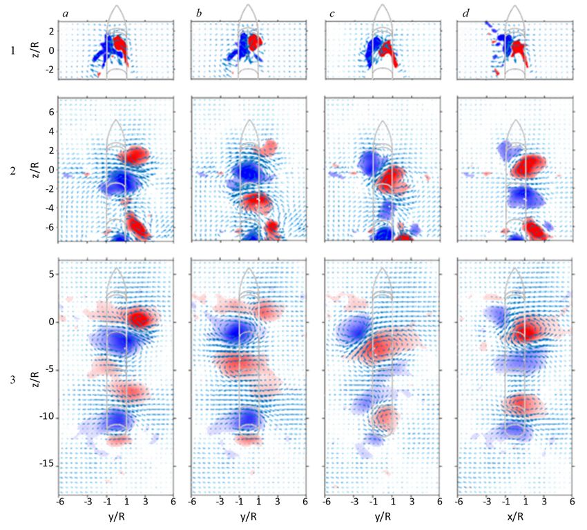
Figure 13. Contour plots of the POD-reconstructed time-averaged vorticity (a, slanted to the left (cf. Figure
d) and turbulent kinetic energy (b, e) fields at x/D = 8, along with the planar 5). Simultaneously-
distributions of the vortex cores (c, f) for the unstable (a– c) and stabilized (d–
f) model dynamics of Fig. 12.
measured time traces of
CS(t) and (t) in Figures 12a
+ +
and b for 0 < t < 232, (t = tUo/L) show that CS oscillates between -2.9 and 1.82 (the nominal mean
is about -0.34) with a characteristic frequency of about 7 Hz (StL = 0.0093). Based on the results of
Section IV, the azimuthal position of the jet relative to the forebody is selected such that it if the
model was stable, it would reverse the symmetry of the forebody vortices ( = 90o), and result in an
increase in the side force. When jet actuation is activated at t+ = 232 through 961, and the traces of
CS(t) and (t) (Figures 12a and b) exhibit a strong decay in oscillations over a characteristic time
t+ = 157 (about 16 oscillations periods), and the peak-to-peak oscillations of CS and are attenuated
by factors of three and five, respectively. While the yaw angle effectively becomes zero, the side
force varies slightly around a mean level of +0.26, indicating that the jet actuation level could be
adjusted so that the effected mean side force vanishes. The time-dependent traces show that when
the jet actuation is terminated at t+ = 961, there is a clear commensurate jump in the magnitudes of
both CS and The unsteady baseline oscillations resume with slowly-increasing magnitude while
the oscillations commence about a negative “offset” in CS which is first negative and then gradually
increases. It is noteworthy that the rate of increase in the amplitude of is slower than in CS
apparently as a result of the model’s inertia. However, it does not appear that the model fully returns
to its original motion before the onset of actuation. This is further accentuated by the CS- phase
plot in Figure 12c, where the trajectory at the end of the model’s response appears offset from the
initial limit cycle. It is also noted that the relatively long transitions associated with the onset and
termination of the actuation might be associated with the gradual coupling (or decoupling) between
the forebody vortices and the vortical structures in the wake of the cylinder.
Color raster plots of the streamwise vorticity downstream of the model (cf., Figure 5) indicate that
the actuation effects significant changes in the vortex topology (Figures 13a and d, respectively).
The unstable model is characterized by the formation of a vortex pair whose major axis is slanted to
the right, and it is remarkable that although the model undergoes unsteady oscillations, the time-
averaged vorticity distributions indicate that the coherence of the vortex pair is largely preserved
although the time-averaged CCW vortex appears weaker and its streamwise vorticity is less
14
American Institute of Aeronautics and AstronauticsAIAA-2021-1943
6 concentrated than in the opposite CW vortex.
a
4 Following the onset of actuation that leads to model
2
stabilization, the symmetry of the forebody vortex
Cs
0
-2 pair is flipped horizontally, and the vorticity map
indicates that the cores of the CW and CCW vortices
b 10 have similar distributions and strength. This map
5
[deg]
0
also shows the appearance of an additional CCW
-5 vortex near the upper edge of the field of view that
-10
0 200 400 600 800 1000 1200
might be associated with the presence of the jet
t⋅Uo/L actuation. The corresponding concentrations of
c 6 turbulent kinetic energy (TKE) within this view
5 (Figures 13b and e) show that compared to the
4
3
stabilized flow, in the unstable flow in the absence
2 of actuation the TKE is somewhat more spread and
Cs
1 is higher near the centers of the vortex cores
0
-1
suggesting evidence of some oscillations. This
-2 effect is also apparent in the map that depicts the
-3
-10 -8 -6 -4 -2 0 2 4 6 8 10
centers of the vortex cores in instantaneous
[deg] realizations based on equivalent 1 vortex detection
Figure 14. Time evolution (a, b) and phase scheme on the POD-reconstructed flow field. In
relationship (c) of the side force coefficient CS and concert with the vorticity concentrations in Figure
the yaw angle for the l/D = 2 forebody model at 13a, the cores of the CCW vortices are indeed
= 55. Effect of aerodynamic model destabilization
spread while the cores of the CW vortices appear
by the jet actuation is shown between 545 < tUo/L <
clustered. In the presence of actuation, the
1085.
clustering of the cores is even more pronounced.
The receptivity of the model to unstable oscillations within this range of incidence was also explored
by using the actuation to destabilize the model when the base flow is nearly-stable. When the
azimuthal position of the ogive forebody was set to = 0o, the model appeared to be stable at = 55
with relatively low-level time-varying oscillations in CS(t) and (t) with both the average means and
amplitudes of about 1 (CS) and about zero and 1.5 () (Figures 14a and b) prior to the onset of
actuation at t+ = 545. The corresponding CS- a phase plot (Figure 14c) is clustered about (0,1)
and is nearly featureless. The actuation jet which is placed at = 90 is activated at t+ = 545, and
results in strong oscillations of the CS at frequency of about 7 Hz (StL = 0.0093), which is about the
same as the characteristic frequency of natural body oscillations (Figure 12) that seem to amplify
very rapidly to a nominal an amplitude of 3.9 by comparison to the corresponding oscillations of the
yaw angle that reach an amplitude of 10.3 within nine cycles following the onset of the actuation as
the body motion couples to the change in the force. It is noteworthy that following the actuation, the
slightly positive CS becomes almost instantly biased towards high magnitude sides force of the same
sign, and the oscillating force remains offset. By comparison to the return of the model to the
unstable state in Figures 14a and b, the amplification here is significantly higher. When the actuation
is turned off at t+ = 1085, both CS and exhibit transitional decaying response that is somewhat
longer for CS. The phase plot in Figure 14c shows the return to base state from the limit cycle of the
unstable state.
Similar to the changes associated with stabilization in Figures 13, the changes in the flow field that
are associated with the destabilization are shown in Figure 15. The time-averaged color raster plots
15
American Institute of Aeronautics and AstronauticsAIAA-2021-1943
of the streamwise vorticity
concentrations (Figures 15a
and d) capture a distinct
asymmetric vortex pair with
its major axis tilted to the
left. It is remarkable that the
symmetry of this vortex pair
does not change when the
model becomes unstable in
the presence of actuation
(Figure 15d) although both
vortices are somewhat
displaced upward and
remain coherent. Because
these data do not suggest
Figure 15. Contour plots of the POD-reconstructed time-averaged vorticity (a, significant coupling between
d) and turbulent kinetic energy (b, e) fields at x/D = 8, along with the planar the vortex pair and the
distributions of the vortex cores (c, f) for the stable (a– c) and destabilized (d– stability of the body, it is
f) model dynamics of Fig. 14. conjectured that the unstable
motion is triggered by coupling of the jet actuation to the wake of the cylinder rather than to the
forebody. Some differences are noted, though, when examining the distributions of the turbulent
kinetic energy for these two flow fields (Figures 15b and e). These data show that during when the
model is stable (Figure 15b), the peak turbulent kinetic energy is measured in the interaction zone in
between the two vortices. However, the turbulent kinetic energy levels generally increase when the
model is unstable and the vortices appears to be farther separated. The cores of the instantaneous
vortices (using vortex detection based on the 1 criterion, Figures 15c and f) show distinct orbits of
the vortex cores when the model is unstable indicating precession about the central position of their
trajectory.
VI. Conclusions
The present experimental investigations explore tailored modification of the aerodynamic loads on
a slender axisymmetric body at high incidence by exploiting the dominant streamwise vortical
structures using aerodynamic flow control approach. Although the most prior work considered
the direct control of the forebody vortex pair by placing the flow control elements in the vicinity
of their origin, the present effort focuses rather on the direct control of the separating flow on the
leeward body side, which significance rises with the increasing incidence. In turn, the directly
controlled wake alters the dominant vortical composition through its inherent coupling. Therefore,
the present flow control approach affects the dominant streamwise vortices, and consequently the
aerodynamic loads, in an indirect fashion.
This study considers the flow over a slender axisymmetric cylinder model (L/D = 11), including
the tangent ogive forebody of the length l/D =2. The investigations are focused on control of
autonomously-formed, successively shed, pairs of forebody vortices over a range of angles of
inclination (25° < < 65°), with the emphasis placed on the high range of angles 45° < < 60°.
o o
A single azimuthally-adjustable flow control module is integrated into the cylindrical body, just
downstream from the forebody. The jet module incorporates a synthetic jet having a single
azimuthal orifice measuring 0.6 15.7 mm.
16
American Institute of Aeronautics and AstronauticsAIAA-2021-1943
As the resulting wake vortical composition is sensitive to the forebody azimuthal orientation, two
characteristic scenarios are considered, resulting in the preferential orientation of the streamwise
vortices that consequently induce a net non-zero side force of different signs. It is shown that there
is a range of the azimuthal orientations of the flow control jet for which its effect counters the
naturally-induced side force. Moreover, the flow control in either of the two characteristic base
flow scenarios can effect a single-sign side force regardless of the forebody orientation. The flow
field sPIV measurements revealed the mechanism of the flow control alteration of the ‘stacked’
vortical composition of the flow. Upon activation, the flow control, through the wake, diffuses
and weakens one of the primary forebody vortices. In turn, its pair that remains in closer proximity
to the body successively induces the opposing-sense vortex, forming the alternate dominant vortex
pair. Thereby, the wake’s vortex ‘stack’ remains composed of the alternating CW and CCW
vortices that successively and cooperatively interact, only the dominant top vortex pair (closest to
the body and consequently of the most influence of the body loads) switch from CW-CCW to
CCW-CW, or vice versa.
Finally, the unique non-sting body support allows for the body to couple to the changing
aerodynamic loads, and it is shown that there are instances in which the body can undergo unstable
motions, predominantly in yaw (relative to its own coordinate system). It is demonstrated that the
same flow control approach that imparts incremental changes in the realized side force on the
stable body can be utilized for stabilizing the naturally unstable body coupling to the wake, or even
for triggering the body unstable response from its otherwise stable state. It is argued that the bi-
directional side force control can be achieved by integration of two independent synthetic jet
actuators, where each of them would impart a single-sense side force offset.
Acknowledgment
This work was supported by the Army Research Office (monitored by Dr. M. Munson).
References
Almosnino, D. and Rom, J., "Lateral Forces on a Slender Body and Their Alleviation at High Incidences",
J. Spacecraft and Rockets, 5, 1981.
Chapman, G.T, Keener, E.R, and Malcolm, G.N, “Asymmetric Aerodynamic Forces on Aircraft Forebodies
at High Angles of Attack - Some Design Guides,” AGARD Conference Proceedings AGARD-CP-
199 (12), 1976.
Deng, X., Wang, G., Chen, X., Wang, Y., Liu, P. and Xi, Z., “A Physical Model of Asymmetric Vortices
Flow Structure in Regular State over Slender Body at High Angle of Attack,” Sci. China E:
Technological Sciences, 46, 2003.
DeSpirito, J., “CFD Aerodynamic Characterization of 155-mm Projectile at High Angles-of-Attack,” AIAA
Paper 2017-3397, 2017.
Fagley, C., Farnsworth, J., Seidel, J. and McLaughlin, T., “Experimental Study of Open Loop Plasma
Actuation on a von Kármán Ogive,” AIAA Paper 2012-0905, January 2012.
Hoerner, S.F. and Borst, H. V. “Fluid-Dynamic Lift,” 2nd Edition, Published by L. A. Hoerner, 1985.
Kalyankar, H., Taubert, L. and Wygnanski, I., “Re-orienting the Turbulent Flow over an Inclined Cylinder
of Finite Aspect Ratio,” AIAA Paper 2018-4026, June 2018.
Keener, E. and Chapman, G., “Onset of Aerodynamic Side Forces at Zero Sideslip on Symmetric
Forebodies at High Angles of Attack,” AIAA Paper 74-0770, 1974.
17
American Institute of Aeronautics and AstronauticsYou can also read