Crystal Pro Water Dispenser - Installation, Operation & Maintenance Manual - Crystal Mountain
←
→
Page content transcription
If your browser does not render page correctly, please read the page content below
Installation, Operation
    & Maintenance Manual
Crystal Pro Water Dispenser

                           www.crystalcoolers.com

                     © 2020 Crystal Mountain Products Inc.

                                      1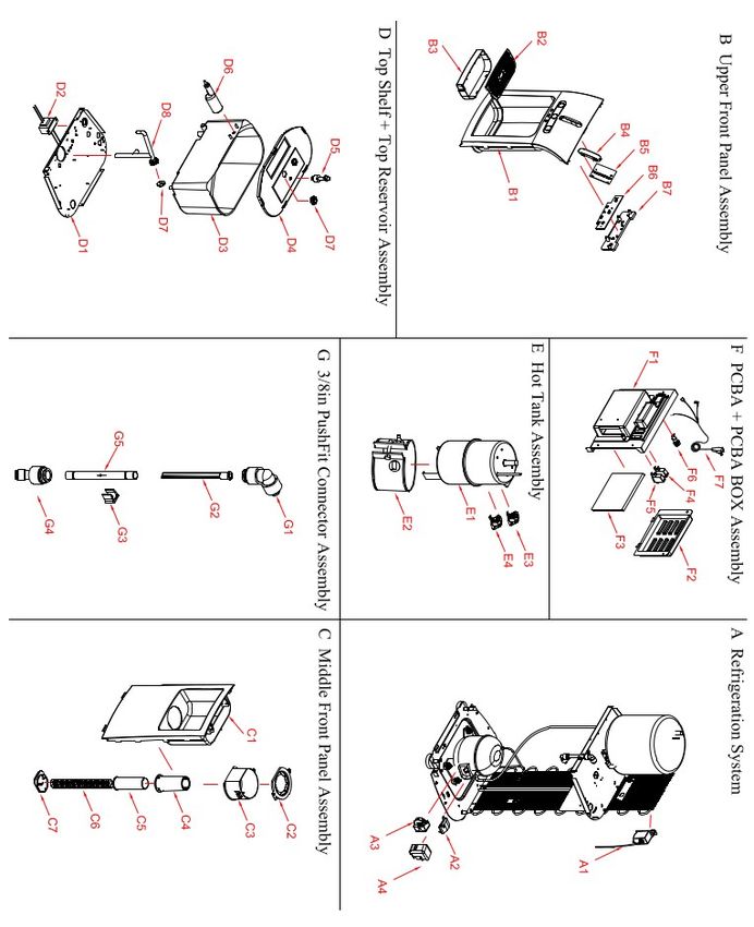
Notes

  2
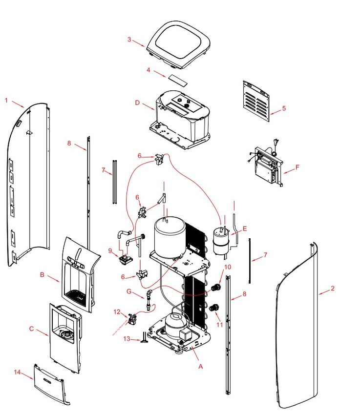
Table of Contents

Table of Contents                                           3
Notices and Safety Information                              4
Features and Benefits                                       5
Exploded Views and Parts List                               7
Installation                                                10
Operating Crystal Pro Water Dispenser                       14
Service and Maintenance                                     15
General Maintenance                                         15
Sanitizing Reservoirs                                       15
Draining Reservoirs                                         16
Resetting Leak Detection System                             18
Troubleshooting                                             19
Technical Specifications                                    20
Flow Diagram                                                21
Electrical Diagram                                          22
Warranty                                                    23

                                                3
Notices and Safety Information
Throughout this manual there are paragraphs set off by special headings.
“Notice” is used to emphasize installation, operation or maintenance information which is important, but
may not present a hazard to persons or property.
“Caution” is used when failure to follow directions could result in damage to equipment or property.
“Warning” is used to indicate a hazard which could cause injury or death if ignored.
The “Caution” and “Warning” paragraphs are not meant to cover all possible conditions and situations
that may occur. It must be understood that common sense, caution, and careful attention are conditions
which cannot be built into the equipment.
To ensure proper and efficient operation of the Crystal Pro Water Dispenser to your full satisfaction, carefully fol-
low the instructions in this manual.
Do not use with water that is microbiologically unsafe or of unknown quality without adequate disinfection be-
fore the system.
Check and follow the applicable plumbing codes and ordinances when installing this equipment. Local codes may
prohibit the discharge of acidic or caustic solutions to drain. An extra solution tank may be required to neutralize
the solution before discharging to drain. Follow local codes if they differ from this manual.
This dispenser has a maximum pressure rating of 80 psi (5.5 bar). A pressure regulator must be used for all instal-
lations. This will help prevent internal structural damage to the unit and potential water leaks. The pressure reg-
ulator should be installed on the water supply before the inlet connection.
Failure to use an appropriate anti-flood device for any reason will not obligate or make Crystal Moun-
tain responsible in any wayfor Product Liability issues relating to any claims, including water damage
claims.
Regularly inspect the filters, filter housings and the plumbing fittings and connections for water leaks. Water leaks
may cause damage to your office or facility and are not the responsibility of the manufacturer.
Only connect the power cord to a properly grounded outlet. NOTE: To provide additional protection from the risk
of shock, this unit MUST be connected to a ground fault circuit interrupter (GFCI) outlet at all times. Use of an ex-
tension cord will void any warranties.
Keep the power cord out of heavy traffic areas. To avoid a fire hazard, never put the power cord under rugs, near
radiators, stoves or heaters.
Do not use a damaged power cord or plug. If the power cord is damaged, a qualified service technician must re-
place it.
This dispenser is not intended for use by persons (including children) with reduced physical, sensory or mental
capabilities, or lack of experience and knowledge, unless they have been given supervision or instruction con-
cerning use of the dispenser by a person responsible for their safety. Children should be supervised to ensure
that they do not play with the dispenser.
This product should not be disposed with other household wastes. To prevent possible harm to the environment
or human health from uncontrolled waste disposal, recycle it responsibly to promote the sustainable reuse of ma-
terial resources. To recycle your used dispenser, contact your local recycler or waste collector for the proper proce-
dures.
Please Dispose of Properly
4Features & Benefits
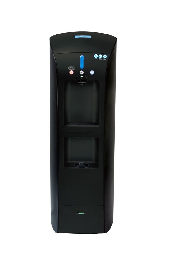
Thank you for purchasing the Crystal Mountain Crystal Pro Water Dispenser. The Crystal Pro brings a
fresh approach and a new look to point-of-use water dispensers. The system's contemporary color
scheme complements every office environment. There are no bottles to change and the supply is virtu-
ally unlimited.
Hot, Cold & Ambient Dispenser
Your Crystal Pro Water Dispenser will provide up to 0.3 gallons (1.2 L) of hot water from a stainless steel
reservoir using a 450 watt heating element. A bi-metal limiter is provided to prevent overheating and
can be manually reset. The hot water is factory pre-set to 181°F (83 °C). Cold water is chilled with a high
capacity compressor using R134 refrigerant. An electro-mechanical thermostat controls the tempera-
ture of the water in the one gallon (3.8 L) stainless steel reservoir. The cold water temperature is facto-
ry preset to a nominal 41°F (5 °C)
UV Light System
All models of the Crystal Pro dispensers are fitted with a UV-C band light system at the point of dispens-
ing and built into the ambient reservoir lid. This system is used to inhibit the growth of bacteria. When
dispensing Ambient or Cold water you will notice a pulsating “UV INSIDE” light which indicates the UV
light system activation.
Leak Detection System
All models of the Crystal Pro are fitted with a leak detector. This system will generate an audible alarm
and front panel light alert upon detecting water in the base of the unit. In addition, the system will au-
tomatically shut off the incoming water supply to prevent further damage.
Filtration System (not included)
Crystal Pro dispensers are designed to be used with reverse osmosis, or carbon filtration. For locations
where a drain is not present, a filtration-only option is recommended.
Internal Storage Reservoir
An internal storage reservoir eliminates the need for an external storage tank. The internal compart-
ment is large enough to contain most water treatment systems. A float mechanism guards against over-
flows.
Mechanical Components
All water connection fittings are compliant with NSF Standard 61. The Crystal Pro connects to the water
supply using a 1/4"female bulkhead fitting. The molded panels are made from recyclable ABS plastic.
5Features & Benefits
CR S P 3 K H K 1 C
Reservoir Type of lid No. of Temp.
Description Body color Lid color Voltage Any 1-2
Faucets Options
Alpha-
numeric
Characters
Crystal Pro S = Stainless P = POU 3=3 K=Black H=Hot, Cold K =Black 1 = 110v-115v C= Made
Steel Reservoir &Ambient in China
The Crystal Pro Water Dispensers come completely assembled and ready for set up and operation
either with, or without, installation of reverse osmosis or filtration cartridges.
Remove the dispenser from the box, saving the box and the packaging materials. The carton con-
tains the following items:
Qty Item
1 Crystal Pro Water Dispenser
1 M4 X 30 Tamper-proof Screw
1 M6 X 60 Expansion Bolt (220V units only – for CE compliance)
1 User Manual
Inspect the exterior for any damage which may have occurred during shipment.
1) To inspect the interior, remove the filtration service panel.
2) Visually inspect for any wires, tubing, or fittings which may have come loose during shipment.
3) Record the model and serial numbers below for future reference.
Record your Crystal Pro model number here:
Serial Number:
Date purchased:
Date installed:
Products offered and marketed by Crystal Mountain and its affiliates are protected by patents is-
6Parts Diagram
7Parts Diagram Detail
8Parts Listing
DESCRIPTION Part Number
1 Side Panel, Left SMT-C400002
2 Side Panel, Right SMT-C400003
3 Top Cover SUB-C400007
4 Lamp, Logo ELE-C100419
5 Cover, Back SMT-C400005
6 Solenoid, Low Pressure 24V DC (3 in unit) POU-C400001
7 Support Bracket, Rear Upper (2 in unit) SMT-C400008
8 Support Bracket, Front (2 in unit) SMT-C400007
9 Water Outlet PLC-C400015
10 Bulkhead Ftg, JG 1/4 x 1/4 POU-C000003
11 Bulkhead Ftg, JG 1/4 x 1/4 POU-C400012
12 Solenoid, High Pressure POU-C400002
13 Leak Detector Assy SUB-C400014
14 Panel, Lower Front SUB-C400035
A Refrigeration System N/A
A1 Cold Control REF-C400004
A2 Overload REF-C100300
A3 Relay REF-C100229
A4 Cover, Compressor PW2.5DV REF-C100301
B Upper Front Panel Assy SUB-C400033
B1 Upper Front Panel, Black N/A
B2 Grill, Drip Tray PLC-C400011
B3 Drip Tray Base PLC-C400009
B4 Cover, UV N/A
B5 PCB, UV Display N/A
B6 PCB, Push Button Module N/A
B7 Bracket, Push Button, Black N/A
C Middle Front Panel Assy, Black SUB-C400034
C1 Middle Front Panel, Black N/A
C2 Bracket, Cup PLC-C400007
C3 Door Lock PLC-C400008
C4 Cup Dispenser, Outer PLC-C400023
C5 Cup Dispenser, Inner PLC-C400024
C6 Spring, Cup Dispenser FAS-C400011
C7 Cup Dispenser Bottom PLC-C400022
D Top Shelf & Reservoir N/A
D1 Top Shelf SMT-C400013
D2 Transformer (120V/18V/1A) ELE-C400033
D3 Reservoir, Ambient PLC-C400001
D4 Lid, Reservoir PLC-C400002
D5 Float, Electronic ELE-C400026
D6 Float Valve, Mechanical POU-C400005
D7 UVC LED Module, 0.8W, 12-24 VDC ELE-C100401
D8 Water Outlet, SS, UV SMT-C100235
E Hot Tank Assy SUB-C400001
E1 Hot Tank, SS N/A
E2 Heater Band ELE-C100298
E3 Heat Limiter ELE-C100170
E4 Thermostat ELE-C100109
F PCB, Box & Cover Assy SUB-C400037
F1 PCB Box PLC-C400017
F2 Cover, PCB PLC-C400018
F3 Main PCB, UVC ELE-C100416
F4 Power Switch, Green ELE-C400007
F5 Power Switch, Red ELE-C400006
F6 Fuse, 10Amp ELE-C400032
F7 Power Cord ELE-C400029
G 3/8” Pushfit Connector Assembly N/A
G1 DM Elbow, 1/4 x 3/8(AEU0604), Gray POU-C100071
G2 In-Line, Screen Filter, 3/8 (70 Mesh) POU-C100063
G3 “C” Clip, 8mm, Plastic MIS-C100222
G4 Union, JG 3/8 x 1/4 POU-C100026
G5 Tube, SS, 9.5mm OD x 95mm SMT-C100220
Parts Not Shown
Adjustable Foot MIS-C400006
Filter Bracket SMT-C400006
9Installation
Position & Level
1) Locate the dispenser as close to the water supply and the electrical connections as possible.
2) Level the unit using the adjustable leveling feet and built-in level indicator.
3) Keep the dispenser at least 4 inches from the wall to ensure adequate airflow.
Warning: The dispenser should not be exposed to direct sunlight, heat sources, or an ambient air tem-
perature above 100°F (38°C) or below 37°F (3°C) or structural damage may occur.
4) To meet CE standards (if applicable), it is necessary to fasten the unit to the floor with an M6x60
expansion bolt.
A. Locate and drill a 43 mm deep hole using an alloy drill bit with 9 mm diameter.
B. Install the flat pad, the spring washer and the nut to the bolt, and then insert into the hole.
C. Remove the filtration service panel and locate the alignment hole on the base plate.
D. Align the dispenser with the expansion bolt using the hole in the base plate.
E. Using a wrench, secure the unit to the expansion bolt.
F. Reinstall the filtration service panel.
5) Your Crystal Pro Water Dispenser comes complete with a built-in cup holder under the water dis-
penser section. This holder is designed to hold up to twenty standard size cups with a diameter be-
tween 2.8"and 3.0" (71 – 76mm).
10Installation
Make Water & Electrical Connections
1) The dispenser contains push-to-connect type fittings on the rear of the unit for the water supply and
R/O drain. These fittings accept ¼"polypropylene plastic tubing. If copper tubing is to be used,
these fittings must be replaced with a metal design. In addition, drain ports are provided for
the hot and cold tanks.
2) Connect a potable, cold water supply to the unit. Pressure must be 40-80psi (2.8-5.5 bar) and
at a temperature no more than 105°F (41°C).
3) Flush the water supply feed until it runs clear before making connection to the dispenser.
Caution:
Installation should only be executed by trained personnel. Check and follow the applicable plumbing
codes and ordinances when installing this equipment. The connection must be to the potable mains wa-
ter supply and should be via a shut off valve. An Appropriate anti-flood device should be fitted as close-
ly as possible to the mains connection point. In order to meet plumbing regulations, a backflow pre-
venter may be required.
Failure to use an appropriate anti-flood device for any reason will not obligate or make Crystal Moun-
tain responsible in any way for Product Liability issues relating to any claims, including water damage
claims.
Do not connect the dispenser to a water line which exceeds 105°F (41°C) as structural damage
may occur.
This water dispenser has a maximum pressure rating of 80 psi (5.5 bar). A pressure regulator must be
used for all installations. This will prevent internal structural damage to the unit and potential water
leaks. This should be installed on the water supply before the dispenser water inlet.
4) Plug the dispenser into the wall outlet and verify that the green power status indicator is “on.” A fuse
located on the rear service panel helps to protect the internal circuits from damage.
Caution:
Damage to the dispenser will result if hot and cold switches are turned on without water inside the
tanks.
If the unit was placed on its side, it must stand upright for a minimum of twenty-four hours before op-
eration to allow the compressor to stabilize.
Install Filtration (if applicable)
The Crystal Pro is shipped from the factory with no internal filtration installed.
Consult with your filter supplier on the best filtration solutions for the local water conditions and follow
the manufacturer's instructions on their installation, use and servicing.
Flush Filters (if applicable)
All filters must be flushed prior to use per manufacturer's instructions. Depending upon your filtration or
R/O system, this process may be combined with the initial sanitizing process. It is recommended to flush
no less than two gallons through each filter. If using R/O, check to see if the filter manufacturer/supplier
recommends soaking the R/O membrane (the R/O filter system is sold separately), prior to installation.
Dispose of the first five gallons of product water.
11Installation
Sanitize the Dispenser
You must sanitize your system before using it for the first time. Failure to do so may result in poor water
taste and water quality. This is best accomplished as outlined below.
1) Ensure both water connections – supply and R/O drain (if applicable) are made at the rear of the
unit.
2) Open top service panel to gain access to the main storage tank.
3) Open the filtration service panel.
4) Place a sanitization cartridge (this can be an empty filter cartridge or one supplied by your filter sup-
plier – not supplied with unit) inline before the water inlet of the unit.
5) Using a small eyedropper, prepare the sanitization cartridge by adding two teaspoons of unscented,
liquid chlorine bleach.
6) Insert this cartridge inline prior to the system. If you have empty sanitization cartridges, install them
in the filter positions. If you do not, remove your filtration system, then bypass it with a ¼' polyeth-
ylene tubing and two - ¼" union quick connect fittings. Refer to the service manual of the filtration
system being used for proper sanitization of your filtration system.
7) Slowly turn on the water supply until the main storage tank is ½ full then turn off.
8) Carry out a visual inspection for any water leaks.
9) Lift the main storage tank lid taking care not to damage the float sensor or UV light.
10) Wearing sterile gloves, and using a clean, lint-free cloth thoroughly wipe down the inside of the main
storage tank with the bleach solution.
11) Let stand for ten minutes or until completely dry.
12) Slowly turn on the water supply.
13) Depress the dispensing buttons (alternate between hot, ambient and cold spigots) to allow the solu-
tion to run through the spigots and associated lines.
14) Drain the system until the chlorine bleach is no longer detected at the spigot. Drain the remaining
water through the drain connection at the rear of the unit.
15) Remove the sanitization cartridge and install the filter and/or R/O cartridges.
Note: Remember to connect the R/O drain line to the R/O cartridge. Ensure that the flow restric-
tor is visible inside the R/O drain line
Note: If R/O is being used, allow several hours to completely fill all tanks
The unit is supplied with a filter access door locking screw. This screw must be installed before
the unit is put into service.
12Installation
Turn on “Hot” & “Cold” Power Switches.
1) With all tanks completely filled with water, both the hot and cold switches at the rear of the dispenser
should be turned “on.” It will take approximately twenty minutes for the hot water and two hours
for the cold water to reach their temperature presets.
2) Record the service date on the inside filtration panel for future reference. This will ensure that
maintenance intervals are recorded and scheduled.
3) Reinstall the filtration service panel.
13Operating the Crystal Pro
Your Crystal Pro Water Dispenser contains a simple, intuitive user interface for operation and sta-
tus. Hot and Cold buttons are backlit and a nightlight is provided in the dispensing area.
Button/LED ON OFF Flashing
Power Indicator Dispenser Powered Dispenser Unpowered N/A
Hot Button Always On Dispenser Unpowered N/A
Ambient Button N/A N/A N/A
Cold Button Always On Dispenser Unpowered N/A
UV Activation Light UV System Ready* UV System Ready UV System Active
System Fault Indicator UV System Ready System Fault – i.e. Leak,
UV Bulb Needs Replacement
Short-Circuit
Night Light Dark Environment Light Conditions n/a
*On only when user is in front of the unit.
Note: To prevent the inadvertent dispensing of hot water, the dispense button must be held for 3 sec-
onds until a beep is heard. Press the button again for water to dispense
14Service & Maintenance
Once assembled, installed and flushed properly, your Crystal Pro Water Dispenser will provide
years of trouble-free operation. Installation and service should only be carried out by a trained
service professional. If applicable, filtration cartridges should be replaced every six months or as
directed by the manufacturer. The hot water tank may require periodic descaling of mineral
buildup inside the tank.
Service Notes
Caution:
Do not clean the water dispenser with a power washer or water jet device.
1) Sterile gloves must be worn when handling the filters, reservoir or any components that have
contact with the drinking water.
General Maintenance
1) Wipe all surfaces on the front panels, dispensing buttons, dispenser area, faucet, and drip
tray with an anti-bacterial cleaning wipe or spray.
2) Remove and clean the drip tray and grill. If the grill is damaged or heavily stained it should be
replaced.
3) Wipe away any dust which may have accumulated on the condenser grill.
4) Drain both tanks after long periods of non-use.
5) On R/O models periodically inspect the flow restrictor to ensure it is clean and unrestricted.
Caution:
Use only factory-authorized replacement parts. Using unauthorized parts or accessories may
cause damage or affect performance. Any damage, diminished performance or property dam-
age from using unauthorized parts or accessories is not covered under the manufacturer's war-
ranty.
Sanitize Reservoirs
1) All water reservoirs should be sanitized at regular intervals, especially after a long period of
non-use. This is best accomplished using a sanitization kit if available or by using the proce-
dure outlined below.
2) Prepare water dispenser for the service
3) Turn off both the hot and cold switches at the rear of the unit.
4) Unplug the electrical supply to the unit.
5) Turn off the water supply to the unit.
6) Drain all water storage tanks using the drain ports located at the rear of the dispenser.
15Service & Maintenance
Caution:
Take care to prevent burns when draining the hot tank.
7) Remove the existing filtration cartridges
8) Open the front panel to gain access to the filtration compartment.
9) Remove all cartridges from the filter compartment.
10) For R/O systems, ensure that the drain line with flow restrictor between the R/O cartridge and drain
port is removed first.
Install the Sanitization Cartridges
1) Place a sanitization cartridge (this can be an empty filter cartridge or one supplied by your filter sup-
plier – not supplied with dispenser) inline before the water inlet of the unit.
2) Using a small eyedropper, prepare the sanitization cartridge by adding two teaspoons of unscented,
liquid chlorine bleach.
3) Insert this cartridge inline prior to the system.
4) If you have empty sanitization cartridges install them in the remaining positions. If you do not, re-
move your filtration system, then bypass it with a ¼” polyethylene tubing and 2 - ¼" union quick con-
nect fittings. Refer to the service manual of the filtration system being used for proper sanitization of
your system.
5) Begin the sanitization process
6) Plug in the dispenser.
7) Slowly turn on the water supply.
8) Check for leaks or spills which may cause the leak detection system to activate.
9) Once all tanks are filled (approximately 3-5 minutes) let stand for 5-10 minutes.
10) Press and hold the hot, ambient and cold dispense buttons until water begins to flow.
11) Continue for 10 minutes, or until the bleach has been thoroughly flushed from the system.
Draining Reservoirs
1) Unplug the electrical supply to the unit.
2) Turn off the water supply to the dispenser.
3) Remove the cold drain plug on the rear to allow water to drain into a bucket.
4) Tilt the unit backward to facilitate draining of the water.
5) Repeat this process for the hot tank side.
6) Reinstall both drain plugs and verify they are secure.
16Service & Maintenance
7) Remove and replace cartridges
8) Remove all sanitization cartridges from the manifold or water inlet.
9) Turn water supply on and fill unit to flush remaining sanitizing agents then repeat steps 18-23
10) Install new filtration cartridges.
11) For R/O systems, ensure that the drain line is connected between the R/O cartridge and drain port.
Verify that the flow restrictor is properly installed.
12) Record the service date on the filtration panel.
13) Wipe down the base of the filtration compartment and reinstall the filtration panel.
14) Return the dispenser to service
15) Wipe down the drip tray and all outer panels.
16) Clean any dust and debris from the condenser grill.
UV System Replacement
1) Turn off the “hot” and “cold” switches on the rear of the dispenser.
2) Turn off the water supply and activate the dispensing buttons to relieve any pressure in the unit.
3) Unplug the electrical cord from the wall socket.
4) Remove the top panel to gain access to the UV assembly either on the reservoir lid or in the water
outlet tube. If replacing the UV on the reservoir lid, remove the lid from the reservoir.
Warning:
Do not remove the lamp from holder while illuminated and never look directly at the UV light as UV ra-
diation is dangerous for the eyes and skin
5) Unplug the UV wire connector.
6) Remove the old UV assembly by gently pulling the assembly out of the outlet tube or by unscrewing
the locknut if replacing the reservoir UV.
7) Install the new UV LED (Crystal Mountain part number ELE-C100401) by pushing into the outlet tube
or, if replacing the LED in the reservoir lid, by securing it in place with the locknut.
8) Re-attach the wire connector.
9) Plug the electrical cord into the wall socket.
10) Slowly turn on the water supply.
11) If the UV on the water outlet tube was replaced, activate the dispensing buttons and check that there
is no leak before installing the top panel.
12) Reinstall the top panel.
13) Turn on the “hot” and “cold” switches on the rear of the dispenser.
17Service & Maintenance
Reset Leak Detection System
All models of Crystal Pro Water Dispensers are equipped with a leak detection system. This system will
generate an audible and visual warning upon detecting water in the base of the unit. In addition, the sys-
tem will automatically shut off the incoming water supply valve to prevent further damage. The leak de-
tection warning will stop once the leak is stopped and the affected area is dried out.
Service notes
If an audible "click" is heard within 5 minutes of turning on the red power switch, the hot tank is likely
empty, and has overheated. The hot tank limiter will need to be reset.
Hot Tank On/Off Switch
Hot Tank Reset
Caution:
Turn off the hot tank and unplug the unit’s power cord before resetting the hot tank!
18Troubleshooting
Symptom Possible Cause Solution
No power to unit Check outlet and plug for proper connection
No Power / Power status indica- Check external circuit breaker/GFCI
tor off Circuit breaker or GFCI is tripped
Blown fuse Check fuse at rear of unit and replace if needed
Check external water supply valve
Tanks not filling during initial Fix source of leak
setup Remove source of blockage
Allow several hours for RO to fill
Power switches turned off Check the power switches on the rear panel
Water is not hot or cold
No, or low, flow from cold Water inside the cold tank frozen Turn off the cold switch for 4 hours to melt ice
inside tank
No, or low, flow from hot Hot tank needs to be descaled De-scale hot water tank
No, or low, flow from both hot Filter cartridges may need changed Change filter cartridge(s)
and cold Low pressure from water supply Check water supply pressure.
Hot tank limiter has tripped Reset the hot tank limiter.
Cold switch is off Check that the cold switch is “on” Check that the
Unit is not installed correctly unit is 4" from the wall, not in direct sunlight or in
Refrigeration Leak a room with high ambient temperature.
Sanitize the dispenser.
If the bad taste persists, taste the water coming
Unit not sanitized or Filters not flushed directly from the filter cartridge and change as
necessary. If still bad, change the filter, or con-
tact your service provider.
19Specifications
Water Dispenser
Failure to use an appropriate anti-flood device for any reason will not
obligate or make Crystal Mountain responsible in any way for Product
Safety Features
~1.0 KWH
20Flow Diagram
Anti-Flood Device
(not Supplied)
Ambient Storage Tank
Pressure Reducing Valve
(Not Supplied) w/ Mech Safety Float
Inlet UV Lamp
Hot Solenoid
Vent
Strainer
Filtration or R/O
System Hot Tank
Inlet Solenoid (Not Supplied)
Vent Drain
UV Lamp
R/O Drain (If Applicable) Dispenser Nozzle
(Bulkhead Supplied)
Ambient Solenoid
Cold Solenoid
Cold Water Reservoir
Drain
21Electric Diagram
W/W Link w/ Cook Solenoid
R/B Link w/ Inlet Solenoid
B/B Link w/ Cold Solenoid
R/R Link w/ Hot Solenoid
Logo Lamp
PCB UV Display
Link to Mid Shelf
Electric Ball
Float Valve
Leak Detection Line
PCB, Push Button Module
Leak Sensor Float Solenoid
Pushbutton
Hot Tank
Main PCBA
L Input fromFuse Transformer
UV Module LED UV
Limiter Hot/Cold Switch LED
UV Module Input Output
Thermostat Cold Control
To Relay
Cold Switch
Compressor
Heater To Overload
Hot Switch Fuse
L
N
L
Link with Top Shelf
Power Cord
22Crystal Mountain Two Year Limited Warranty
FIRST YEAR: GENERAL PROVISIONS AND EXCLU- FILTER AND RO MEMBRANE
SIONS: LIMITED WARRANTY
Crystal Mountain Products Inc promises the Subject to the conditions and limitations de-
original purchaser (user) to repair, or replace, This warranty is only applicable within the scribed below, Crystal Mountain warrants their
at Crystal Mountain’s discretion, any part of Continental Limits of the United States of filter cartridges to be free from defects in ma-
this water cooler which proves to be defective America and Canada. terial and workmanship at the time of installa-
in material or workmanship under normal use, This warranty will be voided if the serial num- tion, or six months from the date of purchase,
for a period of one year from the date of the ber is removed, defaced or obliterated. whichever comes first, when used within the
original purchase. During the first year of operating specifications listed in the filter
warranty, Crystal Mountain will provide parts, This warranty will be voided if parts to repair “Installation and Service Guide”.
at no charge, necessary to repair the product, the water cooler are not obtained from Crystal
provided that the water cooler has been in- Mountain. In addition all service to the sealed RO MEMBRANE WARRANTY
stalled and operated according to the manufac- refrigeration system must be performed by an Membranes carry a twelve (12) month pro-
turer’s written instructions. Failure to fol- authorized service agent or Crystal Mountain. rated warranty as follows: Credit 1/12th of the
low all instructions for operation and replacement cost for each unused month pro-
This warranty does not cover any inoperative
maintenance provided with this unit voids
components which occur as a result of liming, vided the system is installed and maintained
the warranty. according to factory instructions and the unit
scaling or other environmental conditions.
The hot tank casing is to be free from defects is operated within the specifications listed in
This warranty does not apply to any water the filter “Installation and Service Guide”.
in material and workmanship under normal use
cooler or components that become inoperable
for 2 years. This does not include electrical CONDITIONS OF FILTER WARRANTY
because of a failure to satisfy standards or
wiring and components.
regulations adopted by any government or The above warranty will not apply to the filters
If it becomes necessary to ship the inoperative agency thereof, subsequent to the date of ship- or RO membranes that are damaged because
water cooler to an authorized service center or ment from the factory. of neglect, misuse, alteration, accident, misap-
to Crystal Mountain, the user will be responsi- plication, physical damage, fouling and/or
Crystal Mountain will not be liable for
ble for shipping the product, prepaid, via com- scaling of membranes by minerals, bacterial
damage or wear to products caused by attack, sediment, or damage caused by fire,
mon carrier. Local delivery charges are not
abnormal operating conditions, accident, acts of God, freezing, or hot water.
covered.
abuse, misuse, unauthorized alteration or
The warranty does not cover charges to dis- repair, or if the products were not installed If the filters/membrane are altered by anyone
connect and reconnect plumbing and electrical in accordance with Crystal Mountain's other than Crystal Mountain the warranty is
printed installation and operating in- void. Crystal Mountain assumes no warranty
connections. In addition, the warranty does
liability in connection with the Reverse Osmo-
not cover the cost of diagnostic charges, in- structions, or for any damage caused
sis or Filtration system other than specified
cluding any problems with the sealed refriger- by hot water, freezing, flood, fire, or acts herein. Crystal Mountain will not be liable for
ation system. of God. any consequential damages of any kind or
WARNING nature due to use of Crystal Mountain prod-
SECOND YEAR:
ucts.
Crystal Mountain promises within the second Crystal Mountain hereby disclaims any
year to repair, or replace, at its discretion, any and all implied warranties including,
part of the sealed refrigeration system which is but not limited to, the implied warran-
ties of merchantability and fitness for
determined to be defective in material or a particular purpose. The manufacturer
workmanship. or its agents shall not be liable for con-
sequential damages, whether economic
If it becomes necessary to ship the defective
or otherwise, resulting from breach of
water cooler to an approved service center or this limited warranty. Failure to follow
to Crystal Mountain, the user will be responsi- all instructions for operation and mainte-
ble for shipping the product, prepaid, via com- nance provided with this unit voids the
mon carrier. Local delivery charges are not warranty.
covered.
The warranty does not cover charges to dis- The foregoing is in lieu of all other agreements
connect and reconnect plumbing and electrical expressed, implied or statutory and all other
connections. In addition, the warranty does obligations or liabilities of Crystal Mountain.
not cover the cost of diagnostic charges, in- Crystal Mountain does not assume or authorize
cluding any problems with the sealed refriger- any person to assume any obligations of liabil-
ation system. ity in connection with this product. In no
event will Crystal Mountain be liable for spe-
cial or consequential damages or for any delay
in the performance of this agreement due to
causes beyond their control.
23Crystal Mountain Products Inc.
US Office
1000 H Taylor Station Rd
Gahanna OH 43230
Tel: 614 454 1618
Fax: 614 866 7765
E-mail: sales@crystalcoolers.com
Crystal Mountain Products Limited
Canadian Office
200 Carnegie Dr Ste 234
St Albert AB T8N 5A7
Tel: 780 454 4545
Fax: 780 454 9816
E-mail: sales@crystalcoolers.com
European Office
Fence House,
Fence Avenue
Macclesfield, Cheshire United Kingdom SK10 1LT
Tel: +44(0) 1625 439 111
Fax: +44 (0) 1625 502 527
E-mail: cmeurope@crystalcoolers.com
Crystal Mountain International Limited
Hong Kong Office
Room 610, Winfield Commercial Building
6-8a Prat Avenue, Tsimshatsui
Kowloon, Hong Kong Tel: (852) 2368 1989
Fax: (852) 3017 6727
E-mail: cmasia@crystalcoolers.com
DOC-C400001 Rev.042920
24You can also read