D2.7B - Draft of schedules for BAT and BREF in Cement, Glass, Non-ferrous
←
→
Page content transcription
If your browser does not render page correctly, please read the page content below
SILC I
           Sustainable Industry Low Carbon scheme
                67/G/ENT/CIP/13/D/N03S02

    D2.7B - Draft of schedules for BAT and
     BREF in Cement, Glass, Non-ferrous

Internal document
                       D.2.7 B
code:
Version:               FINAL
Date:                  31/12/2014
Status:                Approved
Dissemination level:         CO               PP                RE               CO
                                          Limited to      Reserved to a     Confidential,
                           Public           project      specific partner      project
                                         stakeholders         group         partners only
                                                                                  V
Author:                D.Forni
                       Waste Heat Valorisation for More Sustainable Energy Intensive
Project:
                       IndustrieS
Acronym:               WHAVES
Code:                  SI2.666133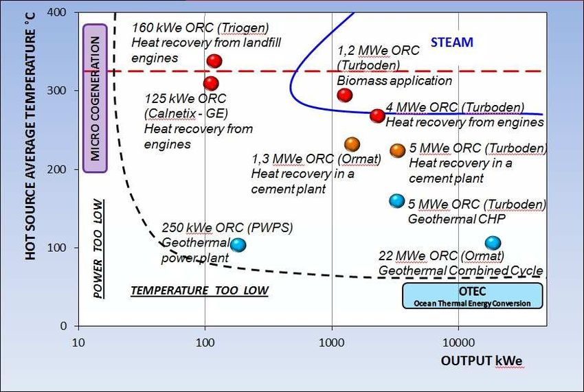
Energy Efficiency BREF

List of content:

       1.   Introduction
       2.   Analysis of the current BREF document
       3.   Relieved discrepancies to be revised about “COGENERATION”
       4.   The ORC technology
                 Description
                 Achieved environmental benefits
                 Cross media effects
                 Operational data
                 Applicability
                 Economics
                 Driving force for implementation
                 Examples
                 Reference literature

                                             2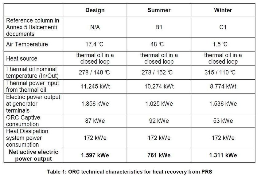
1. Introduction
        According to recent case studies and advance in literature and in technology, it results
important to underline how the increased available choices in the field of COGENERATION and
HEAT RECOVERY should lead to a review of some information included in the current version
of the BREF document for “ENERGY EFFICIENCY”.
Furthermore, the availability of new approaches and tools for the preliminary evaluation for
selecting an effective cogeneration technology should be also remarked.

2. Analysis of the current BREF document
       After a carefully analysis of the BREF document: “Reference Document on Best Available
Techniques for ENERGY EFFICIENCY in the BREF CEMENT” issued on February 2009, it is
suggested to modify the following preliminary points:
       1. HEAT RECOVERY is mentioned at point 3.3, but the associated techniques are limited
           to the application of Heat exchangers and Heat pumps or of Chillers and cooling
           systems. As a consequence this section of the BREF results not complete and up to
           date.
       2. COGENERATION techniques are indicated in BAT n. 20 as measures for improving
           energy efficiency, stating that “Cogeneration opportunities should be sought on the
           identification of possibilities, on investment either on the generator's side or potential
           customer's side, identification of potential partners or by changes in economic
           circumstances (heat, fuel prices, etc.)”.
       3. COGENERATION techniques are indicated in Chapter 3 as “Techniques to consider
           for achieving energy efficiency in energy-using”, at point 3.4 – Cogeneration, where
           only some of the applicable techniques are described.
           Furthermore, at point 3.4.1 some information is missing or should be more exhaustive
           on nowadays known and already applied techniques, such as Organic Rankine Cycle
           (ORC) turbogenerator.

3. Relieved discrepancies to be revised about “HEAT RECOVERY” and
   “COGENERATION”
       In the following paragraph are presented information and data in the current BREF together
with new and more detailed elements that should be considered when reviewing the BREF
document.

NOTE on “HEAT RECOVERY” and “COGENERATION”
Neither in § 3.3 “Heat Recovery” nor in § 3.4 “Cogeneration” it is explained the role of “Heat-
recovery equipment” in terms of energy efficiency.
Heat-recovery equipment in CHP systems is used to capture thermal energy rejected from prime
movers and other heating sources and to make the recovered heat available for useful purposes.

The 2012/27/EU Directive on Energy Efficiency, in chapter III “efficiency in energy supply”, art.
5.c requires a cost benefit analysis when “an industrial installation with a total thermal input
exceeding 20MW generating waste heat at a useful temperature level is planned or substantially
refurbished, in order to assess the cost and benefits of utilising the waste heat to satisfy
economically justified demand, including through cogeneration, and of the connection of that
installation to a district heating and cooling network”.

                                                 3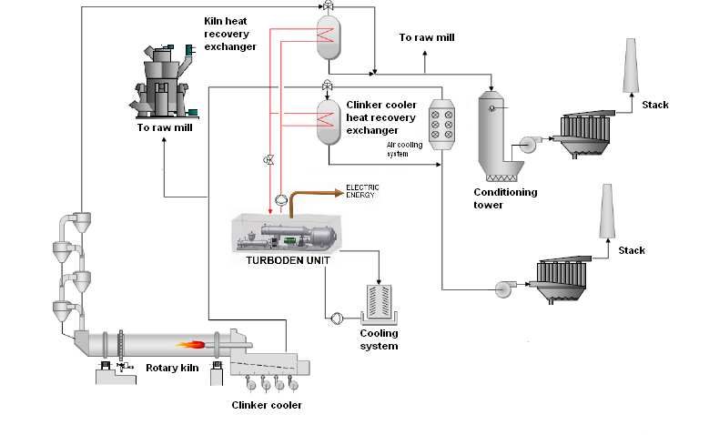
Anyway there was the possibility for Member States to notify exemptions and a number of
Member States did it. Moreover the waste heat recovery for electricity generation is not considered
cogeneration so far. Thus this measure risks not to be considered in the cost benefit analysis.
NOTE: in the current BREF document the ORC systems are listed only in the COGENERATION.
As a consequence, all the related notes are mainly linked to the section of the Cogeneration in the
current structure of the BREF, but should be also considered in the revision of the section on heat
recovery.
§ 3.4.1 – Cogeneration (See page 181)
a) At page 181, in Table 3.20 (List of cogeneration technologies and default power heat ratios
[146, EC, 2004]) the values for some technologies are missing.
In particular, the table should be corrected as follows:
- “Organic Rankin cycles” is to correct with “Organic Rankine Cycles”;
b) At page 181, after the above mentioned Table 3.20, it is stated that: “The annual load
versus time curve can be used to determine the selection and size of a CHP”.
It should be added:
“In case of Heat Recovery with ORC technologies, it is actually proved that other and dedicated
evaluation tools can be also used.
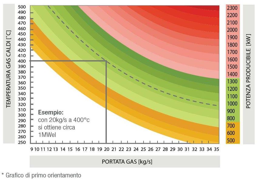
For example, the diagram reported in Figure 1 developed in the H-REII project (ref.: LIFE08
ENV/IT/000422). This tool (a.k.a. preliminary heat recovery analysis diagram) allows easily
determining the needed quantities of mass flow rate (kg/s) and temperature (°C) for producing a
desired amount of power (kW).”
4
Temperature [°C]                                                     Potential power [kW]

            Example
            with a mass flow of 20
            kg/s at 400°C can be
            produced 1 MW

                                     Mass flow [kg/s]

Figure 1 Preliminary heat recovery analysis diagram

    c)   From page 182 to page 189, some different types of cogeneration power plant are
         described. According to the advances in terms of industrial installations, achieved benefits
         and economical profitability, it should be added in the BREF document also a specific sub-
         section on the ORC turbogenerators.

The characteristics and typical technical data of this generation technology are reported in the
point “4. The ORC Technology”, where there are all the information usually present in the BREF
documents (Description, Achieved environmental benefits, Cross-media effects, Operational data,
Applicability, Economics, Driving force for implementation, Examples).

                                                        5
4. The ORC technology

Description
         In a typical Organic Rankine Cycle (ORC) based heat recovery system, the heat contained
in the waste exhaust gas is transferred indirectly -via a thermal oil circuit- or directly to the organic
fluid running the Rankine cycle.
The ORC plant produces electricity and low-temperature heat through a closed thermodynamic
cycle which follows the principle of the Rankine cycle.
In an ORC generator the organic fluid running the closed cycle (Figure 2) is pre-heated (2-7) in a
regenerator, then vaporized (7-4) through heat exchange with the hot source. The generated vapour
is expanded (7-5) in a turbine that drives an electricity generator. Leaving the turbine, the organic
working medium (still in the vapour phase) passes through the re-generator (5-6) transferring heat
to the organic liquid before vaporizing, therefore, increasing the electric efficiency through internal
heat recovery. The organic vapour then condenses (6-1)) delivering heat to the cooling water
circuit. After the condenser, the working medium is brought back to the pressure level required
(for turbine operation) by the working fluid pump and then starts again the cycle.
The low-temperature heat is normally discharged to a thermal user or to the atmosphere through air
cooled radiators inserted in a closed cooling water circuit (evaporative cooling towers can also be
employed). If there is a demand for low temperature heat, it is possible to design the cycle in order
to condense at higher temperature and feed in to the user (e.g. heating, district heating, etc.).

The operation of the ORC plant is fully automatic in normal operating conditions as well as in shut
down procedures without any need of supervision personnel. In case of faulty conditions, the ORC
plant will be switched off automatically and separated from the thermal oil circuit and from the
electrical grid.
The ORC module is designed to automatically adjust itself to the actual operating conditions:
variations on exhaust gas temperatures and flows (in reasonable span times) will not affect the
functionality of the system (but just the power output).
When compared to alternative technologies of comparable sizes (from 0.2 to 3 MW of electric
production), ORC plants demonstrate the following advantages:
o Very high turbine efficiency (up to 85 %)
o Low mechanical stress of the turbine, due to the low peripheral speed
o Low RPM of the turbine allowing the direct drive of the electric generator without reduction gear
o No erosion of blades, due to the absence of moisture in the vapour nozzles
o High cycle efficiency also at partial load
o Long life
The technology shows many other advantages, such as simple start-stop procedures, quiet
operation, minimum maintenance requirements, good performances at partial load (it is possible to
operate the cycle down to 10 % of the nominal load without incurring in any problem).
The ORC modules can be operated with good efficiency at partial load by simply changing the
feeding conditions (thermal oil flow or temperature). The ORC plants can, without any problems,
be automatically operated with values that differ from the nominal values for the thermal oil and
hot water temperatures. The operation of the plant either with higher hot water outlet temperatures
or lower thermal oil inlet temperatures leads to a decrease of the electric efficiency and therefore to
less electricity generation of the ORC plant.

                                                   6
Figure 2 Basis configuration of an ORC turbogenerator (left) and its representation (right)in a T-s
   diagram

Achieved environmental benefits
        The electricity is generated using the recovered waste heat, thus without any additional
consumption of fuel nor additional emissions. Moreover the electricity is usually self consumed
inside the plant itself, thus avoiding also the grid losses. The avoided emissions depend on the
national emissions for electricity generation.

Cross-media effects
        Besides the lower usage of electricity and, if also heat is recovered after or before the ORC,
fossil, with the related reduction of CO2 emissions, there is a consequent reduction of energy costs
and. an increase of competitiveness. When the recovered waste heat feeds a district heating
network, the installation of an ORC can increase the convenience of the investment, since it
increases the load factor of the heat exchanger, one of the most expansive elements of the system.

Operational data
        The operational data depend on the field of application (process), and on the size of the
ORC.
Usually, the technical parameters to be considered are: thermal energy waste state (fluid/gas), mass
flow (kg/hour), inlet and outlet temperatures (°C), working hours (hours), type of process (steady
or batch).
Other parameters are important in case of refining the investigation of the achievable
performances.
An example of ORC technical characteristics applied in cement industry is reported in Figure 2.

                                                      7
Figure 2 – ORC technical characteristics for heat recovery from PRS

Applicability
        The organic Rankine cycle (ORC) turbogenerator is an effective power plant for
decentralized small- to medium-scale energy applications, for an electric power output ranging,
currently, from approximately 50 kWe up to about 5 MWe (Figure 3).
The most relevant applications of ORC plant in industrial heat recovery are actually represented by
energy intensive processes as: Steel, Cement and Glass (see examples).

Figure 3 Input temperature and output power ranges of commercially available ORC systems. (source [6])

Economics
        The economic viability of such systems is critically dependent on the costs of installation
and maintenance costs and on the cost of electricity bought from the grid. Due to its high specific
investment cost, a careful design of the ORC system is needed in order to define the best sizes of
all equipment installed.

                                                     8
Furthermore, the advantages of some energy intensive industrial processes (Steel, Cement, Glass)
have already been studied and quantified ([4] and [5]).
It is also interesting to evaluate the synergies of heat recovery for external thermal needs (district
heating or other factories) and for electricity generation ([7]).

Driving force for implementation
        If there is no internal use of the recoverable thermal energy otherwise dispersed in the
environment, the electricity generation is a viable solution to exploit this free resource. The
electricity generated is usually self consumed in the plant itself lowering the electricity purchased
from the grid and enhancing the energy efficiency of the plant and the profit.

Examples in Europe
Beyond the examples in the table below, there are a number of plants in advanced stage of
construction or just commissioned around Europe.

Year            Sector                          Site                                   ORC            ORC gross
                                                                                       Manufacturer   power [MW]
1999            Cement                          Heidelberg Zement, Germany             Ormat              1.5
2012            Cement                          Holcim Romania                         Turboden            4
2013            Cement                          Jura Cement, Switzerland               ABB                 2
2014            Cement                          Holcim Slovakia                        Turboden            5
2011            Glass                           Vetrerie Sangalli Manfredonia, Italy   Ormat              2.0.
2012            Glass                           AGC Cuneo, Italy                       Turboden           1.3
2013            Steel                           ESF Riesa, Germany                     Turboden           2,7
2014            Steel                           ABS Pozzuolo del Friuli, Italy         Exergy             1,2

Reference literature
   [1] D. Chinese, A. Meneghetti, G. Nardin, Diffused Introduction of Organic Rankine Cycle for
       Biomass-based Power Generation in an Industrial District: a Systems Analysis, Int. J.
       Energy Res., 28, 1003-1021, 2004.
   [2] G. Angelino, M. Gaia, E. Macchi, A Review of Italian Activity in the Field of Organic
       Rankine Cycles, Proceedings of the Intl.VDI Seminar (Verein Deutsche Ingenieure),
       Bulletin 539, VDI-Düsseldorf, 465-482, 1984.
   [3] S. Quoilin, V. Lemort, Technological and Economical Survey of Organic Rankine Cycle
       Systems , Proceedings of European Conference on Economics and Management of Energy
       in Industry. Vilamoura, Portugal, 2009.
   [4] J. A. Moya, N. Pardo, A. Mercier , The potential for improvements in energy efficiency
       and CO2 emissions in the EU27 cement industry and the relationship with the capital
       budgeting decision criteria, Journal of Cleaner Production 19 (2011).
   [5] D. Forni, N. Rossetti, V. Vaccari, M. Baresi, D. Di Santo, Heat recovery for electricity
       generation in Industry, Proceedings of ECEEE summer industrial study 2012.
   [6] HREII project, Life EU programme http://www.hreii.eu/
   [7] D. Forni, F. Campana, Innovative system for electricity generation from waste heat
       recovery, Proceedings of ECEEE summer industrial study 2014.

                                                   9
Cement, lime and magnesium oxide BREF

List of content

       1.  Analysis of the current BREF document
       2.  Relieved discrepancies to be revised about the “COGENERATION” in the
       CEMENT industries
           § 1.2.5.8 – Cogeneration
           § 1.4.2.4 - Energy recovery from kilns and coolers/cogeneration
           § 4.2.3.2 - Cogeneration with Organic Rankine Cycle (ORC) process

                                          10
2. Analysis of the current BREF document
“Best Available Techniques (BAT) Reference Document for the Production of CEMENT,
LIME and MAGNESIUM OXIDE” Industrial Emissions Directive 2010/75/EU
(Integrated Pollution Prevention and Control) (April 2013)”
After a carefully analysis of the BREF document: “Best Available Techniques (BAT)
Reference Document for the Production of CEMENT, LIME and MAGNESIUM OXIDE”
issued on April 2013, it is necessary to fix the following preliminary points:
1. the HEAT RECOVERY is mentioned in all the three industries as BAT for the
reduction of the energy consumption for thermal needs:
- for CEMENT industries, see:
§ 1.2.5.7.1.2 Planetary (or satellite) coolers
§ 1.2.5.8 Cogeneration
§ 1.4.2.4 Energy recovery from kilns and coolers/cogeneration
§ 6.2.3 Cement manufacturing – cogeneration/recovery of excess heat
see BAT n. 7, point b) and BAT n. 9 (ref.: § 4.2.3.2, pages 343-344);
- for LIME industries, see:
§ 2.2.7.6 Rotary kilns with preheaters (PRK)
see BAT n. 33, point a) (ref.: § 4.3.3, page 357);
- for MAGNESIUM OXIDE industries,
§ 3.4.3 Reduction of energy consumption (energy efficiency)
see BAT n. 56, point a) (ref.: § 4.4.2, page 370);
2. the HEAT RECOVERY techniques to be adopted are then widely described ONLY in
the CEMENT industries, while for LIME and MAGNESIUM OXIDE industries the
description is quite limited (probably, due to a not significant profitability in the costs-
benefits analysis).
- for CEMENT industries, see § 1.4.2.4, page 107;
- for LIME industries, see § 2.4.2 – Table 2.34, page 252;
- for MAGNESIUM OXIDE industries, see § 3.4.3, page 319;
113. COGENERATION techniques are indicated in BAT n. 9 as measures for reaching the
overall reduction of the energy consumption thanks to the use of energy (thermal and
electric) recovery systems.
4. Furthermore, the reported information and the data about the use of electricity
generation processes for energy recovery in cement manufacturing need for AN
IMPORTANT REVISION. This techniques is very diffused outside Europe, adopted in
over 700 plants in China and in around 850 plants worldwide. In Europe the number of
plants with heat recovery for electricity generation based on ORC is increasing, due to
the characteristics of the European plants and to the enhanced operational performances
and the economical profitability of the ORC solution. As a consequence the application
of heat recovery for electricity generation via ORC in the cement industries needs new
and more detailed reference elements to be added in the related BREF document.
123. Relieved discrepancies to be revised about the “COGENERATION” in the CEMENT
industries
In the following lines, the information and data in the current BREF document are
implemented or compared with the investigated new and more detailed elements that should be
mentioned in a BREF document review.
§ 1.2.5.8 – Cogeneration (See page 38)
Current version Reviewed version
“ For the first time in a German cement kiln, “Since its first application in the cement kiln of
the Organic Rankine Cycle (ORC) process for Lengfurt (Germany), the Organic Rankine
the cogeneration from low temperature waste Cycle (ORC) process for the cogeneration from
heat has been applied.” low temperature waste heat is now evaluated
and applied in various new cement plants.
Nowadays, the Organic Rankine Cycle (ORC)
turbogenerator is an effective power plant for
decentralized small- to medium-scale energy
applications, for an electric power output
ranging, from approximately 500 kWe up to
about 10 MWe.”
“The results available from the German cement “The results available from the ORC
plant indicate that 1,1 MW electrical power can turbogenerators that started operations in
be generated with the given mode of 2012-2014 in the cement plants of Alesd
operation.” (Romania) 4 MWe, Wildegg (Switzerland)
2MWe and Rohožník (Slovakia) 5 MWe,
indicate that up to 5 MW electrical power can
be generated with the given mode operation.”
“Moreover the 1,5 MWe ORC turbogenerator
installed in 2010 at the cement plant of Ait Baha
(Morocco) shows the applicability and
13reliability of this solution also for warmer climatic conditions”. 14
§ 1.4.2.4 - Energy recovery from kilns and coolers/cogeneration (see page 107)

Description
The amendment proposal is:
“In general, the principle behind all the processes of combined heat and power (or
“cogeneration”) is the use of the heat otherwise dispersed by a system generating electricity only.
On the other hand, many industrial applications eject heat with characteristics not suitable for
traditional steam cycles. Steam cycles don’t allow a profitable conversion in electricity of heat in
middle-temperatures range.
In the cement industry, the diffusion of ORC turbogenerators is reflecting the increased interest in
this solution thanks to higher performances in terms of electrical power generation from low
temperature exhaust gases and lower manage and maintenance duties.”

Achieved environmental benefits
The addendum proposal is:
“the benefits from the ORC processes - in terms of CO2 emissions and reduction in the
consumption of primary energy - for the EU27 cement industry have been quantified thanks to the
H-REII project (H-REII project, co-financed by the Life+ programme of EU – ref.: LIFE08
ENV/IT/000422) activities, as follows:
                     Potential production of Electric power by ORC processes

                     Figure 1 Potential production of Electric power by ORC processes

                                                   15
Related achieved CO2 emissions in EU27
Figure 2 Related achieved CO2 emissions
Cross media effects
No changes.
Operational data
The amendment proposal is:
“Nowadays, the available technologies allow increased performances of using an ORC
turbogenerator in cement manufacturing:
Ait Baha (Morocco) Plant, 2010:
heat recovery from the KILN EXHAUST GAS.
Intermediate thermal oil loop to transfer HEAT to the ORC cycle;
Condensating HEAT dissipated through intermediate water cooling loop and dry-air cooling
system.
Heat source: exhaust gas at 330°C
Gas cooled down to 220°C (extra heat used for raw material pre heating)
ORC electric power: ca. 2 MWe”
16Alesd (Romania) Plant, 2012:
heat recovery from the KILN EXHAUST GAS with intermediate thermal oil loop and from the
CLINKER COOLER AIR with a second loop of pressurised water to transfer HEAT to the ORC
cycle;
Condensating HEAT dissipated through intermediate water cooling loop and wet cooling towers.
Clinker production capacity: ≈ 4.000 ton/day
Heat source: exhaust gas @ 360°C (PRS) and 250 °C (C C)
Thermal oil (PRS) and pressurised water (CC) heat recovery loops
ORC electric power: ca. 4 MWe”
Rohožník (Slovakia) Plant, 2013:
Heat recovery from the KILN EXHAUST GAS with intermediate thermal oil loop and from the
CLINKER COOLER AIR with a second loop of pressurised water to transfer HEAT to the ORC
cycle;
Condensating HEAT dissipated through intermediate water cooling loop and wet cooling towers.
Clinker production capacity: ≈ 3.600 ton/day
Heat source: exhaust gas @ 360°C (PRS) and 310 °C (C C)
Two thermal oil heat recovery loops
ORC electric power: ca. 4 MWe”
Applicability
No changes.
Economics
The amendment proposal is:
“Nowadays, according to the increased sizes with higher performances of the current ORC
turbogenerators and to the increasing energy costs, the Business Plan in cement manufacturing
are a more attractive and profitable and can be sustainable also without incentives. The Heat
recovery with its related electric power self-production leads to an increased competitiveness due
to the lower costs of electric power used in the processes for producing the same quantities of
cement.
The exploitation of recovered heat for external use (e.g. district heating/cooling) and for electricity
generation are not necessarily alternative options, but can be synergic and can make more
17attractive the Business Plan, even if the investment is higher. This is due to the higher utilization of
the heat exchanger, one of the most costly components of the system.
Furthermore, the presence of heat recovery plants that produce power with no emission and fuel
consumption implies economic benefits also for the grid: reduction of distribution losses,
stabilization of grid load and reduction of blackouts frequency.”
Driving force for implementation
No changes.
Example plants
In the current version of the BREF, the other mentioned examples are not distinguishing between
the plants with conventional steam cycle and the ones with ORC process.
Furthermore, it results that the Lengfurt cement plant is the one and only applying an ORC
solution and that its choice seems mainly due to the funding by German government.
The amendment proposal is:
“there are other cement plants applying energy recovery by means of an ORC turbogenerator:
- Ait Baha in Morocco: Cement plant with installed an ORC turbogenerator, size
1.5MWe for heat recovery (started up in 2010);
- Bihor in Romania: Cement plant with installed an ORC turbogenerator, size 4MWe
for heat recovery (started up in 2012);
- Rohožník in Slovakia: Cement plant with installed an ORC turbogenerator, size
5MWe for heat recovery (started up in 2014).
Reference literature
See the end of next section.
18-
§ 6.2.3.2 - Cogeneration with Organic Rankine Cycle (ORC) process (see page 419)
It should be added a sub-paragraph on:
Working principle
The heat contained in the exhaust gas is transferred indirectly -via a thermal oil circuit- or directly
to the ORC plant.
The ORC plant produces electricity and low-temperature heat through a closed thermodynamic
cycle which follows the principle of the Organic Rankine Cycle (ORC).
In the ORC process, designed as a closed cycle, the organic working medium is pre-heated in a
regenerator and in a pre-heater, then vaporized through heat exchange with the hot source. The
generated vapour is expanded in a turbine that drives an electric generator. Leaving the turbine,
the organic working medium (still in the vapour phase) passes through the regenerator that is used
to pre-heat the organic liquid before vaporizing, therefore, increasing the electric efficiency
through internal heat recovery. The organic vapour then condenses and delivers heat to the
cooling water circuit. After the condenser, the working medium is brought back to the pressure
level required (for turbine operation) by the working fluid pump and then preheated by internal
heat exchange in the regenerator.
The low-temperature heat is provided to a thermal user or discharged to the atmosphere through
air cooled radiators inserted in a closed cooling water circuit (evaporative cooling towers can
also be employed).
The operation of the ORC plant is fully automatic in normal operating conditions as well as in
shut down procedures without any need of supervision personnel. In case of faulty conditions, the
ORC plant will be switched off automatically and separated from the thermal oil circuit and from
the electrical grid.
The ORC module is designed to automatically adjust itself to the actual operating conditions:
variations on exhaust gas temperatures and flows (in reasonable span times) will not affect the
functionality of the system (but just the power output).
19Description of a cement plant with ORC Based Heat recovery System
The use of an-organic fluid enables efficient use of a lower temperature thermal source stream as
exists in cement production processes, to produce electricity. The ORC operates automatically
requiring minimal supervision and maintenance, and can be configured for no water consumption.
Thermal energy contained in the two main waste heat stream – Kiln gas after pre-heating cyclones
and Clinker cooler air – is captured by waste heat oil heaters ( WHOH ), and transferred to the
ORC turbogenerator using a closed loop thermal oil sub-system ( Ref. Figure 3 ). The location of
the WHOHs depends on specific plants related factors and is defined in concert with plant
operators and referenced suppliers with the aim of:
• Not affecting the optimum cement production operation,
• Minimizing effects on existing equipment (mills, fans, filters, etc. ).
• Guaranteeing reliable and durable operations,
• Minimizing investment cost.
The ORC turbogenerator accepts the hot thermal oil generated in the WHOHs and converts
approximately 20% of the input thermal power into electric power.
The balance of this thermal power is removed from the cycle by a closed loop cooling sub-system
that typically dissipates it to the environment.
The electrical power can be delivered to the grid or used to feed the cement plant internal electric
loads.
As alternatives to thermal oil heat recovery systems, either pressurized water or saturated steam
solutions can be adopted to extract heat from the hot gas and transfer heat to the ORC plants.
As an indication, the power that can be produced by an ORC system in a typical cement making
process can range from 0.5 to 1.5 MW/ Thousand metric tons per day of Clinker production
capacity ( assuming heat recovery from Both kiln and cooler waste flows ).
Using this figure, it can be estimated that the energy produced by an ORC can account for around
10 – 20% of the total electricity consumed by a cement plant.
20ORC Unit
Figure 3 Example of ORC based Heat Recovery System in a cement plant.
The application of ORC turbogenerators in cement plant in Ait Baha, Morocco (2010) has the
following characteristics:
Heat recovery from the KILN EXHAUST GAS.
Intermediate thermal oil loop to transfer HEAT to the ORC cycle;
Condensating HEAT dissipated through intermediate water cooling loop and dry-air cooling
system.
Heat source: exhaust gas at 330°C
Gas cooled down to 220°C (extra heat used for raw material pre heating)
ORC electric power: ca. 2 MWe”
The application of ORC turbogenerators in cement plant in Alesd, Romania (2012) has the
following characteristics:
Heat recovery from the KILN EXHAUST GAS with intermediate thermal oil loop and from the
CLINKER COOLER AIR with a second loop of pressurised water to transfer HEAT to the ORC
cycle;
Condensating HEAT dissipated through intermediate water cooling loop and wet cooling towers.
21Clinker production capacity: ≈ 4.000 ton/day
Heat source: exhaust gas @ 360°C (PRS) and 250 °C (C C)
Thermal oil (PRS) and pressurised water (CC) heat recovery loops
ORC electric power: ca. 4 MWe”
The application of ORC turbogenerators in cement plant in Rohožník, Slovakia (2014) has the
following characteristics:
Heat recovery from the KILN EXHAUST GAS with intermediate thermal oil loop and from the
CLINKER COOLER AIR with a second loop of pressurised water to transfer HEAT to the ORC
cycle;
Condensating HEAT dissipated through intermediate water cooling loop and wet cooling towers.
Clinker production capacity: ≈ 3.600 ton/day
Heat source: exhaust gas @ 360°C (PRS) and 310 °C (C C)
Two thermal oil heat recovery loops
ORC electric power: ca. 4 MWe”
Reference literature
- VV.AA. Waste heat recovery in the cement sector: market and supplier analysis, 2014
- D. Chinese, A. Meneghetti, G. Nardin, Diffused Introduction of Organic Rankine Cycle for
Biomass-based Power Generation in an Industrial District: a Systems Analysis, Int. J. Energy
Res., 28, 1003-1021, 2004.
- G. Angelino, M. Gaia, E. Macchi, A Review of Italian Activity in the Field of Organic Rankine
Cycles, Proceedings of the Intl.VDI Seminar (Verein Deutsche Ingenieure), Bulletin 539, VDI-
Düsseldorf, 465-482, 1984.
- S. Quoilin, V. Lemort, Technological and Economical Survey of Organic Rankine Cycle
Systems , Proceedings of European Conference on Economics and Management of Energy in
Industry. Vilamoura, Portugal, 2009.
- J. A. Moya, N. Pardo, A. Mercier , The potential for improvements in energy efficiency and
CO2 emissions in the EU27 cement industry and the relationship with the capital budgeting
decision criteria, Journal of Cleaner Production 19 (2011).
- R. Vescovo, Waste heat into power, Waste heat generation August 2011.
- D. Forni, F. Campana, Innovative system for electricity generation from waste heat recovery,
Proceedings of ECEEE summer industrial study 2014.
22Non ferrous metal BREF
List of content
Introduction
1. Addendum proposal
2. Waste heat recovery
3 Electricity generation from waste heat
4. Organic Rankine Cycle
5. ORC-based energy recover systems
a. Heat recovery from ferro-alloys submerged arc furnaces
Operational data
Feasibility studies
heat recovery in a silicon metal plant
heat recovery in a ferro-manganese plant
b. Heat recovery in the Copper Industry
Operational data
Feasibility studies
heat recovery in a primary copper smelter
heat recovery in a copper rolling mill
Relieved discrepancies to be revised about the “COGENERATION” in the CEMENT
industries
§ 1.2.5.8 – Cogeneration
§ 1.4.2.4 - Energy recovery from kilns and coolers/cogeneration
§ 4.2.3.2 - Cogeneration with Organic Rankine Cycle (ORC) process
23INTRODUCTION
Heat recovery is present in the Final draft of Best Available Techniques (BAT) Reference
Document for the Non-Ferrous Metals Industries, October 2014, in the BAT conclusions: general
BAT 2c, copper BAT 22b, zinc and cadmium BAT 120a,b,c, ferro-alloys BAT 166a,b,c 167a,b
168 nickel and cobalt 181b)1, and in some cases it is also specified that the recovered heat can be
used to produce electricity (copper BAT 22b, zinc and cadmium BAT 120a and ferro-alloys BAT
166a BAT 167a).
In the entire document there is only one explicit reference to the Organic Rankine Cycle (in 8.3.8.1
“Recovery of heat from semi-closed furnaces”, table 8.66: Examples of heat recovery from semi-
closed furnaces), within the techniques to consider in the determination of BAT for the production
of ferro-alloys.
In this context of high international competition, growing energy prices and rising climate change
awareness, the energy efficiency and the recovery of wasted energy are a central topic, not
anymore limited to the industries under IPPC and emission trading, but also within the provisions
of the Energy Efficiency Directive.
If there are no internal or external uses for all the recoverable waste heat, its conversion in
electricity is an option that must be evaluated.
The Organic Rankine Cycles (ORC) generators accept low grade heat, operate fully automatically
in all working conditions with good performances also at partial loads. Those cycles are spreading
for the electricity generation from waste heat recovery in various energy intensive sectors, with
new plants built in the last 5 years in Iron and Steel (2 plants in Europe and 1 in Singapore),
cement (3 plants in Europe and 1 in Mediterranean area) and in the float glass manufacturing (2
plants in Italy) [5].
At the moment there are no installations in the field of non-ferrous metal industries, but there are a
number of feasibility studies in ferro-alloys (silicon metal, ferro-manganese, ferro-chrome) and
copper (primary copper smelter and rolling mill), some at an advanced stage.
Economic benefits need to be evaluated case by case, since they are related to the price of
electricity and the availability of supporting schemes for waste heat recovery or innovative
systems.
Environmental benefits due to the lower electricity consumption have to be evaluated on country
basis considering the average emission factor for electricity generation.
1. Addendum proposal
The following addendum are proposed in the sections of emerging techniques:
3.4 Emerging techniques
The following techniques are emerging techniques, which means that these techniques are not fully
implemented in the copper industry:
1
General BAT conclusions 14.1.2 “Energy management”, Copper 14.2.3 “Energy”, Alumina
14.3.2.1 “Energy”, Lead and tin 14.4.2 “Energy”, Hydrometallurgical zinc production 14.5.2.1.1
“Energy”, Ferro-alloys 14.7.2 “Energy”, Nickel 14.8.2 “Energy”
24Heat recovery in primary copper smelter and rolling mill for electricity generation via ORC
modules with sizes ranging from hundreds of kW to various MW.
9.4 Emerging techniques
The following techniques are emerging techniques, which means that these techniques are not fully
implemented in the ferro-alloy industry:
Heat recovery from submerged arc furnace for electricity generation via ORC modules with sizes
ranging from hundreds of kW to various MW.
2. Waste heat recovery
A considerable amount of heat is wasted in many industrial plants because exhausted gases with
relevant heat content are often discharged directly to the atmosphere or have to be cooled before
the gas treatment. The cooling process, such as mixing exhausted gases with fresh air, spraying
water in a quenching tower, etc., implies additional costs for systems, operations and maintenance.
It can be both economically and environmentally convenient to exploit this otherwise dispersed
heat to meet heat demands inside or outside the industry premises. If the recoverable heat does not
match any internal heat demand, the transportation of heat to external users or its transformation in
electricity must be evaluated (Figure 4).
wasted/dispersed heat
Heat recovery
hierarchy
internal heat demand
external heat demand
electricity genera on
uses
produc on hea ng, district hea ng for industries, Internal electricity needs or
cycle DHW, cooling building, ter ary or agriculture export to the grid
Hea ng: direct use Hea ng – DHW: Hea ng – DHW: direct use or upgrading Small: S rling, ORC
or upgrading via
technologies
direct use or via heat pumps, etc.
heat pumps, Medium - large: ORC, Kalina
upgrading via
mechanical vapour Cooling: absorp on, desiccant, etc.
heat pumps, etc. Large: Steam cycles
recompression, etc.
Cooling: Cooling:
absorp on, absorp on, Legend:
desiccant, etc. desiccant, etc.
DHW: Domes c Hot Water
ORC: Organic Rankine Cycle
Figure 4 Waste/dispersed heat recovery opportunities and hierarchy (source HREII demo project [6]).
The exploitation of recovered heat for external use (e.g. district heating/cooling) and for
electricity generation are not necessarily alternative options, but can be synergic and can make
more attractive the Business Plan, even if the investment is higher. This is due to the higher
utilization of the heat exchanger, one of the most costly components of the system.
253. Electricity generation from waste heat
If certain quantity and quality requirements of waste heat are met and there are no interesting
internal or external uses, the heat can be exploited to generate electricity. For recovering heat
quantities in the order of megawatts, a system based on a Rankine cycle is the standard solution for
the electricity generation. The choice between an Organic Rankine Cycle (ORC) or a steam cycle
depends on the temperature and the quantity of recoverable heat. The ORC turbogenerators are
more convenient, considering investment, operational and maintenance costs, for mid and low
temperature heat sources - about 250°C or, in some cases, even lower - and electrical power up to
10 MW.
The ORC turbogenerators showed their reliability in the last three decades, with hundreds of
applications in the geothermal and biomass sectors and are now used to exploit dispersed heat in
the glass, cement and iron and steel industries.
4. Organic Rankine Cycle
An ORC turbogenerator works through sealed organic fluids, like siloxanes, hydrocarbons or
refrigerant chosen in accordance of the application (see Errore. L'origine riferimento non è
stata trovata., Errore. L'origine riferimento non è stata trovata. and Errore. L'origine
riferimento non è stata trovata.). The thermal input for the ORC unit is typically the heat
contained in the exhausted gases, which can be transferred directly to the working fluid or
indirectly, through different heat carriers (thermal oil, steam, pressurized water, etc.) in an
intermediate heat transfer loop.
The ORC outputs are electricity and low-temperature heat, usually discharged through air-coolers.
The ORC turbogenerator is based on a closed thermodynamic cycle where (Figure 5) the organic
working medium is pre-heated in a regenerator (28), then vaporized through heat exchange with
the hot source (834). The generated vapour is expanded in a turbine (45) that typically
drives an asynchronous generator. Leaving the turbine, the organic working medium, still in the
vapour phase, passes through the regenerator (59) to pre-heat the organic liquid before
vaporizing, therefore, increasing the electric efficiency through internal heat recovery. The organic
vapour then condenses (91), delivering heat to the cooling water circuit. After the condenser, the
working medium is brought back to the pressure level required (for turbine operation) by the
working fluid pump (12) and starts again the cycle.
Figure 5 Process diagram of an ORC turbogenerator (right) and its representation on the T-S diagram (left)
The ORC shows a high efficiency (up to 24%) for waste heat streams over 300°C. It has lower
sensitivity to temperature and flow rate changes and can work at partial load down to 10% of the
nominal thermal input, still with a high efficiency, thanks to the characteristics of the working
fluid, guaranteeing absence of liquid at the inlet of the turbine in any load condition.
26The ORC has low operating costs, does not need water treatment or consume water. Its operation
is fully automatic in normal operating conditions as well as in shut down procedures without any
need of supervision personnel. In case of faulty conditions, the ORC plant will be switched off
automatically and separated both from the intermediate heat transfer circuit and the electrical grid.
Description of an ORC-based heat recovery system
The use of an organic fluid enables efficient use of high and low grade thermal streams, e.g.
Electric Arc Furnace exhaust, copper flash smelting furnace exhaust, re-heating furnace heat
streams in rolling mills etc.
The heat is typically captured by intermediate heat exchangers, like waste heat oil heaters, and
transferred to the ORC turbogenerator using a closed loop heat transfer sub-system. Thermal oil
heat recovery systems, pressurized water or saturated steam solutions can be adopted to extract
heat from the hot gas and transfer heat to the ORC plants.
The location of the heat exchangers depends on specific plants related factors and is defined
concertely with plant operators and referenced suppliers with the aim of:
• Not affecting the optimum production operation;
• Minimizing effects on existing equipment (fans, filters, etc. );
• Guaranteeing reliable and durable operations;
• Minimizing investment cost.
The ORC turbogenerator accepts the hot heat carrier generated in the primary heat exchangers and
converts approximately 20% of the input thermal power into electric power.
The balance of this thermal power is removed from the cycle by a closed loop cooling sub-system
that typically dissipates it to the environment.
The electrical power can be self-consumed inside the plant or delivered to the grid.
5. ORC-based energy recover systems
a. Heat recovery from ferro-alloys submerged arc furnaces
Ferro-alloys are used in a variety of industrial sectors, like the steel and iron industries, the
aluminum industry, in the chemical industry and in cement industry.
Ferro-alloys are broadly divided into two big categories: bulk ferro-alloys and special ferro-alloys.
In the first group are included ferro-silicon, ferro-manganese and silicomanganese, ferro-nickel
and ferro-chrome.
All these metals are usually produced in submerged electric arc furnaces (SAFs), which can be
open, semi-closed or closed. The operation of the furnace is typically continuous. The liquid metal
tapped from the furnace is then further refined and worked.
The furnace off-gas are collected and then cleaned by a suitable system. At the furnace outlet, it
still has high thermal energy content at mid and low temperature that can be recovered for thermal
purposes or to produce electricity.
For more technical and economic details about the ferro-alloy sector, we refer to Errore.
L'origine riferimento non è stata trovata..
ORC-based waste heat recovery systems can be well suited to recover this waste heat and to
increase the overall efficiency of the process, producing electric energy with high conversion
efficiency. The environmental benefits achieved through waste heat recovery are clear. Indeed it
can be roughly estimated that if the ferro-alloy producers within EU27 would have installed an
27ORC-based heat recovery system, then the avoided CO2 emissions could roughly amount to
approximately 350.000 t/y.
Operational data
It is worthwhile to recall that a steam power plant of around 40 MW has been installed in the ferro-
silicon plant rated around 110 MW owned by Finnfjord AS in Norway.
An ORC-based waste heat recovery system that recovers the waste heat in the exhausted gas of an
Electric Arc Furnace in a steelmaking shop at Riesa (Germany) will be started up at the end of
2013. The main characteristics of the ORC unit employed here are summarized below
• Production process: Steel production process (Electric Arc Furnace) rated around 70 MW;
• Primary heat source: Electric Arc Furnace exhausted gas, used to produce steam at 27 bar
and 245°C;
• ORC heat source flow rate: ~ 20 t/h;
• Electric power: ~3 MW.
Feasibility studies
Below the results of some feasibility studies for the application of ORC turbogenerators in the
ferro-alloy sector are summarized.
• heat recovery in a silicon metal plant:
Production process technology: Submerged Arc Furnace rated around 35 MW;
Intermediate thermal oil loop to transfer waste heat to the ORC cycle;
Heat source: exhausted gas at approximately 350°C;
Cooling water temperature in/out of the ORC condenser 23/31°C;
ORC electric power: ~ 3,3 MW.
• heat recovery in a ferro-manganese plant
Production process technology: Submerged Arc Furnace rated around 30 MW;
Intermediate thermal oil loop to transfer waste heat to the ORC cycle;
Heat source: exhausted gas at approximately 400°C;
Cooling water temperature in/out of the ORC condenser 30/40°C;
ORC electric power: ~ 6 MW.
b. Heat recovery in the Copper Industry
Copper and Copper alloys production is a very important sector within the non-ferrous metal
industry. It is highly energy intensive and employs a great variety of technologies. Two production
routes are possible: the primary and secondary production processes.
The primary copper production process relies on various stages of refining, starting with copper-
sulphidic ores to copper cathodes, which have a high purity grade (99.95 % of Cu). Roughly
speaking, the process consists of: melting, converting, fire refining and electro refining. From the
heat recovery point of view, the first two stages show a very high recovery potential.
There is a great number of furnaces, converters and fire-refining furnaces for realization of the
process. In the EU27, the most common melting furnace is the Outokumpu flash furnace. This
28furnace employs a “top-down” approach and entails blowing oxygen, air, dried copper concentrate
and silica flux in a hearth furnace (see [4]). The process is continuous and is nearly auto thermal,
so that small quantities of fuel are needed in order to adjust the furnace temperature. In any case a
high quantity of hot SO2 rich off-gas at high temperature (over 1,000°C) is produced. The heating
value of this off-gas can be recovered and used for thermal purposes (see [5]). It could be exploited
to produce electricity as well.
Further oxygen blown converters must be used to further refine the molten “matte”. There are two
main converting processes, namely batchwise and continuous. The most popular batchwise
converters in use are the Pierce-Smith converters. The process is nearly auto-thermal, so that a
restrained amount of fuel is needed. Furthermore, in the process SO2-bearing off-gas is produced at
high temperature, which is collected and, normally, diluted to air ([5]). The thermal energy content
in this exhausted gas might be recovered to produce electricity.
Secondary copper production process results from pyrometallurgic routes that are in principle
similar to those of the primary copper production. However, secondary smelting stages depend
strongly on the secondary material used, in particular, on its copper content, on the other
constituents and the organic impurities that the scrap can contain. Hence, the number of production
stages and the type of the employed furnace may vary in accordance to the secondary raw
materials.
The furnaces normally used in the secondary copper production plants within EU27, according to
the available data, are submerged electric arc furnaces, ISASMELT furnaces and blast furnaces.
The converters in use are Pierce-Smith converters and TBRC (Top Blown Rotary Converter)
furnaces. Finally for fire-refining, heart-type and rotary anode furnaces are employed.
The processes are analogous to those described above. The main difference consists, however, in
using fuel for secondary copper production, to make up heat deficits in the furnace, while in
primary copper production the process is nearly auto thermal.
For further details see Errore. L'origine riferimento non è stata trovata..
With regard to the wire-rod production the following processes are interesting for heat recovery
purposes.
• Southwire process;
• Contirod process;
• Properzi & Secor process.
All these processes are similar to each other with variations in the casting geometry (see Errore.
L'origine riferimento non è stata trovata.).
The waste heat in the exhausted gases of the furnaces used within these processes can be recovered
and used to produce electric energy.
Operational data
The copper producer Aurubis AG in its plant in Hamburg has installed a steam power plant that
recovers waste heat, producing thereby electric energy.
Feasibility studies
Below are summarized the results of feasibility studies for the application of ORC turbogenerators
in the copper sector.
• heat recovery in a primary copper smelter (melting furnace and converters):
Plant production capacity around 200,000 t/y of anode copper;
Intermediate thermal oil loop to transfer waste heat to the ORC cycle;
29Heat source: exhausted gas at approximately 1200°C;
Cooling water temperature in/out of the ORC condenser 25/40°C;
ORC electric power: ~ 8 MW.
• heat recovery in a copper rolling mill
Plant production capacity about 250,000 t/y of copper wire-rods;
Intermediate thermal oil loop to transfer waste heat to the ORC cycle;
Heat source: exhausted gas between approximately 300/350°C;
Cooling water temperature in/out of the ORC condenser 25/35°C
ORC electric power: ~ 0,7 MW
In case of rolling mills it might be possible to adopt also direct exchange configurations, where the
heat is transferred directly from the exhausted gas to the ORC working fluid.
In the Iron&Steel industry NatSteel-Tata group, started in 2013 the operation of a 0,7MW ORC
plant with direct exchange on the pre heating furnaces of rolling mills in Singapore.
It would be interested to investigate its feasibility in the non-ferrous sector as well.
Economics
Waste heat recovery with related electric power self-production leads to economic benefits and a
greater competitiveness due to the lower costs of electric power used in the processes. Moreover,
the presence of heat recovery plants producing electric power with no emission and no fuel
consumption implies economic benefits also for the grid: reduction of distribution losses,
stabilization of grid load and reduction of blackouts frequency.
It is impossible to give average payback time of these systems, since the capital expenditure is site
specific and on the economic savings depend on the price of the electricity.
6. Reference literature
[1] D. Chinese, A. Meneghetti, G. Nardin, Diffused Introduction of Organic Rankine Cycle for
Biomass-based Power Generation in an Industrial District: a Systems Analysis, Int. J. Energy
Res., 28, 1003-1021, 2004.
[2] G. Angelino, M. Gaia, E. Macchi, A Review of Italian Activity in the Field of Organic Rankine
Cycles, Proceedings of the Intl.VDI Seminar (Verein Deutsche Ingenieure), Bulletin 539, VDI-
Düsseldorf, 465-482, 1984.
[3] S. Quoilin, V. Lemort, Technological and Economical Survey of Organic Rankine Cycle
Systems , Proceedings of European Conference on Economics and Management of Energy in
Industry. Vilamoura, Portugal, 2009.
[4] Davenport W.G., King M., Schlesinger M., Biswas A.K., Extractive metallurgy of copper,
2002 Elsevier
[5] D. Forni, F. Campana, Innovative system for electricity generation from waste heat recovery,
Proceedings of ECEEE summer industrial study 2014.
[6] HREII-demo project, Life EU programme http://www.hreii.eu/demo
30Glass BREF
List of content
Introduction
Amendment and addendum proposals
Reference literature
31INTRODUCTION
Heat recovery is a consolidated technique in the glass sector and is present in different sections of
the Best Available Techniques (BAT) Reference Document for the Manufacture of Glass, 2013. It
is present in the general BAT conclusions, BAT 2vi (Use of a waste heat boiler for energy
recovery), BAT 2vii (Use of batch and cullet preheating). It is also an important characteristics of a
number of emerging techniques as 6.2 Advanced cullet and batch preheaters and 6.5 Submerged
combustion melting technology.
“Glass making is a very energy-intensive activity and the choice of energy source, heating
technique and heat-recovery method are central to the design of the furnace. The same choices are
also some of the most important factors affecting the environmental performance and energy
efficiency of the melting operation.” (Period present in2.3 Melting techniques in 2 applied
processes and techniques and in 4.8 Energy in 4 techniques to consider in the determination of
BAT).
The recovered heat can be directly used to preheat the combustion air (in regenerative or
recuperative furnaces) and/or directly or indirectly preheat batch and cullet. Moreover depending
on the process and on the boundary conditions it can also be advantageous to recover heat from
waste gases for internal uses as heating/cooling, heating of liquid fuels, electricity or mechanical
power generation or for external industrial heat/steam demand or for feeding a district
heating/cooling network.
In the current context of high international competition, growing energy prices and rising climate
change awareness, the energy efficiency and the recovery of wasted energy are a central topic, not
anymore limited to the industries under IPPC and emission trading, but also within the provisions
of the Energy Efficiency Directive.
If there are no internal or external uses for all the recoverable waste heat, its conversion in
electricity is an option that must be evaluated.
The Organic Rankine Cycles (ORC) generators accept low grade heat, operate fully automatically
in all working conditions with good performances also at partial loads. Those cycles are spreading
for the electricity generation from waste heat recovery in various energy intensive sectors, with
new plants built in the last 5 years in the float glass manufacturing (2 plants in Italy), in cement (3
plants in Europe and 1 in Mediterranean area) and Iron and Steel (2 plants in Europe and 1 in
Singapore) [6].
Moreover the exploitation of recovered heat for external use (e.g. district heating/cooling) and for
electricity generation are not necessarily alternative options, but can be synergic and can make
more attractive the Business Plan, even if the investment is higher. This is due to the higher
utilization of the heat exchanger, one of the most costly components of the system [6].
In Europe, in the around 60 plants producing flat glass has been evaluated that it is theoretically
possible to install around 80 MW of electric generation power and generate around 470 GWh/year
[5]
Electricity
Capacity ORC Power Total ORC
Range No. Plants production
[t/day] [kW] power [MW] [GWh]550-700 625 1 500 28 42 252
>700 750 1 800 7 13 78
Total 58 79 474
Table 1 Evaluation of the potential of ORC installations in the EU27 flat glass industry [5].
The application of ORC turbogenerators to waste heat recovery for electricity generation is not
limited to the float glass sector. For instance in the hollow glass there are several feasibility studies
for the recovery systems for the generation of electricity.
The information in the BREF regarding the electricity generation from waste heat recovery should
be revised, considering the additional energy recovery opportunities ORC can offer for smaller
plants, lower temperature heat or in combination with district heating/cooling and the performance
and profitability demonstrated in the installations in the glass sector.
1. Amendment and addendum proposals
The following parts of the Best Available Techniques (BAT) Reference Document for the
Manufacture of Glass, 2013 should be amended to take into consideration the new data from
installation and the advancement of techniques.
3.4.5 (Flat glass) Energy (page 121)
Current version Reviewed version
“A limited number of furnaces are equipped “A limited number of furnaces are equipped
with turbines and generators to produce with turbines and generators to produce
electricity from steam.” electricity from steam. Considering the ORC
turbogenerators the situation is different: in
Italy recently two plants installed ORC
turbogenerators and other feasibility studies are
on-going”
In 4.8.4 Waste heat boiler (page 316)
Current version Reviewed version
“The principle of this technique is to pass waste “The principle of this technique is to pass waste
gases directly through an appropriate tube gases directly through an appropriate tube
boiler to generate steam. The steam may be boiler to generate steam. The steam may be
used for heating purposes (space heating and used for heating purposes (space heating and
heating of fuel oil storage and piping) or, via a heating of fuel oil storage and piping) or, via a
suitable steam motor or turbine to drive suitable steam or ORC mover drive electricity
electricity generation equipment or plant items generation equipment or plant items such as air
such as air compressors or Individual Section compressors or Individual Section (IS) machine
(IS) machine ventilator fans.” ventilator fans. Moreover the heat exiting the
steam or ORC cycle can be further exploited if
there is a demand for low temperature heat (e.g.
space or district heating/cooling). The synergies
of waste heat recovery use for electricity or
mechanical force generation and district
33You can also read