Daniel Series 700 - Model V788 - Digital Control Valve Datasheet February 2020 - Emerson
←
→
Page content transcription
If your browser does not render page correctly, please read the page content below
Datasheet
                                 February 2020

Daniel Series 700 - Model V788
        ™

Digital Control Valve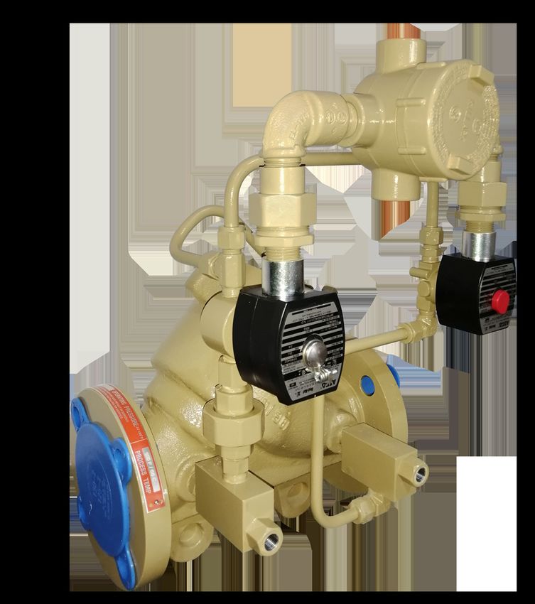
Daniel Series 788 Liquid Control Valve Datasheet
Daniel 788 Digital Control Valve
Overview
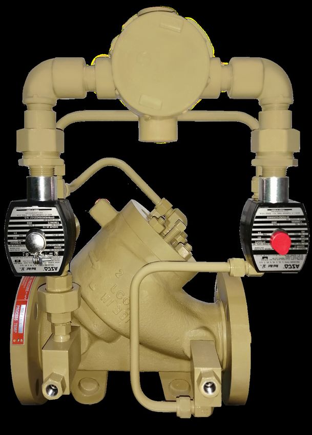
The Daniel 788 Digital Control Valve is designed to provide
precise flow rate control and batch delivery of fluid products
when used with an electronic batch control device (preset).
The Daniel 788 Digital Control Valve is automatically controlled
by the preset for low flow start-up, high flow rate control, low
flow shutdown, and final shut off. This valve also provides for
maximum flowmeter accuracy by maintaining a constant flow
rate with varying line pressures. The Daniel 788 Digital Control
Valve features an external pilot control loop that consists of a
normally open solenoid pilot, a normally closed solenoid pilot,
strainer and opening/closing speed controls.
Applications
The Daniel 788 Digital Control Valve can be used in any
Figure 1: Daniel™ 788 Digital Liquid
application requiring precise flow rate control with batch Control Valve
capability when used with an electronic preset capable of
digital valve control including loading and off-loading
(truck, railcar, ship, barge, etc).
Features and Benefits
Precise flow rate and batch control
Modular construction – All internal parts including
seat and seat ring may be removed as a cartridge
assembly without the need to remove the valve body
from the system piping
No diaphragms or stuffing boxes
45° body design assures high capacity and low
pressure drop
Positive (bubble tight to Class VI) shut-off
Linear control characteristics with uniform response
speed
Fail-safe closure on loss of power
Aggressive Products (AP) Option with Teflon ®
elastomers
www.Emerson.com 1Daniel Series 788 Liquid Control Valve February 2020
Standard Specifications
Please consult Daniel if your requirements are outside the specifications noted below. Other product and material offerings
may be available depending on the application.
Flange Connections / Ratings (ANSI) Valve Capacity
Valve size: 2” to 8”
Table 1: Valve Capacity
Maximum working pressure at 38 °C
ANSI 150: 285 psi (1,964 kPa) Valve
2" 3" 4" 6" 8"
ANSI 300: 740 psi (5,099 kPa) Size
Temperature Range: -20°F to 150 °F (-29°C to 66°C) Cv (GPM) 86 186 309 688 1,296
Optional 250°F (121°C)
Flange Connections / Ratings (DIN) Documentation and Approvals
Valve size: DN50 - DN200
UL and CSA Listed
Maximum working pressure at 38 °C Class I - Groups C and D
DIN PN16 MWP: 16 bar
Class II - Groups E, F and G
DIN PN25 MWP: 25 bar
DIN PN40 MWP: 40 bar Explosion Proof NEMA Types 7C, 7D, 9E, 9F, 9G
DIN PN64 MWP: 51 bar and waterproof NEMA Type 4
CE (ATEX, PED [or SEP] and EMR)
Materials of Construction ATEX II 2G/D EEx d IIC T6-T4
Main Valve Body: Steel - ASTM-A352-GR-LCC
Main Valve Cylinder: 2" - 4" Stainless Steel Heat Treaded 17-4 pH Maximum Operating Pressure
6" - 8" Carbon Steel, Nickel Coated
Main Valve Piston: Stainless Steel
Differential (MOPD) Across Pilots
Seat Ring: Stainless Steel 150 ANSI Standard
8" Carbon Steel, Nickel Coated
150 psid (1,035 kPa)
O-Rings: Viton (Standard)
®
Available in Neoprene, EPR, Kalrez , ® 285 psid (1,967 kPa) (optional)
Teflon ("AP" Valves) (Optional)
®
300 ANSI Standard
Other Internal Parts: Stainless Steel
Pilot Valve / Strainer / 740 psid (5,106 kPa)
Needle Valve Trim: Stainless Steel
Pilot O-Rings: Viton (Standard)
®
Available in Neoprene, EPR, Kalrez , ®
Teflon ("AP" Valves) (Optional)
®
Tubing and Fittings: Stainless Steel
2 www.Emerson.comDaniel Series 788 Liquid Control Valve Datasheet
Standard Equipment
Pre-wired solenoids (optional for CE execution)
Opening and closing speed controls
Self-cleaning strainer (pilot inlet)
Stainless steel solenoid pilots
Stainless Steel tubings and fittings
Optional Equipment
Pre-wiring for valves with CE solenoids
Manual override
Valve position indicator
Thermal relief
Aggressive Products Option
The use of aggressive additives or oxygenates call for the
Aggressive Products, or AP option. The AP option valve cylinder
incorporates cup-seals (Teflon Bal Seals) and an O-ring made
®
from appropriate materials for such challenging conditions.
Materials for pilots such as low swell nitrile (main valve static
O-rings) and Kalrez or Teflon are available.
® ®
Approximate Shipping Weight and Volume
Table 2: Approximate Shipping Weight and Volume
150 ANSI 300 ANSI
Valve Size Shipping Weights Shipping Volume Shipping Weights Shipping Volume
Cubic Cubic Cubic Cubic
lbs Kgs lbs Kgs
Feet Meters Feet Meters
2" 60 27 1.7 .047 65 29 1.8 .050
3" 105 48 2.4 .067 115 52 2.5 .070
4" 140 64 2.5 .071 165 75 3.1 .087
6" 250 114 4.9 .137 290 132 6.0 .169
8" 400 181 8.9 .253 465 212 10.0 .283
www.Emerson.com 3Daniel Series 788 Liquid Control Valve February 2020
Table 4: Dimensions
ANSI 150 ANSI 300
Valve Size B1 No B2 With B1 No B2 With
A C A C
Indicator Indicator Indicator Indicator
10.25" 10.25" 11" 8.25" 10.5" 9" 11" 8.25"
2"
260 mm 229 mm 279 mm 210 mm 267 mm 229 mm 279 mm 210 mm
11" 9" 12" 8.75" 13.125" 9" 12" 8.75"
3"
279 mm 229 mm 305 mm 222 mm 333 mm 229 mm 305 mm 222 mm
13" 9" 12.5" 9" 14.5" 9" 12.5" 9"
4"
330 mm 229 mm 318 mm 229 mm 368 mm 229 mm 318 mm 229 mm
17" 12" 15.75" 11" 17.875" 12" 15.75" 11"
6"
432 mm 305 mm 400 mm 279 mm 454 mm 305 mm 400 mm 279 mm
22.25" 15" 17.5" 11.75" 23.25" 15" 17.5" 11.75"
8"
565 mm 381 mm 445 mm 298 mm 591 mm 381 mm 445 mm 298 mm
4 www.Emerson.comDaniel Series 788 Liquid Control Valve Datasheet
Operational Sequence* Figure 1 Closed or Closing Position
3
-XQFWLRQ%R[
With both solenoids de-energized, the main valve is closed.
The main valve can be infinitely positioned anywhere between
0-100% open by digital control of the solenoids. With both 6ROHQRLG3LORW 1&
solenoids energized, as shown in Figure 2, the valve begins (Y)
to open. It will only open to the programmed flow rate 6ROHQRLG3LORW 12
0DLQ9DOYH6SULQJ
SLVWRQFORVHG
set in the preset. Normally, the preset is programmed to
digitally control low flow startup rate, maximum flow rate,
low flow rate before shut-off and final shut-off. The preset 9DOYH
RSHQ
Flow
will automatically energize and de-energize the solenoids to 9DOYH
FORVHG
position the main valve to attain the required flow rate. When (X)
the required rates are reached the solenoids will be as shown ,QOHW3UHVVXUH
(Z)
in Figure 3. This hydraulically locks the main valve piston in 2XWOHW3UHVVXUH 3
position. Should flow increase, the valve will close slightly to
adjust to the required rate. All of the positioning is done by
digitally controlling the two solenoids as shown in Figures 1, 2 3
and 3. The valve opening and closing speeds can be adjusted Closed or Closing Position - The normally closed solenoid
independently via the two needle valves which are shown is closed. The normally open solenoid is open. Y-Port (P3) to
below. Z-port (P2) is closed. X-port (P1) and Y-port (P3) pressures are
balanced. The main valve spring, being the differential force,
closes the piston and keeps it seated.
Figure 2 Full Open / No Control Figure 3 Controlling Position
3
3
-XQFWLRQ%R[
-XQFWLRQ%R[
6ROHQRLG3LORW 1&
6ROHQRLG3LORW 1&
(Y) (Y)
0DLQ9DOYH6SULQJ
0DLQ9DOYH6SULQJ
6ROHQRLG3LORW 12 SLVWRQRSHQ 6ROHQRLG3LORW 12 SLVWRQORFNHG
9DOYH
9DOYH
FORVHG
Flow FORVHG
9DOYH Flow
9DOYH
RSHQ
FORVHG
(X) (X)
(Z) (Z)
,QOHW3UHVVXUH
,QOHW3UHVVXUH
2XWOHW3UHVVXUH 3
2XWOHW3UHVVXUH 3
3
3
Opening Position - The normally closed solenoid is Controlling Position - The normally closed solenoid is closed.
open. The normally open solenoid is closed. Y-Port (P3) The normally open solenoid is closed. Y-Port (P3) to Z-port (P2)
is open to Z-port (P2). X-port (P1) is closed off by the is closed. X-port (P1) to Y-port (P3) is closed. Note: The product
normally open solenoid. The pressure on the bottom of cannot flow to or from the top of the piston (Y-port). The piston
the piston (P1) is greater than the pressure at (P3) plus is hydraulically locked in position until the preset commands
the spring force; (P1 minus P2) is equal to or greater the valve to open or close as required to maintain the desired
than the spring force. Therefore, (P1) pressure pushes flow rate.
the piston open.
*Please refer to the Daniel 788 Digital Control Valve Operating and Maintenance Manual for all operating instructions and safety information.
www.Emerson.com 5Daniel Series 788 Liquid Control Valve February 2020
Typical Applications
The most common application of the Daniel Model 788 Digital
Control Valve is for truck loading. The figure below shows the
Daniel 788 Digital Control Valve working with turbine meters
and electronic preset to precisely control flow rates, batch
quantities and blend ratio's of various products being loaded.
Load Rack Installation with Daniel 788 Digital Control Valve for Ratio Blending
3XPS&RQWDFWV
5HPRWH
0HWHU3XOVHV 7RWDOL]HU
)DFWRUHG3XOVH
7HPSHUDWXUH 12,569 Liters SHU6WUHDP
56
$XWRPDWLRQ
'LJLWDO9DOYH &RPSXWHU
1 2 3
4 5 6
56 %DFNXS
7 8 9 0
%2/3ULQWHU
DL8000
8
$GGLWLYH
,QMHFWLRQ
$GGLWLYH $GGLWLYH $GGLWLYH 7HPS 'HQVLW\ 6
3XPS 0HWHU 6ROHQRLG
6 www.Emerson.comDaniel Series 788 Liquid Control Valve Datasheet
Daniel 788 Digital Control Valve
Product Datasheet X XX X X X X X X X X X X X X X
Device NACE
Control Valve V A None
Line Size B NACE
2" DN50 02 Approvals
3" DN80 03 E UL/CSA Certified Electric Component
4" DN100 04 6 CE (ATEX/PED/SEP)
6" DN150 06 Manual Override and Position Indicator
8" DN200 08 A None
Flange Rating/Maximum Working Pressure B Manual Override
ANSI 150 D Manual Override and Visual Indicator (3)
285 PSI MWP / 150 PSI MOPD 1,034 kPa MWP A E Manual Override and Indicator w/Guard & 1 Switch
ANSI 150 F Manual Override and Indicator w/Guard & 2 Switches
285 PSI MWP / 250 PSI MOPD 1,965 kPa MOPD B G Manual Override and Visual Indicator
ANSI 300 740 PSI MWP 5,102 kPa MWP C H Manual Override and Indicator w/Guard & 1 Switch
PN16 DIN 2526 Form C 16 BAR MWP/ 10.3 BAR MOPD H J Manual Override and Indicator w/Guard & 2 Switches
PN16 DIN 2526 Form C 16 BAR MWP/ 20 BAR MOPD J Q Visual Indicator
PN16 DIN 2526 Form C 25 BAR MWP K R Indicator w/Guard & 1 Switch
PN16 DIN 2526 Form C 40 BAR MWP L S Indicator w/Guard & 2 Switches
ANSI 150 Replacement for 1815 T Indicator w/Guard & No Switch
150 PSI MOPD LIMIT (Includes AP Option) R 1 Manual Override and Indicator w/Guard & No Switch
ANSI 300 Replacement for 1830 Accessories
150 PSI MOPD LIMIT S A None
MATERIALS OF CONSTRUCTION C Thermal Relief
Valve D XYZ Block
Carbon Steel B Q Thermal Relief and XYZ Block
Low Temp Carbon Steel C Pilots Voltage
Nickel Coated Carbon Steel D 3 24 Vdc
Piston 6 110/120 Vac
Stainless Steel B 7 220/240 Vac4
9 110/120 Vac (Class H High Temperature Coil) up to 356°F (180°C)
Pilot Body
0 220/240 Vac (Class H High Temperature Coil) up to 356°F (180°C)
Carbon Steel B
Stainless Steel C Pilot Elastomers
Tubbing and Fittings B All Viton Parker V747 75 (-15F to 400F) (-26C to 204C)
®
Stainless Steel SAE B C Viton GFLT - Parker V1163-75 (-35F to 400F)(-37C to 204C)
®
D Viton Parker V1289-75 -Low Temp (-50F to 400F) (-46C to 204C)
®
Stainless Steel Metric C
E Viton for LPG Service
®
Main Valve Construction
F EPR
Standard B
G Neoprene
Aggressive Product C
H Nitrile
Main Valve Elastomes L Kalrez Dynamic / Low Swell Nitrile Static
®
All Viton Parker V747-75 (-15F to 400F) (-26C to 204C) B
®
M Teflon 1714/1715 Pilots Only(11)
®
Viton GFLT - Parker V1163-75 (-35F to 400F)(-37C to 204C) C
®
N Simriz O-rings (150 psi MOPD) 1714/1715 Pilots Only
Viton Parker V1289-75 -Low Temp (-50F to 400F) (-46C to 204C) D
®
O All Kalrez ®
Viton for LPG Service E
®
P Viton (150 psi MOPD) 1714/1715 Pilots Only
All EPR F
All Neoprene G
All Nitrile H
Teflon Dynamic/ Low Swell Nitrile Static K
Kalrez O-rings L
®
www.Emerson.com 7Emerson Automation Solutions
Daniel Measurement and Control, Inc. Middle East, Africa: Dubai, UAE
North America / Latin America: T +971.4.811.8100
Headquarters Asia Pacific: Singapore
USA - Houston, Texas T +65.6777.8211
T +1.713.467.6000
USA Toll Free 1.888.FLOW.001
www.Emerson.com/Daniel
©2019 Daniel Measurement and Control, Inc. All Rights Reserved. Unauthorized duplication in
whole or in part is prohibited. Printed in the USA. DAN-LIQ-DS-788-0220
The Emerson logo is a trademark and service mark of Emerson Electric Co. Daniel Measurement
and Control, Inc. ("Daniel") is an Emerson Automation Solutions business unit and a subsidiary
of Daniel Industries, Inc. The Daniel name and logo are trademarks of Daniel Industries, Inc. All
other trademarks are the property of their respective companies.You can also read