DEHUMIDIFIERS PCP SERIES - OPERATION AND MAINTENANCE MANUAL - Dehumidified Air Services
←
→
Page content transcription
If your browser does not render page correctly, please read the page content below

PCP SERIES
DEHUMIDIFIERS
  Indoor

OPERATION AND MAINTENANCE MANUAL

PoolPak.com
PoolPak PCP Series – Indoor OMM 2 September 2021
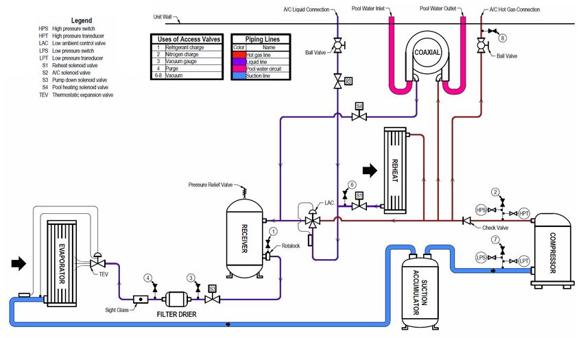
Table of Content
General Information 4
Operating Safety 4
Reference and Additional Information 5
o Contact Us 5
Basic Information 6
o Dehumidifier View and Options – S Cab 6
o Dehumidifier View and Options – RV and RH Cabs 8
o Dehumidifier View and Options – SLB Cab 12
o Air Conditioning Option – Outdoor Air Condensers 15
o Air Conditioning Option – Fluid Coolers 16
o Equipment Specific Data 18
Layout and Components 19
Dehumidifier Main Components – S and SLB Cab 19
Dehumidifier Main Components – RV and RH Cabs 21
Control System 24
Outdoor Air Condensers and Fluid Coolers Layout and Components 27
Sequence of Operation 29
Set Points 30
Ventilation 30
Space Heating 30
Air Conditioning, Dehumidification and Pool Heating 30
o Compressor(s) 30
Interface and Communication 31
Touch Display Operator Panel 31
o Alarms 32
Remote Communication 33
Basic Maintenance 34
Maintenance and Safety 34
Maintenance Key Points 34
Routine Maintenance Program 35
Specific Components Maintenance 36
Warranty 38
September 2021 3 PoolPak PCP Series – Indoor OMM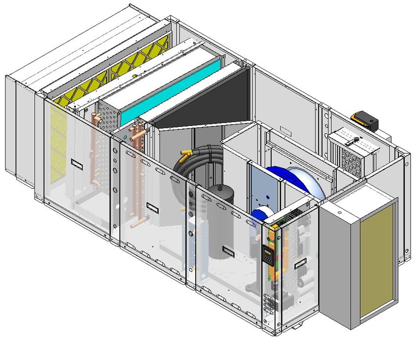
General Information
This manual provides basic information about the applicable dehumidifier and its operation.

Important information regarding installation, maintenance, and start up as well as additional and auxiliary systems
and devices (outdoor condenser, communication interfaces, etc.) is normally provided with the dehumidifier and
can also be obtained at factory (see Contact Us below).

Operating Safety (Warnings, Cautions, and Notes)

FOR YOUR SAFETY: READ BEFORE PERFORMING ANY OPERATIONS, MAINTENANCE OR SERVICE TASKS!

                 Only qualified technicians should install, operate, maintain or service mechanical equipment
                 including current dehumidification system.
                 Make sure to read this manual before performing any tasks to familiarize yourself with the
                 equipment as well as with any potential hazards. Always exercise caution!

                                     Beware of electrical power and high electrical voltage!
                 •    Follow proper safety procedures – lockout, tagout, and other respective procedures
                 •    Failure to follow safety procedures can result in serious injury or death

                                            Beware of moving parts and hot surfaces!
                 •    Make sure to stop all moving parts (fans, blowers, etc.) before accessing the equipment’s
                      internal space
                 •    Be aware of hot surfaces (hot refrigeration, space heating pipes, coils, heaters, etc.)

                                            Beware of high pressures and chemicals!
                 •    Dehumidifiers, equipped with compressors, contain refrigerant under high pressure; oil is
                      also contained in the compressor and refrigeration circuit(s)
                 •    Some dehumidifiers may also contain other liquids such as glycol mixtures and pool water

The following warnings, cautions, and notes appear throughout this manual and referenced documentation
whenever special care must be taken to avoid potential hazards that could result in equipment malfunction or
damage, personal injury, or death.

      WARNING                                 CAUTION                          Note
Indicates a potentially hazardous       Indicates a potentially hazardous      Indicates a situation that could
situation which could result in         situation which could result in        result in equipment damage or
serious injury or death if handled      moderate injury or equipment           improper/ineffective operation if
improperly.                             damage if handled improperly.          handled improperly.

PoolPak PCP Series – Indoor OMM                          4                                        September 2021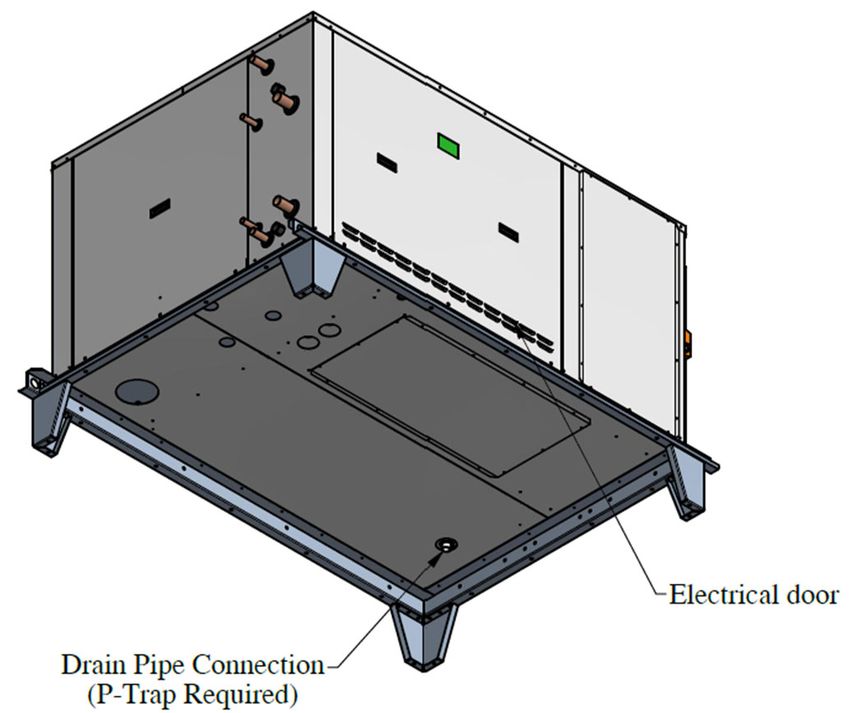
Reference and Additional Information

For safe, efficient and problem‐free operation, it is critical to handle the dehumidifier (as well as related systems
and components) properly at each step ‐ from receiving and storage to installation and start up. Relevant
information can be found in the respective documents (like Installation Manual) provided with the dehumidifier.
This manual and other related documents could be obtained from the manufacturer (see Contact Us below).

                             Attention: Installation and Service Contractors

      WARNING! Any work (installation, start up, service, maintenance, repair, etc.) on any mechanical
equipment (dehumidifier, outdoor condenser, fluid cooler, etc.) must be performed in accordance with
respective manufacturer’s recommendations as well as submittal documentation, local Codes and Regulations,
and appropriate field practices. Failure to do so could result in personal injury, equipment damage or
malfunction, and will void equipment warranty. Only qualified and properly trained individuals should perform
tasks on this equipment.

                                        Attention: Maintenance Team
      CAUTION. To ensure equipment longevity and proper and efficient operation, the dehumidifier and its
auxiliary systems and devices (outdoor condenser, fluid cooler, etc.) should be maintained properly and regularly.
Failure to do so could negatively affect premise comfort levels and people’s health. It could also lead to
equipment damage, malfunction, premature tear and ware and may void equipment warranty.

Contact Us

 PoolPak                              1‐833‐DAS‐POOL (327‐7665)
 3491 Industrial Drive
 York, PA 17403                       Schedule / Modify a Start‐up:
 USA                                           Startups@DehumidifiedAirServices.com
                                      Inquire about Warranty:
 PoolPak.com                                   Warranty@DehumidifiedAirServices.com
                                      Order Parts:
                                               Parts@DehumidifiedAirServices.com
                                      All Other Product Support:
                                               Support@DehumidifiedAirServices.com

September 2021                                            5                       PoolPak PCP Series – Indoor OMM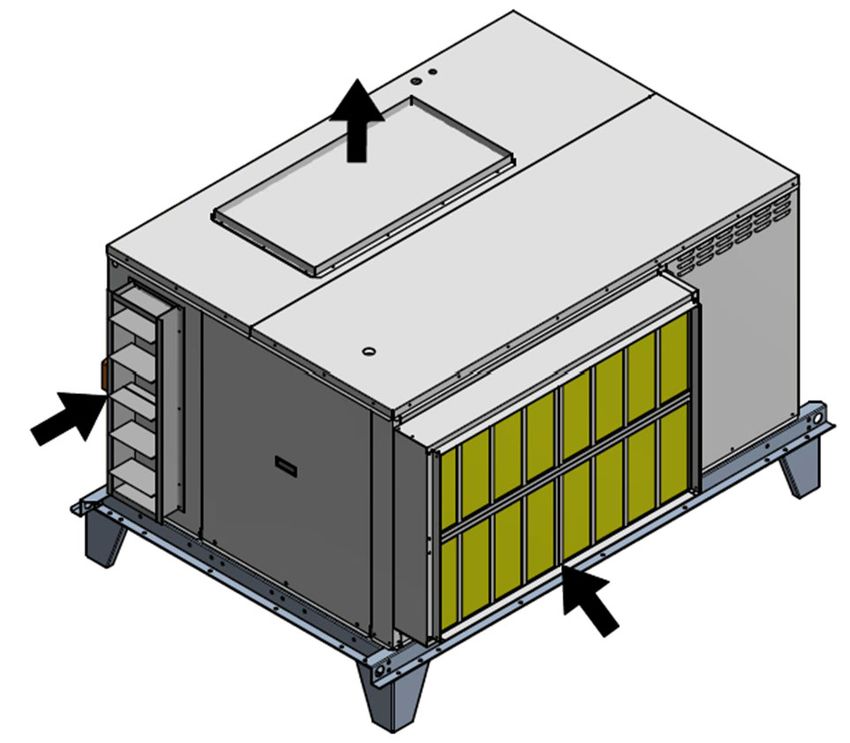
Basic Information
Dehumidifier View and Options – S Cab
Standard PCP800 and PCP1200 dehumidifier’s general views and options * are shown on Pic.C.1.
Options:
Return Air (RA) ductwork connection ‐
horizontal.
Supply Air (SA) ductwork connection
options – top, bottom, horizontal*.
Outdoor Air (OA) intake ‐ horizontal*.
Piping Connections
① Condensate Drain
② AC – Air‐Cooled (refrigeration)
③ AC – Water‐Cooled (water/glycol)
④ Pool Heating Water
⑤ Space Heating Hot Water
Pic. C.1
Dehumidifier Options:
Indoor, single‐compressor dehumidifiers 2 and 3 tons’ capacity (apprx.) ‐ models PCP800 and PCP1200 *.
o Two‐compressor dehumidifier option (see Dehumidifier Optional Arrangement below for details):
4 and 6 ton cooling capacity (appx.) ‐ models PCP808 and PCP1212.
Airflow and ductwork connection options* (Return Air, Supply Air, Outdoor Air) ‐ as shown on Pic. C.1.
Optional Pool Water Heating **.
Optional Space Heating ‐ hot water coil, electric or gas heater ***.
Air Conditioning (AC)* – external water cooling, outdoor condenser or fluid cooler.
PoolPak PCP Series – Indoor OMM 6 September 2021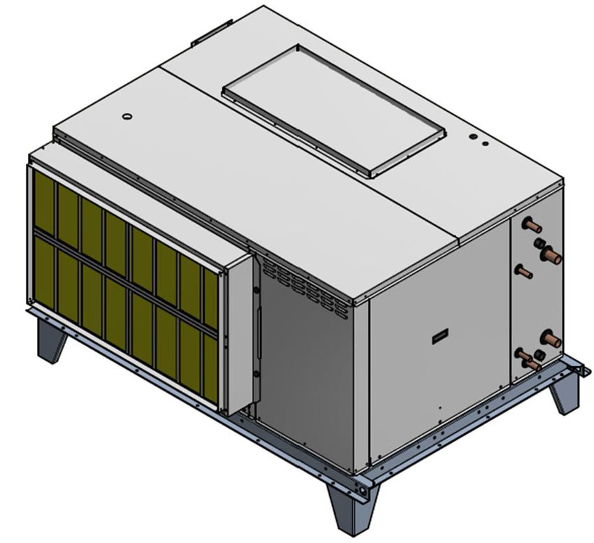
* All available options (tonnage, ductwork connections, AC options etc.) are shown. Refer to the submittal
and other relevant documentation for your equipment options, dimensions etc.
** The pool water heating option relies on compressor‐created excess heat and is used as an additional
heating source. It does not eliminate the need for a main pool water heater.
*** For specific details on space heating (hot water, gas, electric) option, refer to the submittal and other
documentation:
Gas‐fired duct heater can be provided for field installation (to be fitted in the supply air ductwork).
Electric heater or hot water coil, depending on capacity, model, size, etc., can be installed externally (mounted on the
top of SA opening or fitted in the supply air ductwork) or internally. Refer to your dehumidifier’s submittal
documentation.
Attention! Equipment Clearances and Dimensions!
CAUTION! For equipment proper operation, maintenance and service, respective clearances should be
maintained. Generally, 30” clearances to the equipment must be kept for the maintenance and service purposes.
For the specific required clearances information, as well as dehumidifier overall dimensions, distances to pipe
connections, duct connections etc., refer to the submittal documentation.
Dehumidifier External Systems Connection – S Cab
Pic. C.1 shows provisions for external systems connections, including ductwork, electric power and control wires
and various piping connections.
CAUTION! Current manual shows general/default connections’ location. For details regarding specific
dehumidifier’s connections (actual location, piping sizes and position dimensions, circuit type and flow direction
etc.), refer to the dehumidifier’s submittal documentation as well as dehumidifier’s labels and stickers.
Except for the condensate, all other piping systems are optional and may not be present in each dehumidifier.
NOTE. Dehumidifier MUST be equipped with a P‐trap at the condensate connection for proper operation! If
dehumidifier is requested/provided from the factory without P‐trap, one MUST be installed on site prior to
dehumidifier being commissioned. Refer to the dehumidifier stickers and Installation Manual for details.
Air Conditioning (AC) Connection. Normally, the dehumidifier has only one AC option – air‐cooled (requiring
connection to the outdoor air condenser) or water‐cooled (requiring connection to the fluid cooler or other
external water‐cooled system such as geothermal, cooling tower, etc.). Therefore, only one of these options
present with the actual dehumidifier.
Gas line. If the dehumidifier is equipped with a gas heater for space heating purposes, the gas line connection
is to be brought to the gas heater directly.
WARNING! Gas Line. The gas line must be installed in accordance with respective device documentation
and local codes and regulations.
September 2021 7 PoolPak PCP Series – Indoor OMM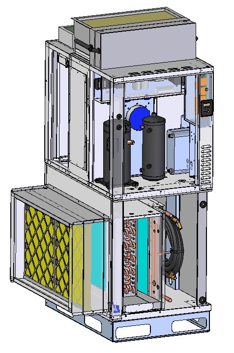
Dehumidifier View and Options – RV and RH Cabs
Standard PCP1400 – PCP2600 dehumidifiers come in vertical (Pic.C.1‐A) or horizontal (Pic.C.1‐B) composition:
Vertical Composition
Return Air (RA) ductwork connection ‐
horizontal.
Supply Air (SA) ductwork connection
options – top, horizontal (left or right).
Outdoor Air (OA) intake ‐ top
Piping Connections
① Condensate Drain
② AC – Air‐Cooled (refrigeration)
③ AC – Water‐Cooled (water/glycol)
④ Pool Heating Water
⑤ Space Heating Hot Water
Pic. C.1‐A
PoolPak PCP Series – Indoor OMM 8 September 2021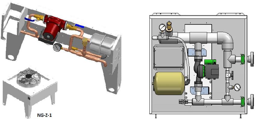
Horizontal Composition
Return Air (RA) ductwork connection ‐
horizontal.
Supply Air (SA) ductwork connection
options – top, bottom, horizontal (straight).
Outdoor Air (OA) intake ductwork
connection options – top, horizontal.
Piping Connections
① Condensate Drain
② AC – Air‐Cooled (refrigeration)
③ AC – Water‐Cooled (water/glycol)
④ Pool Heating Water
⑤ Space Heating Hot Water
Pic. C.1‐B
September 2021 9 PoolPak PCP Series – Indoor OMM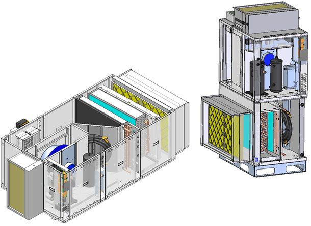
Dehumidifier Options (applicable to both, vertical and horizontal, configurations):
Indoor, single‐compressor dehumidifiers, 4 to 7 ton cooling capacity (apprx.) ‐ models PCP1400 to PCP2600 *.
o Two‐compressor dehumidifier option (see Dehumidifier Optional Arrangement below for details):
8 to 14 ton cooling capacity (appx.) ‐ models PCP1414 to PCP2626
Airflow and ductwork connection options* (Return, Supply and Outdoor Air) ‐ see Pic. C.1‐A and C.1 – B.
Optional Pool Water Heating **.
Optional Space Heating ‐ hot water coil, electric or gas heater ***.
Air Conditioning (AC)* – external water cooling, outdoor condenser or fluid cooler.
* All available options (tonnage, ductwork connections, AC options etc.) are shown. Refer to the submittal
and other relevant documentation for your equipment options, dimensions etc.
** The pool water heating option relies on compressor‐created excess heat and is used as an additional
heating source. It does not eliminate the need for a main pool water heater.
*** For specific details on space heating (hot water, gas, electric) option, refer to the submittal and other
documentation:
Gas‐fired duct heater can be provided for field installation (to be fitted in the supply air ductwork).
Electric heater, depending on various factors (capacity, model, size, etc.), can be installed externally (mounted on the
top of SA opening) or internally. Refer to your dehumidifier’s submittal documentation.
Attention! Equipment Clearances and Dimensions!
CAUTION! For equipment proper operation, maintenance and service, respective clearances should be
maintained. Generally, 30” clearances to the equipment must be kept for the maintenance and service purposes.
For the specific required clearances information, as well as dehumidifier overall dimensions, distances to pipe
connections, duct connections etc., refer to the submittal documentation.
Dehumidifier External Systems Connection – RH and RV cabs
Pic. C.1 – A and B show provisions for external systems connections, including ductwork, electric power and
control wires and various piping connections.
CAUTION! Current manual shows general/default connections’ location. For details regarding specific
dehumidifier’s connections (actual location, piping sizes and position dimensions, circuit type and flow direction
etc.), refer to the dehumidifier’s submittal documentation as well as dehumidifier’s labels and stickers.
Except for the condensate, all other piping systems are optional and may not be present in each dehumidifier.
NOTE. Dehumidifier MUST be equipped with a P‐trap at the condensate connection for proper operation! If
dehumidifier is requested/provided from the factory without P‐trap, one MUST be installed on site prior to
dehumidifier being commissioned. Refer to the dehumidifier stickers and Installation Manual for details.
Air Conditioning (AC) Connection. Normally, the dehumidifier has only one AC option – air‐cooled (requiring
connection to the outdoor air condenser) or water‐cooled (requiring connection to the fluid cooler or other
external water‐cooled system such as geothermal, cooling tower, etc.). Therefore, only one of these options
present with the actual dehumidifier.
Gas line. If the dehumidifier is equipped with a gas heater for space heating purposes, the gas line connection
is to be brought to the gas heater directly.
WARNING! Gas Line. The gas line must be installed in accordance with respective device documentation
and local codes and regulations.
PoolPak PCP Series – Indoor OMM 10 September 2021Dehumidifier Optional Arrangement – RH and RV Cabs
Mirrored Arrangement
Both, horizontal and vertical, dehumidifier could have standard and mirrored cabinet arrangement (see Pic.C.2).
Note, that all options and details, described above, apply to both, standard and mirrored arrangement.
Pic. C.2
September 2021 11 PoolPak PCP Series – Indoor OMMDehumidifier View and Options – SLB cab
Standard PCP3000 – PCP5000 dehumidifiers views and options are shown in Pic.C.1 below.
Return Air (RA) ductwork connection ‐
horizontal. SA
Supply Air (SA) ductwork connection
options – top, bottom, horizontal side
(supply end).
Outdoor Air (OA) intake ductwork
connection option – left side.
Piping Connections
① Condensate Drain
OA
② AC – Air‐Cooled (refrigeration)
③ AC – Water‐Cooled (water/glycol)
④ Pool Heating Water
⑤ Space Heating Hot Water
OA Damper
(Removable) RA
Electrical connection Blower
Door Legs
(Removable)
6
5
4
3
2 4
5
Filter
Access Compressor
Door
1
Pic. C.1‐A
PoolPak PCP Series – Indoor OMM 12 September 2021Dehumidifier Options (applicable to both, vertical and horizontal, configurations):
Indoor, single‐compressor dehumidifiers, 8 to 16 tons’ capacity (apprx.) ‐ models PCP3000 to PCP5000 *.
o Two‐compressor dehumidifier option (16 to 32 tons’ capacity (appx.) ‐ models PCP3030 to PCP5050 ‐
see Dehumidifier Optional Arrangement below.
Airflow and ductwork connection options (Return Air (RA), Supply Air (SA) Outdoor Air (OA)) * ‐ as shown on
Pic. C.1‐A.
Optional Pool Water Heating **.
Optional Space Heating ‐ hot water coil, electric or gas heater ***.
Air Conditioning (AC)* – external water cooling, outdoor condenser or fluid cooler.
* All available options (tonnage, ductwork connections, AC options etc.) are shown. Refer to the submittal
and other relevant documentation for your dehumidifier’s options.
** The pool water heating option relies on compressor‐created excess heat and is used as an additional
heating source. It does not eliminate the need for a main pool water heater.
*** For specific details on space heating (hot water, gas, electric) option, refer to the submittal and other
documentation:
Gas‐fired duct heater can be provided for field installation (to be fitted in the supply air ductwork).
Electric heater or hot water coil, depending on capacity, model, size, etc., can be installed externally (mounted on the
top of SA opening or fitted in the supply air ductwork) or internally. Refer to your dehumidifier’s submittal
documentation.
Attention! Equipment Clearances and Dimensions!
CAUTION! For equipment proper operation, maintenance and service, respective clearances should be
maintained. Generally, 30” clearances to the equipment must be kept for the maintenance and service purposes.
For the specific required clearances information, as well as dehumidifier overall dimensions, distances to pipe
connections, duct connections etc., refer to the submittal documentation.
Dehumidifier External Systems Connection
Pic. C.1 – A shows provisions for external systems connections, including ductwork, electric power and control
wires and various piping connections.
CAUTION! Current manual shows general/default connections’ location. For details regarding specific
dehumidifier’s connections (actual location, piping sizes and position dimensions, circuit type and flow direction
etc.), refer to the dehumidifier’s submittal documentation as well as dehumidifier’s labels and stickers.
Except for the condensate, all other piping systems are optional and may not be present in each dehumidifier.
NOTE. Dehumidifier MUST be equipped with a P‐trap at the condensate connection for proper operation! If
dehumidifier is requested/provided from the factory without P‐trap, one MUST be installed on site prior to
dehumidifier being commissioned. Refer to the dehumidifier stickers and Installation Manual for details.
Air Conditioning (AC) Connection. Normally, the dehumidifier has only one AC option – air‐cooled (requiring
connection to the outdoor air condenser) or water‐cooled (requiring connection to the fluid cooler or other
external water‐cooled system such as geothermal, cooling tower, etc.). Therefore, only one of these options
present with the actual dehumidifier.
September 2021 13 PoolPak PCP Series – Indoor OMM Gas line. If the dehumidifier is equipped with a gas heater for space heating purposes, the gas line connection
is to be brought to the gas heater directly.
WARNING! Gas Line. The gas line must be installed in accordance with respective device documentation
and local codes and regulations.
Dehumidifier Optional Arrangement.
Two‐Compressor Arrangement
Standard PCP series dehumidifier has one compressor,
however two‐compressor arrangement is available also. Note,
that all options and details, provided above, apply to both,
standard and two‐compressor arrangement:
Single Deck dehumidifier has same dimensions,
features and options as standard single‐compressor
one, except for two compressor/refrigeration circuits
instead of one.
“Double‐Decker” dehumidifier is shown on Pic. C.3.
It is composed of two identical dehumidifiers, one
installed on top of another and controlled as a single
Pic. C.3
dehumidifier (each deck is equipped with one
compressor/refrigeration circuit).
Single and Two‐Compressor Arrangement – Dehumidifier Model
Dehumidifier typical arrangement, total capacity, and number of compressors are reflected in its model (for
specific dehumidifier model refer to its Main Label – see Specific Data Info below):
PCP3000 to PCP5000 models – single‐deck single‐compressor dehumidifier.
Two ‐compressor PCP series dehumidifier:
PCP3030 to PCP5050 models ‐ double‐deck two‐compressor dehumidifier, composed of two identical single‐
deck single‐compressor dehumidifiers (thus doubling the capacity).
Most often, “Double‐Decker” comes as two horizontal dehumidifiers, one “stacked” on the top of another,
however it could also be composed of two dehumidifiers (horizontal OR vertical) installed side by side or
separately, still being controlled as one.
PoolPak PCP Series – Indoor OMM 14 September 2021Air Conditioning Option ‐ Outdoor Air Condensers (OACC)
Basic views of standard outdoor air condensers are shown on
Table C.1.C Dehumidifier‐AC Combination*
Pic.C.4‐C (below); standard combinations of the dehumidifier Dehumidifier – Outdoor Condenser** Fig.#
and outdoor air condensers are shown in Table C.1.C PCP0800 – PCP1200 NC‐B 1
PCP0808 – PCP1212
* Table C.1.C shows standard dehumidifier and PCP1400 – PCP3000 NC‐Z‐1 2
condenser combination; depending on number of factors, PCP3500 – PCP 5000 NC‐Z‐2 3
dehumidifier may have different condenser provided with it ‐ PCP1414 – PCP3030
refer to the dehumidifier’s submittal documentation for more PCP3535‐PCP5050 NC‐Z‐4 ‐
details.
Attention! Equipment Clearances!
Proper clearances should be maintained for adequate airflow and heat rejection! Generally, up to 36” side and
96” top clearances are required. For more information on clearances as well as equipment dimensions and other
details, refer to the submittal documentation.
** Two‐compressor dehumidifier would normally have paired‐up two outdoor condensers of respective size
(one per compressor). For example, PCP0808 would have double‐condenser, composed of two NC‐B (see Pic.C.4.C,
Fig.1).
Pic. C.4.C
September 2021 15 PoolPak PCP Series – Indoor OMMAir Conditioning Options ‐ Fluid Coolers (OAFC).
Basic views of standard fluid coolers are shown on Pic.C.4.F (below); standard combinations of the dehumidifier
and respective fluid coolers (based on their capacities) are shown in Table FC.1.
* Table FC.1 shows standard dehumidifier and cooler Table FC.1. Dehumidifier‐FC Combination*
combination; depending on number of factors, dehumidifier Dehumidifier – Fluid Cooler** Fig.#
may have different cooler provided with it ‐ refer to the PCP0800 – PCP1200 NG‐Z‐1 4
dehumidifier’s submittal documentation for more details. PCP1400 – PCP2600 NG‐V‐0 5
PCP0808 – PCP1212
** The pump package is optional ‐ the fluid cooler may PCP3000 – PCP4000, NG‐V‐11 6
be provided without it. PCP1414 – PCP1818
PCP4500 – PCP5000, NG‐V‐12 7
PCP2626 – PCP4040
PCP4545 – PCP5050 NG‐V‐22 8
Attention! Equipment Clearances!
Proper clearances should be maintained for adequate airflow and heat rejection! Generally, up to 36” side and
96” top clearances are required. For more information on clearances as well as equipment dimensions and other
details, refer to the submittal documentation.
PoolPak PCP Series – Indoor OMM 16 September 2021Fig. 4.
Fig. 5.
Fig. 6. Fig. 7.
Pic. C.4.F
Fig. 8.
September 2021 17 PoolPak PCP Series – Indoor OMMEquipment Specific Data
Specific information for individual dehumidifiers is provided in the following methods:
Main Label (Pic. C.5): the manufacturer tag
attached to the front of the dehumidifier
includes the dehumidifier’s most critical data:
General data including:
o Serial number
o Dehumidifier model
(nomenclature)
o Design room conditions (air
temperature and humidity)
Operational data, including:
o Refrigeration (refrigerant type,
charge, etc.)
o Electrical/airflow (dehumidifier
voltage, CFM, etc.)
o Other applicable data (pool heating,
space/auxiliary heating features,
etc.)
Labels and Stickers: attached when applicable to
the exterior and interior of the dehumidifier to
show:
External systems connections
location/direction
(pool/space heating, cooling circuits,
condensate) Pic. C.5
Air filter locations, quantity, and size.
Additional Info (warning, caution stickers, etc.)
Wiring Diagrams: attached to the interior side of Note: The main label shown above is just an example.
the dehumidifier, depict dehumidifier control and
power wiring.
Remotely installed condenser or cooler would have its specific information provided in similar manner (labels etc.).
Attention! Glycol Circuits.
Unless otherwise indicated, equipment fluid circuits (except for refrigeration and pool water circuits) such as heat
recovery loop, compressor glycol loop, fluid cooler etc., are normally filled/to be filled with water/glycol mixture;
normally, rust inhibitor‐infused food‐grade propylene glycol is used.
Glycol mixture concentration is normally shown on Main Label – refer as needed.
PoolPak PCP Series – Indoor OMM 18 September 2021Layout and Components
The general layout and components location is the same for all dehumidifiers of current type, however some may
vary, based on the dehumidifier’s specific options – refer to submittal documentation. Pic. D.1‐S, D.1A‐RV,
D.1B‐RH below show all/most available options, some of which may not be present on
your dehumidifier. SLB cab is not shown but is more similar to the S cab.
Dehumidifier Main Components – S cab
7 8 10
9
11 4
5
15
13
18
2 1
3
17
16
14
Pic. D.1‐S
Main Blower (1) is in the main blower compartment next to the Main Electric Panel (2) and Compressor
Compartment (3).
September 2021 19 PoolPak PCP Series – Indoor OMM Min Outdoor Air (OA) Opening (4) is optionally equipped with a motorized damper and filter(s). The Manual
OA Damper (5) is usually used to set proper amount of outdoor air intake.
Refrigeration coils ‐ Evaporator (7) and Reheat (internal condenser) (8) ‐ are located directly downstream of
the Main Filter Rack (9).
o Evaporator Bypass Damper (10) is located next to the evaporator coil. It helps to control compressor
suction pressure by adjusting the amount of air, bypassing the evaporator.
Space heater (11) location, if the dehumidifier is equipped with one, may vary:
o Hot water coil is usually located directly downstream of the reheat coil;
o Electric heater may be in the same place as the hot water coil or mounted directly on the
dehumidifier’s supply air duct connection.
o Gas heater normally is installed externally.
Compressor (13), Receiver (14) and other components are located within the Compressor Compartment (3).
o If the dehumidifier has the standard pool water heating option, the compressor circuit includes the
coaxial pool water heat exchanger (15) and refrigeration pool valve.
o If the dehumidifier has the water‐cooled air conditioning option (equipped with fluid cooler or
connected to external water‐cooling source), the compressor circuit also includes the plate heat
exchanger (16)).
Main Electric Panel contains Main Control Board (17), Operator Panel (18) and other electrical components.
PoolPak PCP Series – Indoor OMM 20 September 2021Dehumidifier Main Components – RV and RH Cabs
11
4
17
5 2
18
13
1
8
16
7
14
9
3
11
15
10
RV Cab
Pic. D.1A‐RV
September 2021 21 PoolPak PCP Series – Indoor OMMRH Cab 9 7 8
11
5 4
10 15
14 16 3
1
17
13 18 2
Pic. D.1B‐RH
Main Blower (1) is in the main blower compartment next to the Main Electric Panel (2) and Compressor
Compartment (3).
Min Outdoor Air (OA) Opening (4) is optionally equipped with a motorized damper and filter(s). The Manual
OA Damper (5) is usually used to set proper amount of outdoor air intake.
Refrigeration coils ‐ Evaporator (7) and Reheat (internal condenser) (8) ‐ are located directly downstream of
the Main Filter Rack (9).
o Evaporator Bypass Damper (10) is located next to the evaporator coil. It helps to control compressor
suction pressure by adjusting the amount of air, bypassing the evaporator.
Space heater (11) location, if the dehumidifier is equipped with one, may vary:
o Hot water coil is usually located directly downstream of the reheat coil;
o Electric heater is usually mounted directly on the dehumidifier’s supply air duct connection.
o Gas heater (duct heater or boiler package) normally is installed externally (not shown).
PoolPak PCP Series – Indoor OMM 22 September 2021 Compressor (13), Receiver (14) and other components are located within the Compressor Compartment (3).
o If the dehumidifier has the standard pool water heating option, the compressor circuit additionally
includes the coaxial pool water heat exchanger (15) and refrigeration pool water heating valve.
o If the dehumidifier has the water‐cooled air conditioning option (equipped with fluid cooler or
connected to external water‐cooling source), the compressor circuit also includes the plate heat
exchanger (16).
Main Electric Panel contains Main Control Board (17) and other electrical components.
o Vertical dehumidifier normally has Main Control Board mounted in the additional control sub‐panel,
within Compressor Compartment and separately from Main Electric Panel.
o Operator Panel (TouchDisplay) could be installed inside the dehumidifier (normally – in the
compressor compartment) or provided separately for field installation. Feasible field installation
options include OP mounting plate (18) on the corner post or elsewhere in mechanical room or
maintenance office (see Interface and Communication for details).
September 2021 23 PoolPak PCP Series – Indoor OMMControl System
The dehumidifier control system is composed of sensors, spread throughout the dehumidifier, Main Control
Board, Operator Panel and other electric components, located in the Main Electric Panel.
Temperature Sensors (Pic. D.2):
a) Temperature sensors (thermistors) are used to monitor
various temperatures (air, water, compressor, etc.); a b
b) Combo sensor is used to monitor air temperature and
humidity.
d
Pic. D.2
Compressor operation is monitored with pressure sensors (Pic. D.3):
c c) Pressure Transducers (as main operational control and safety) and
d) Pressure Switches (fast‐reacting backup safety).
Pic.D.3
Sensors and safeties approximate location is shown on Pic. D.4‐S and D.4‐R (see below).
RA Combo Sensor (21) measures temperature and humidity of the pool room air (Return Air) entering the
dehumidifier. It is located at the return air ductwork connection to thedehumidifier.
OA Temperature Sensor (22) measures outdoor air temperature; it’s located at the OA filter rack.
o As an option, the combo sensor (instead of regular thermistor) can be installed at the OA intake to
measure both the temperature and humidity of the outdoor air.
ET (EvapT) Temperature Sensor (23) measures the temperature of air leaving evaporator coil. It’s located
directly downstream of the evaporator.
SA temperature sensor (24) measures the temperature of the air leaving the dehumidifier (supplied to the
premise). It must be located downstream of the space heater:
o In some cases, where the space heater is external to dehumidifier, the sensor will be provided with
the dehumidifier to be field‐mounted into the supply air ductwork downstream of the space heater.
If the dehumidifier is equipped with the pool heating option, the Pool Water Temperature sensors (Pool In
(25) and Pool Out (26)) measure the entering and leaving pool water temperature. The sensors are located
directly at the respective connections of the coaxial pool water heat exchanger.
o As an option, the pool water heat exchanger piping/manifold may have water flow switch also.
The compressor’s discharge line (high pressure side) is equipped with Temperature and Pressure sensors set ‐
Discharge Temperature Sensor, High Pressure Transducer and High Pressure Switch (27) ‐ to protect the
compressor and control its operation. A similar function is performed by Suction Temperature Sensor, Low
Pressure Transducer and Low Pressure Switch (28) located at compressor’s suction line (low pressure side).
Main Electric Panel, apart from devices listed above (control board, OP, etc.) also contains Voltage Monitor;
some optional control sensors and devices such as an air pressure differential sensor, current sensor(s). It may
also be located in main electrical panel or in the dehumidifier in general.
PoolPak PCP Series – Indoor OMM 24 September 202123 22
21
24
26
27
25
28
Pic. D.4‐S
September 2021 25 PoolPak PCP Series – Indoor OMM24
22
27
21
28
23
26
27
28
25 Pic. D.4‐R
PoolPak PCP Series – Indoor OMM 26 September 2021Outdoor Air Condensers and Fluid Coolers Layout and Components.
The general layout of AC options (air‐and water‐cooled) is shown on Pic.D.5 below with the outdoor air condenser
NC‐Z‐1 (left) and fluid cooler NG‐V‐11 (right) as an example. While layout and main components are similar for all
applicable AC options, there are some deviations (number of fans, coil sizes, composition, etc.). Refer to AC
Options Basic View (Basic Information) for additional information.
NC‐B‐1 NG‐V‐11
32
36
31 31
NC‐Z‐1
35
34 33
37
Pic. D.5
36
31
Cooling (AC) coil(s) (31) (where heat from refrigerant in the outdoor condenser or glycol mixture in fluid cooler
is rejected to the ambient air) is mounted onto metal frame/air box upstream (before) the fan (32), that pulls
the air through the coil to absorb the heat.
o Condenser/cooler piping connections (33) are identified respectively (IN – OUT, Hot gas – Liquid etc.);
In some cases, fluid cooler piping connection(s) may be located within pump package box
(37), if fluid cooler is provided with one.
Piping connection location may vary – refer to particular cooler/condenser labels, stickers,
submittal and other documentation.
o Depending on the type, size and installation, outdoor condensers may be provided with different set
of legs/supports (34), which are required assembly on‐site – refer to the Installation manual.
September 2021 27 PoolPak PCP Series – Indoor OMMo Depending on the size and capacity, condenser or cooler may have multiple fans or coils.
Electric power is normally to be brought to disconnect (35) (if cooler/condenser is equipped with such), which
feeds it to the electrical box (36), that contains condenser or cooler power and control apparatuses.
o Condenser’s piping manifold/connections normally are protected by the electrical panel cover;
o Depending on type of fluid cooler, location of electrical box may slightly differ; in some cases,
electrical box may be incorporated into pump package.
Fluid Coolers Pump Package.
Fluid Coolers, if equipped with such option, would have a pump package box. Pic.D.6 below shows general layout
of pump packages, used for NG‐Z (left) and NG‐V (right) fluid coolers. Note, that the package used with NG‐V
coolers could be mounted onto the fluid cooler directly (standard) or provided separately.
Pump (38) establishes glycol mixture circulation through the fluid cooler and dehumidifier;
Expansion tank (39) compensates for temperature‐based glycol volume fluctuation;
The pump package electrical sub‐panel (40) contains the pump package electrical power and control
apparatuses.
The pump package manifolds are usually equipped with pressure gauges, automatic air venting valve, draining
and other valves.
NG‐Z 40 38 39 40 39 38 NG‐V
Pic. D.6
PoolPak PCP Series – Indoor OMM 28 September 2021Sequence of Operation
The dehumidifier’s ventilation system establishes the required airflow through the dehumidifier. The control
system compares air temperature and humidity to their desired values (set points) and proceeds to dehumidify,
cool or heat the recirculating air.
If the dehumidifier is equipped with the pool water heating option, the pool water temperature is compared to its
set point and pool heating is provided if required.
Set Points
The control system is constantly adjusting unit operation to achieve and maintain said parameters within couple
degrees/percent of the set point.
Refer to the dehumidifier’s main label for the design value of control parameters, as well as the following note.
Note: To ensure the dehumidifier’s most economical operation, we recommend maintaining the following
relationship between pool water and room air temperatures:
Room Air T = Pool Water T + 2˚F
Ventilation.
The main blower runs continuously, establishing required airflow and pulling fresh outdoor air onto the premise
through the minimum outdoor air intake (OA1) damper. The main blower speed is pre‐set via adjustable variable
signal.
Dehumidifier, though usually does not have it built‐in, can control the external minimum exhaust fan (EF1), to
directs portion of return air outdoors. Like the main blower, exhaust fan speed is controlled via adjustable (pre‐set)
variable signals: the exhaust fan speed may vary depending on scheduled ventilation mode (Occupied, Non‐
Occupied and Spectator) or call for Economiser Mode (as part of Air Conditioning and/or Dehumidification
operation).
Note. Externally installed Exhaust Fan(s) and Outdoor Air damper(s) could be also controlled by the
dehumidifier control system. This applies to both, Minimum and Purge/Additional, fans and dampers.
Space Heating
When premise air temperature drops below the set point, the dehumidifier control system issues a call for Space
Heating Mode and engages space heater (electric heater, hot water coil with valve, etc.) by sending space heating
signal, respective to space heater control type ‐ on/off, variable (0‐10VDC), etc.
Air Conditioning, Dehumidification and Pool Heating.
Compressor(s)
Whenever the compressor operates, the evaporator is always dehumidifying and cooling the return air. The heat
removed from the air at the evaporator, as well as the heat from the compressor's action, must be rejected to one
of three heat sinks: room (premise) air, pool water (if applicable) or outdoors. The control system will direct the
heat to where it is needed based on room (air and pool water temperature) conditions:
If room air is needed to be warmed up – more heat is diverted towards reheat coil;
If pool water is needed to be warmed up – more heat is diverted towards pool heating coaxial heat exchanger
(if dehumidifier is equipped with this option).
Rest of the heat (if any) is diverted towards outdoors (outdoor condenser, fluid cooler, etc.)
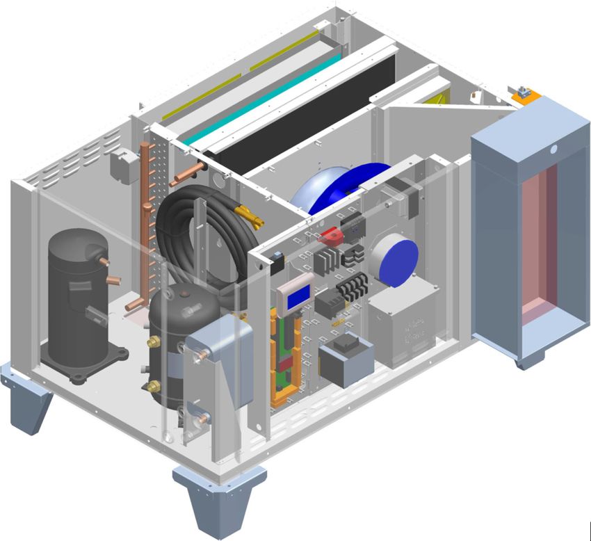
September 2021 29 PoolPak PCP Series – Indoor OMMCompressor Circuit Operation
Piping schematic for compressor circuit is shown on Pic. E.1.
When a demand requires the compressor to operate, the following sequence occurs:
Once blower operation, related safeties and timers are confirmed by the control system, the pump down
solenoid valve opens and once pressure stabilizes, the compressor starts.
Based on the premise air temperature, the refrigeration reheat and/or AC solenoid valve opens, allowing
refrigerant to flow through the respective condenser:
o if more heat is required by the room air, the reheat solenoid valve opens (heat is rejected to the
premise); if more cooling is required by the room air, the AC solenoid valve opens (heat is rejected
outdoors (via outdoor condenser or plate heat exchanger).
o Outdoor condenser or fluid cooler fan is engaged only if hot gas is diverted outdoors and compressor
pressure is higher than pre‐set level (see Outdoor Condenser and Fluid Cooler Operation below).
Dehumidifiers, equipped with pool water heating option, also engage the refrigeration pool water heating
solenoid valve to reject heat into the pool water, based on pool water temperature.
Once demand for the compressor’s operation is removed (respective call is satisfied), the pump down solenoid
valve closes; once the compressor suction pressure reaches the pre‐set pressure, the compressor stops.
Pic. E.1
Note. Suction accumulator is not typically found on 2‐7 ton models.
Outdoor Air Condenser and Fluid Cooler Operation.
Based on the type of the outdoor condenser or fluid cooler fans’ type (two‐speed fans or EC‐type/modulating
fans), respective signal(s) are sent by control system to engage said fan(s): for two‐speed fans ‐ on/off signals
(switching speeds, based on compressor head pressure level), for EC‐type fans ‐ variable 0‐10VDC signal
(proportional to the compressor head pressure level). Refer to the fans’ type and wiring diagram if/when needed.
If the fluid cooler is equipped with the built‐in pump package (to establish cooling fluid flow between dehumidifier
and the fluid cooler or to serve as additional/booster pump), the said pump is also engaged along with fluid cooler
fans – pump would stay engaged while fans are engaged (regardless of the fans’ speed).
PoolPak PCP Series – Indoor OMM 30 September 2021Interface and Communication
Touch Display Operator Panel
The Touch Display Operator Panel (OP), shown on Pic. F.1, is used as a main interface between the dehumidifier
and operator. The same OP can be located in the dehumidifier main electric panel (default; used as a local OP) or
installed remotely from the dehumidifier
NOTE: length of CAT5 or CAT6 cable, between remote OP and the dehumidifier MUST NOT exceed 1000’!
Touch Display OP allows to:
Access Touch Display Menus
View dehumidifier current operational
statuses (Touch Display Communication,
Alarms, dehumidifier operational calls, etc.)
View controlled parameters’ values (premise
air temperature, humidity and, if applicable,
pool water temperature) and current date
and time.
Pic. F.1
Touch Display Menus:
Home Opens/returns to the home page
Logs Access to dehumidifier logs and log‐related features (Alarms, etc.)
User Access to user settings (Setpoints) and commands (Stop/Restart Dehumidifier, etc.)
Advanced Access to advanced settings and features
Help Context sensitive help presenting information related to the viewed page
Most common/basic maintenance tasks performed using Touch Display OP
Adjust Setpoint – in User menu: press the User button, then press the Setpoints button; select desired
parameter (room air temperature etc.) and enter the desired value. Press the Enter button to confirm the
entered value.
Stop/Restart Dehumidifier –– in User menu: press the User button, then press the System Restart button;
o To stop and restart dehumidifier, press the System Restart button
o To reboot Touch Display OP, press the Restart Display button
Review Alarm records –– done via the Logs menu: press the Logs button, then press the Alarm Log button.
Unlock device/dehumidifier, stopped and currently locked out on the alarm –– done via Logs menu: press
the Logs button, then press the Current Alarms button; press the Clear button next to the respective alarm
(the alarm that’s locked out the device or entire dehumidifier).
For detailed information on TouchDisplay OP refer to CommandPak® Control System Touch Display User Manual,
provided with the dehumidifier (or contact factory to obtain a copy).
September 2021 31 PoolPak PCP Series – Indoor OMMAlarms
If the dehumidifier control system detects abnormal or unsafe for further operation situation, it issues Alarm
(notification of such situation accompanied by respective component or entire dehumidifier stoppage and/or
lockout) or Alert (notification of minor abnormal situation without any devices’ stoppage or lockout).
All alarms and alerts are recorded and can be viewed/cleared via the Touch Display OP:
Viewed: to facilitate troubleshooting and addressing abnormal situation
Cleared: to unlock stopped device or entire dehumidifier and allow for further operation
The table F.1 below lists the basic alarms with their descriptions and recommended initial troubleshooting.
Table F.1. Most Common Alarms/Alerts
Alarm Alarm Description Check
No Air No air flow (air flow switch fault – if air flow Check main blower operation and air flow
switch is installed) switch
Blower OL Main Blower overload/safety fault Check main blower operation and its LED
light blinking pattern.
Fire Fire/smoke detector fault – if detector is installed Check external fire/smoke
externally and connected to control board detector/system
Freeze Supply Air temperature is lower than Freezestat Check SA temperature readout, space
Setting (default: 45 F) heating system operation
Filter Alert, indicating that filter change timer has Clear the Filter alarm and cancel filter
lapsed – if timer is activated scheduler if not in use.
VM Voltage Monitor fault – power supply (phasing, Check Voltage Monitor info/status,
voltage etc.) is outside of pre‐set limits incoming power (voltage)
Compressor: Various compressor‐related alarms, relevant to: Check respective compressor‐related data
‐ HP1‐(X) ‐ Compressor high/discharge pressure; (pressure and temperature readouts),
‐ LP1‐(X) ‐ Compressor low/suction pressure; refrigerant level in the receiver’s sight
‐ SupHeat1 ‐ Compressor superheat/suction temperature; glasses, cleanliness of air‐side coils and air
‐ DisTemp1 filters.
Pool Water: Various compressor pool water heating‐related Unless the alarm occurred due to a known
Water(X)1, alarms indicating inadequate (too low/too high) water flow interruption (backwash, etc.),
Wtr(X)1 pool water flow and/or pool water temperature. check the pool water flow (pump, filters,
valves) and pool water temperatures.
HPRelief Alert, indicating that additional condensing No action required unless it’s
capacity is engaged (pool water heat exchanger accompanied by other (compressor‐
etc.) to prevent compressor high pressure from related) alarm or faulty situation.
rising too high.
Note that proper and regular maintenance (example: keeping air filters and air‐side coils clean) should
reduce the chances of abnormal operations, dehumidifier alarm‐related stoppages and downtime.
CAUTION! We recommend you have a qualified professional investigate and remedy all reoccurring
alarm‐related stoppages and lock‐outs. Continuous dehumidifier restarting (clearing alarms) without addressing
actual issues may result in equipment malfunction, premature wear, and failure.
For more details regarding alarms and alerts, refer to the Alarms Description information (available via Help
feature in Touch Display OP); contact factory if needed.
PoolPak PCP Series – Indoor OMM 32 September 2021Remote Communication
Although dehumidifier is designed to operate as a self‐controlled device (not requiring any external control),
communication between the dehumidifier and external control and monitoring systems is possible.
Virtual‐Tech
Virtual‐Tech is an online tool (also referred to as Web Monitor), that allows for remote communication to the
dehumidifier for various purposes such as monitoring, data collection, parameters adjustment, and notifications.
This feature is included with all dehumidifiers and is useful for maintenance teams and service providers (HVACR
technicians).
To establish Web Monitor communication, the dehumidifier must communicate with the factory server via the
Internet:
‐ Connect the dehumidifier to a local network switch, router or wireless AP device (providing connection to a
local network):
o Plug an Ethernet cable into the sub‐board Ethernet RJ‐45 jack (sub‐board, called Core Module, is
located on the main control board in the main electric panel) – see Pic. F.2.
Note: separate RJ‐45 jack (plastic, black) is mounted on the control board directly, for
TouchDisplay connection. Make sure to use the proper jack (metal‐surface one, located on
the sub‐board) for Web Monitor connection.
‐ Configure, as needed, local server and dehumidifier network settings.
BMS (Building Management System)
Communication to BMS can also be supported, depending on the
type of communication protocol said BMS utilizes.
The equipment control software supports most common of them
‐ different control software variation might be required to
support different BMS communication protocols. Contact
factory if necessary.
BACnet (Internet, IP). Communication is established via the
Ethernet cable (same method as Web Monitor).
BACnet and Web Monitor communication can be used
simultaneously.
LON or Modbus. Communication requires external wiring
between dehumidifier main control board and BMS terminal.
Wiring schematic is normally indicated on wiring diagram
(provided with dehumidifier).
If dehumidifier is equipped with LON communication option,
it’s normally provided with pre‐wired LonWorks Gateway for
communication purposes.
For more information about Web Monitor or BMS communication
set up (connection, configuration, access, point cutsheets, etc.) –
contact factory.
Pic. F.2
September 2021 33 PoolPak PCP Series – Indoor OMMBasic Maintenance
Although PoolPak equipment is built for minimal service downtime, periodic preventative maintenance is required
to ensure maximum reliability, safety, and operating efficiency.
WARNING! To ensure equipment longevity and proper and efficient operation, the dehumidifier and its
auxiliary systems and devices (outdoor condenser, fluid cooler, boiler package, etc.) must be maintained properly
and regularly. It is recommended to create a facility‐specific Routine Maintenance Program.
Failure to maintain the equipment properly and regularly could result in personal injury, equipment damage or
malfunction and will void the equipment warranty.
Maintenance and Safety
Only qualified/properly trained personnel should attempt to perform respective maintenance tasks.
When it is necessary to work with live electrical components, have a licensed electrician or other qualified
professional perform the required task.
Be properly trained and equipped. Some maintenance tasks may involve usage of power tools, chemicals, etc.
Refer to such tools and materials data (manuals, MSDS, etc.). Personnel performing such maintenance tasks
should be:
o Properly trained to handle such tools and materials safely
o Equipped with proper personal protective equipment
Turn the power off. Before performing any maintenance, disconnect all electrical power, including remote
disconnect, and discharge all energy storing devices (VFDs, etc.) before servicing. Follow proper lockout
procedures to ensure that power cannot be accidentally restored. Failure to follow provided safety warnings
and labels could result in serious injury or death.
Be aware of potential hazards. The Equipment contains moving mechanical parts, components under high
refrigerant pressures and surfaces with high temperatures. Before entering the dehumidifier and/or
performing any equipment maintenance work, make sure that all moving parts are stopped, and it is safe to
perform required task.
Maintenance Key Points
Here are some basic/key maintenance considerations, pertinent to all dehumidifiers and their auxiliary systems:
Dehumidifier in mechanical room. No chemicals should be stored in the same mechanical room where the
dehumidifier is installed. Chemical fumes/off‐gas can cause premature deterioration of the equipment.
o Store chemicals in a separate, well‐ventilated room.
Access to the Equipment. Ensure that the equipment is accessible (minimum clearances are maintained):
approaches to the dehumidifier are not restricted/limited with materials in mechanical room (indoor installed)
or with snow (outdoor installed dehumidifiers, OACC and OAFC).
“MUST DO” maintenance task. Although all other maintenance tasks are as important, these two maintenance
tasks are the most common and most helpful:
o Maintain clean air filters (return, outdoor air filters, etc.). Make sure to replace dirty filters regularly.
o Maintain clean air‐side coils (especially Outdoor Condenser or Fluid Cooler). Make sure to clean coils
regularly.
PoolPak PCP Series – Indoor OMM 34 September 2021 Pool Water Chemistry. Incorrect pool water chemistry (improper pH level or high concentration of chlorine,
sea salt or other corrosive additives etc.) can result in equipment premature wear or malfunction (let alone
poor air quality in the pool and potential health issues) and will void the equipment warranty. Refer to pool
water quality standards; contact factory as needed.
Routine Maintenance Program
Creating facility‐specific routine maintenance program and following it is vital to equipment longevity and efficient
operation.
The suggested general maintenance operations and their frequency/intervals, listed in the table M‐1 below, can be
used to create such a program. For more detailed maintenance recommendations related to specific components,
refer to the respective component manufacturer’s manual.
Table M.1. Recommended Maintenance Tasks and Intervals
Interval Maintenance Task
Weekly Observe the equipment for any changes in running conditions and unusual noise
Clean or replace air filters if clogged or dirty
Quarterly
Verify that all set‐points are correctly programmed as specified by the facility operator
Inspect and clean the drain pan(s)
Tighten electrical connections, if required
Check and tighten, if required, pool water hose clamps and sensor mounts
Inspect all airside coils (outdoor condenser, fluid cooler, dehumidifier coils – evaporator, etc.) for
Semi‐ dirt, cobweb build‐up, etc.; clean as needed
Annually
Check that the P‐trap is primed (filled with water). It is good practice to pour some water into the
drain pan to ensure that the P‐trap is primed and operational
Check the outdoor air louvres and dampers for accumulation of dust and clean as required
Inspect the equipment’s cabinet for corrosion. If any damage is found, clean and repaint the
affected surface with a rust‐resistant primer
Clean the fan wheel(s)
Check dampers operation (linkage/actuator is not loose, damper opens/closes properly etc.)
Inspect electrical components, wiring and insulation
Annually Rotate the fan wheel(s) and check for obstructions and rubbing
Check gasket condition on all doors to ensure an airtight seal
Check bolts on compressors, motor mounts, dehumidifier bases and coils and tighten if required
Verify that the airflow around the remote condenser or dry cooler is unobstructed
September 2021 35 PoolPak PCP Series – Indoor OMMSpecific Components Maintenance
Actual maintenance plan may vary from installation to installation, yet there are several key components from
maintenance prospective.
If needed, contact respective component manufacturer for additional maintenance information.
Filters
Ensure air filters are clean. Dirty air filters will negatively affect dehumidifier performance and lifetime
Frequency of filters replacement will vary based on air quality, dehumidifier usage, facility type, etc. Make
sure to replace filters regularly
Replace with filters of equivalent size and rating – refer to dehumidifier details (compartment stickers, etc.)
Insulation
Inspect dehumidifier insulation, exposed to airstream for microbial growth (i.e., mold). If there is evidence of
microbial growth on the interior insulation, the insulation should be removed and replaced prior to operating the
dehumidifier.
Air‐Side Coils
Warning: Hazardous chemicals! Cleaning agents can be highly acidic or alkaline. Handle all chemicals carefully
and use appropriate personal protective equipment (PPE). Refer to the cleaning agent manufacturer's Materials
Safety Data Sheet (MSDS) for safety and handling information. Failure to follow all safety instructions could
result in serious injury or death.
Warning: Hazardous pressures! Coils containing refrigerant under pressure must not be cleaned using a
solution over 150 ºF. Failure to follow these safety precautions could result in coil bursting, which could result
in serious injury or death.
To clean the coil
Disconnect all electrical power to the equipment
Use a soft brush to remove loose debris from the coil
Mix a high‐quality coil cleaning detergent with water according to the manufacturer's instructions
Clean coil according to suggested instructions
Thoroughly rinse both sides of the coil and the drain pan with, clean water
Straighten any coil fins that have been bent during the cleaning process
Confirm the drain line is clear
Replace all panels and parts and restore electrical power to the equipment
PoolPak PCP Series – Indoor OMM 36 September 2021Special Maintenance Tasks. Fluid Cooler Winterization.
Normally fluid coolers are used in the systems, filled with glycol mixture to prevent the system and the fluid cooler
from freezing and, potentially, rupturing, when exposed to temperatures below freezing point.
When fluid cooler is used with media that, when exposed to low temperatures, could freeze (water or lower‐
percentage glycol mixture), one way to protect the equipment is to drain it (also known as “winterization” of the
equipment).
Though fluid cooler itself is normally equipped with means to be drained properly/fully, it is recommended to have
same means in place for entire system (fluid cooler – piping – dehumidifier etc.):
Have each local high point of the system equipped with means to bleed the air (air bleeding valve etc.)
Have each local low point of the system equipped with means to drain the fluid.
CAUTION. Draining and re‐filling the fluid cooler must be performed by trained personnel, according to
proper field practice and system layout. Improper draining or re‐filling the system could lead to equipment
damage, malfunction, premature tear and ware and may void equipment warranty.
CAUTION. Ensuring that the fluid cooler and associated system(s) equipped with proper means of
draining, creating draining and re‐filling procedures as well as determining whether draining is warranted to
protect the equipment is outside of manufacturer’s scope and is a responsibility of installing contractor and local
maintenance team.
September 2021 37 PoolPak PCP Series – Indoor OMMYou can also read