DELL EMC POWERSCALE OneFS BEST PRACTICES
←
→
Page content transcription
If your browser does not render page correctly, please read the page content below
WHITE PAPER

 DELL EMC POWERSCALE
 OneFS BEST PRACTICES

                               Abstract
                               This paper describes best practices for installing, configuring and managing a
                               Dell EMC PowerScale cluster.

                               April 2021

1 | Dell EMC PowerScale OneFS Best Practices
© 2021 Dell Inc. or its subsidiaries.
Revisions
  Version              Date                      Comment

  1.0                  November 2017             Updated for OneFS 8.1.1

  2.0                  February 2019             Updated for OneFS 8.1.3

  3.0                  April 2019                Updated for OneFS 8.2

  4.0                  August 2019               Updated for OneFS 8.2.1

  5.0                  December 2019             Updated for OneFS 8.2.2

  6.0                  June 2020                 Updated for OneFS 9.0

  7.0                  September 2020            Updated for OneFS 9.1

  8.0                  April 2021                Updated for OneFS 9.2

Acknowledgements
This paper was produced by the following:

Author:              Nick Trimbee

The information in this publication is provided “as is.” Dell Inc. makes no representations or warranties of any kind with respect to the information in this
publication, and specifically disclaims implied warranties of merchantability or fitness for a particular purpose.

Use, copying, and distribution of any software described in this publication requires an applicable software license.

Copyright © Dell Inc. or its subsidiaries. All Rights Reserved. Dell, EMC, Dell EMC and other trademarks are trademarks of Dell Inc. or its subsidiaries.
Other trademarks may be trademarks of their respective owners.

2 | Dell EMC PowerScale OneFS Best Practices
© 2021 Dell Inc. or its subsidiaries.
TABLE OF CONTENTS

Contents
Intended Audience ............................................................................................................................... 5
   Data Layout Recommendations ......................................................................................................................................... 5
      Directory Structure and Layout ......................................................................................................................................................... 5
      File Limits ......................................................................................................................................................................................... 5
      OneFS Storage Efficiency ................................................................................................................................................................ 6

Node Hardware Recommendations ..................................................................................................... 6
      Cluster Pool Size and Limits ............................................................................................................................................................. 7
   OneFS Data Protection ...................................................................................................................................................... 7
      Small File Considerations ................................................................................................................................................................. 9

Data Tiering and Layout Recommendations ........................................................................................ 9
   SmartPools Data Tiering .................................................................................................................................................... 9
   Data Access and On-disk Layout ..................................................................................................................................... 12
      Attribute Optimization of Files and Directories ................................................................................................................................ 13
      Optimal usage of SSD space.......................................................................................................................................................... 15
   SSD Strategies ................................................................................................................................................................. 15
      OneFS Caching Recommendations ............................................................................................................................................... 16
   L3 Cache Best Practices .................................................................................................................................................. 17
      L3 Cache Considerations ............................................................................................................................................................... 18

Network Recommendations ............................................................................................................... 19
   External Front-end network .............................................................................................................................................. 19
   Front-end Connectivity Considerations ............................................................................................................................ 19
      Optimal Network Settings ............................................................................................................................................................... 20
      Network Isolation ............................................................................................................................................................................ 20
      Connection-balancing and Failover Policies ................................................................................................................................... 20
      Dynamic Failover ............................................................................................................................................................................ 21
      SmartConnect Pool Sizing .............................................................................................................................................................. 21
   SmartConnect Considerations ......................................................................................................................................... 21
Protocol Recommendations ............................................................................................................... 22
   NFS Considerations ......................................................................................................................................................... 22
      Client NFS Mount Settings ............................................................................................................................................................. 22
      Optimal Thread Count .................................................................................................................................................................... 23
      NFS Connection Count ................................................................................................................................................................... 23
      NFS Recommendations ................................................................................................................................................................. 23
   SMB Considerations ........................................................................................................................................................ 24
   SMB3 Multi-channel ......................................................................................................................................................... 24
New Cluster Best Practices................................................................................................................ 25

3 | Dell EMC PowerScale OneFS Best Practices
© 2021 Dell Inc. or its subsidiaries.
Data Availability and Protection Recommendations ........................................................................... 26
   Availability and recovery objectives ................................................................................................................................. 26
   Snapshot Considerations ................................................................................................................................................. 28
   Replication Considerations .............................................................................................................................................. 30
Data Management Recommendations ............................................................................................... 32
   Quota Best Practices ....................................................................................................................................................... 32
   Quota Considerations ...................................................................................................................................................... 33
   SmartDedupe Best Practices ........................................................................................................................................... 35
   SmartDedupe Considerations .......................................................................................................................................... 36
   In-line Data Reduction Best Practices ............................................................................................................................. 36
   In-line Data Reduction Best Considerations .................................................................................................................... 38
Data Immutability Recommendations ................................................................................................ 38
Permissions, Auth and Access Control Recommendations ............................................................... 41
   Access Zones Best Practices........................................................................................................................................... 41
Job Engine Recommendations .......................................................................................................... 41
   File System Maintenance Jobs ........................................................................................................................................ 41
   Feature Support Jobs ....................................................................................................................................................... 41
   User Action Jobs .............................................................................................................................................................. 41
   Job Engine Considerations .............................................................................................................................................. 43
Cluster Management Recommendations ........................................................................................... 44
   Cluster Capacity Management ......................................................................................................................................... 44
Best Practices Checklist .................................................................................................................... 44
Summary............................................................................................................................................ 44

4 | Dell EMC PowerScale OneFS Best Practices
© 2021 Dell Inc. or its subsidiaries.
Intended Audience
This paper presents best practices for deploying and managing a Dell EMC PowerScale cluster. It also offers configuration and tuning
recommendations to help achieve optimal performance for different workloads. This paper does not intend to provide a comprehensive
background to the OneFS architecture.
Please refer to the OneFS Technical Overview white paper for further details on the OneFS architecture.
The target audience for this white paper is anyone designing and deploying a Dell EMC PowerScale clustered storage environment. It
is assumed that the reader has an understanding and working knowledge of the OneFS components, architecture, commands and
features.
More information on OneFS commands and feature configuration is available in the OneFS Administration Guide.
Data Layout Recommendations
Directory Structure and Layout
In general, it is more efficient to create a deep directory hierarchy that consolidates files in balanced subdirectories than it is to spread
files out over a shallow subdirectory structure. Although the recommended maximum file limit per directory is one million, a best
practice is to constrain the number of files in any one directory to one hundred thousand. A maximum of 100,000 directories per
directory is also recommended. OneFS dynamically allocates new inodes from free file system blocks
The key for file and directory layout always revolves around balance. The goal should be for a directory tree structure and is file
contents to be as uniform as possible.
• Storing large numbers of files in a directory may affect enumeration and performance, but whether performance is affected
depends on workload, workflow, applications, tolerance for latency, and other factors. To better handle storing a large number of
files in a directory, use nodes that contain solid state drives (SSDs).
• Directory tree depth is limited to 509 directories and is determined by a maximum path length of 1,023 characters. However,
depths greater than 275 directories may affect system performance.
• The maximum number of open files is 315,000 per node.
• Hard links are limited to a maximum of 65,535 per cluster. However, setting the number of per-file hard links to higher than 1,000
can slow down snapshot operations and file deletions. This per-file value can be configured via the efs.ifm.max_links syscontrol.
The OneFS protocol daemons, such as the input-output daemon (lwio), may impose additional constraints on the number of files
that a node can have open. The protocol daemons typically impose such constraints because the kernel places limits on per-process
memory consumption.
File Count Limits
OneFS dynamically allocates new inodes from free file system blocks. The maximum number of possible inodes runs into the billions
and depends on the number and density of nodes in the cluster, as expressed by the following formulas:
4Kn drives: ((number of nodes in the cluster) * (node raw TB) * 1000^4 * .99) / (8192 * (number of inode mirrors))
512n drives: ((number of nodes in the cluster) * (node raw TB) * 1000^4 * .73) / (512 * (number of inode mirrors))
File Size Limits
The largest file size that OneFS currently supports is increased to 16TB in OneFS 8.2.2, up from a maximum of 4TB in prior releases.
In order to support files larger than 4TB, adequate space is required in all of a cluster’s disk pools in order to avoid a potential
performance impact. As such, the following hard requirements apply:
5 | Dell EMC PowerScale OneFS Best Practices
© 2021 Dell Inc. or its subsidiaries.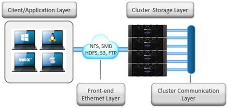
Large File Support Description
Requirement
Version A cluster must be running OneFS 8.2.2 in order to enable large file support.
Disk Pool A maximum sized file (16TB) plus protection can consume no more than 10% of any disk pool. This translates
to a minimum disk pool size of 160TB plus protection.
SyncIQ Policy All SyncIQ remote clusters must be running OneFS 8.2.2 and also satisfy the restrictions for minimum disk pool
size and SyncIQ policies.
After installing OneFS 8.2.2 on a cluster intended for large file support, the following CLI utility will verify that the cluster’s disk pools
and existing SyncIQ policies meet the above requirements:
# isi_large_file -c
Once the validation confirms that the cluster meets the requirements, the following CLI command is then run to enable large file
support:
# isi_large_file -e
Upon successfully enabling large file support, the ‘cluster full’ alert threshold is automatically lowered to 85% from the OneFS default of
95%. This is to ensure that adequate space is available for large file creation, repair, and restriping. Additionally, any
SyncIQ replication partners must also be running OneFS 8.2.2, adhere to the above minimum disk pool size, and have the large file
feature enabled.
Any disk pool management commands that violate the large file support requirements are not allowed. Once enabled, disk pools are
periodically checked for compliance and OneFS will alert if a disk pool fails to meet the minimum size requirement.
Be aware that, once enabled, large file support cannot be disabled on a cluster. This may impact future expansion planning for the
cluster and all of its SyncIQ replication partners.
Further information on OneFS limits and guidelines is available in the OneFS Technical Specifications guide.
OneFS Storage Efficiency
A typical data set consists of a mix of large and small files stored in a file system comprising a hierarchical directory structure. Usually,
around 30 percent of the data is active; 70 percent is inactive. Snapshots typically back up the data for short-term retention combined
with a long-term DR strategy, which frequently includes replication to a secondary cluster, and disk-to-disk or disk to tape NDMP
backups.
In this document, large files are considered as those which are 128KB or greater and small files are those less than 128KB. This is
significant because at 128KB and above, OneFS uses erasure coding (FEC) to parity protect a file, which results in high levels of
storage efficiency. Conversely, files less than 128KB in size are essentially mirrored, so have a larger on-disk footprint. Large file
efficiency via erasure coding offsets the penalty of mirroring of small files.
OneFS also provides additional storage efficiency via its native, post-process deduplication engine, SmartDedupe. Consider running
deduplication primarily on archive or DR clusters. If system resources allow, deduplication can also be run during off-hours against
lower-performance storage tiers or nodepools on primary storage.
Node Hardware Recommendations
Another key decision for cluster performance in an environment is the type and quantity of nodes deployed. Heterogeneous clusters
can be architected with a wide variety of node styles and capacities, in order to meet the needs of a varied data set and wide spectrum
of workloads. These node styles encompass several hardware generations and fall loosely into four main categories or tiers.
• Extreme performance (all-flash)
6 | Dell EMC PowerScale OneFS Best Practices
© 2021 Dell Inc. or its subsidiaries.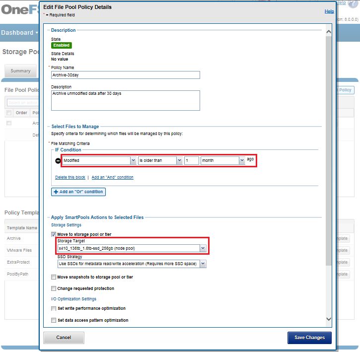
• Performance
• Hybrid/Utility
• Archive
The following table illustrates these tiers, and the associated Gen 6 hardware models:
Figure 1: PowerScale and Isilon Node Hardware Tiers
Prior to OneFS 8.0, the recommendation was for a maximum cluster size of around 64 nodes based on balancing customer experience
with the manageability of extra-large clusters, the risk profile associated with the size of the fault domain that represents for their
business, and the ease and simplicity of a single cluster. However, since then, OneFS 8 and later releases have seen considerable
backend network infrastructure enhancements removing this 64-node max recommendation and providing cluster stability up to the
current supported maximum of 252 nodes per cluster in OneFS 8.2 and later.
Cluster Pool Size and Limits
OneFS SmartPools allows you to define the value of the data within your workflows based on policies, and automatically aligns data to
the appropriate price/performance tier over time. Data movement is seamless, and with file-level granularity and control via automated
policies, manual control, or API interface, performance and layout, storage tier alignment, and protection settings can be tuned and
optimized with minimal impact to end-users.
OneFS Data Protection
A OneFS powered cluster eliminates much of the overhead that traditional storage systems consume. By not having RAID groups,
OneFS evenly distributes, or stripes, data among a cluster's nodes with layout algorithms that maximize storage efficiency and
performance. The system continuously reallocates data across the cluster, further maximizing space efficiency. At the same time,
OneFS protects data with forward error correction, or FEC—a highly efficient method of reliably protecting data.
• With respect to Gen6 hardware in particular, the best practice is to use the recommended ‘hybrid’ protection level, typically 2d:1n,
for cluster protection.
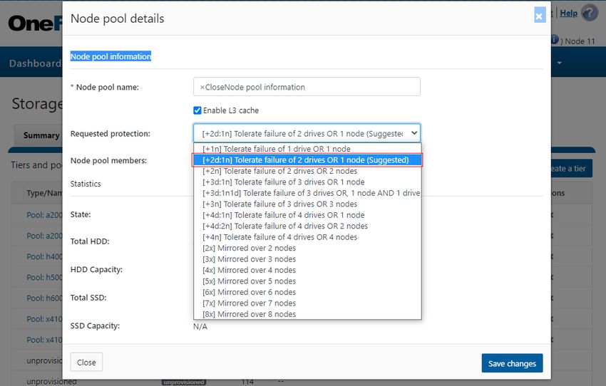
• The recommended protection level for a particular node pool is indicated as ‘Suggested’ in the list of requested protection levels.
7 | Dell EMC PowerScale OneFS Best Practices
© 2021 Dell Inc. or its subsidiaries.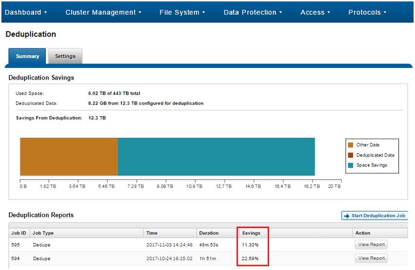
This can be viewed from the WebUI by navigating to Data Management > Storage Pools > SmartPools and selecting the desired nodepool or tier. For example: Figure 2: OneFS Suggested Protection Level The hybrid protection schemes are particularly useful for Isilon Gen6 chassis and other high-density node configurations, where the probability of multiple drives failing far surpasses that of an entire node failure. For all current Gen6 hardware configurations, the recommended protection levels are ‘+2d:1n’ or ‘+3d:1n1d’. In the unlikely event that multiple devices have simultaneously failed, such that the file is “beyond its protection level”, OneFS will re- protect everything possible and report errors on the individual files affected to the cluster’s logs. OneFS also provides a variety of mirroring options ranging from 2x to 8x, allowing from two to eight mirrors of the specified content. Metadata, for example, is mirrored at one level above FEC by default. For example, if a file is protected at +2n, its associated metadata object will be 4x mirrored. The full range of OneFS protection levels are summarized in the following table: Protection Level Description +1n Tolerate failure of 1 drive OR 1 node (Not Recommended) +2d:1n Tolerate failure of 2 drives OR 1 node +2n Tolerate failure of 2 drives OR 2 nodes +3d:1n Tolerate failure of 3 drives OR 1 node +3d:1n1d Tolerate failure of 3 drives OR 1 node AND 1 drive +3n Tolerate failure of 3 drives or 3 nodes +4d:1n Tolerate failure of 4 drives or 1 node 8 | Dell EMC PowerScale OneFS Best Practices © 2021 Dell Inc. or its subsidiaries.
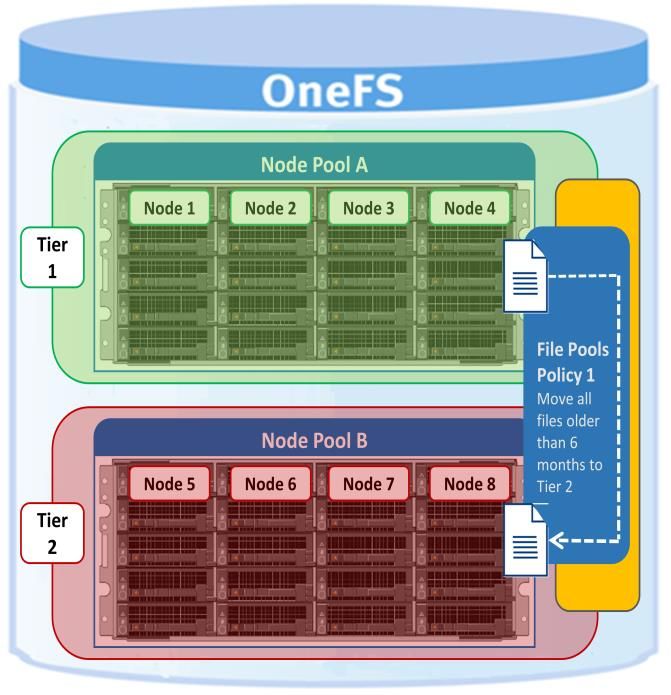
+4d:2n Tolerate failure of 4 drives or 2 nodes +4n Tolerate failure of 4 nodes 2x to 8x Mirrored over 2 to 8 nodes, depending on configuration Figure 3: OneFS protection levels Please refer to the OneFS Technical Overview white paper for further details on OneFS data protection levels. OneFS enables the protection policy to be modified in real time, while clients are attached and reading and writing data. Be aware, however, that increasing a cluster’s protection level may increase the amount of space consumed by the data on the cluster. OneFS also provides under-protection alerting for new cluster installations. If the cluster is under-protected, the cluster event logging system (CELOG) will generate alerts, warning the administrator of the protection deficiency and recommending a change to the appropriate protection level for that particular cluster’s configuration. Small File Considerations In practice, a OneFS powered cluster typically delivers between 75 and 90 percent space efficiency for a typical dataset. Given a dataset with a wide range of file sizes, it is the large files that dominate utilization, saving as much as 20 to 30 percent of capacity over traditional storage systems. Even when small files make up more than 90 percent of a dataset by file count, they consume only 10 percent or less of the capacity. As such, any inefficiencies in storing small files are overshadowed by the efficiencies in storing large files. And as a data set increases in size, a cluster moves closer to 80 percent efficiency. Data Tiering and Layout Recommendations SmartPools Data Tiering SmartPools enables a multi-tier architecture to be created using high performance nodes with SSD for performance tiers and high- capacity SATA-only nodes for the high-capacity archive tier. For example, a file pool policy could move files from the performance tier to a more cost-effective capacity-biased tier after the desired period of inactivity. 9 | Dell EMC PowerScale OneFS Best Practices © 2021 Dell Inc. or its subsidiaries.
Figure 4: SmartPools tiering.
The following screenshot shows the creation of an ‘archive’ file pool policy for colder data, which moves files that have not been
accessed for more than 30 days to a lower storage tier.

Figure 5: Creating a file pool policy

10 |Dell EMC PowerScale OneFS Best Practices
© 2021 Dell Inc. or its subsidiaries.
For optimal cluster performance, Dell EMC recommends observing the following OneFS SmartPools best practices:

•   It is not recommended to tier based on modify time (-mtime). Access time is the preferred tiering criteria, with an –atime value of 1
    day.

•   Ensure that cluster capacity utilization (HDD and SSD) remains below 90% on each pool.

•   If the cluster consists of more than one node type, direct the default file pool policy to write to the higher performing node pool.
    Data can then be classified and down-tiered as necessary.

•   A file pool policy can have three ‘OR’ disjunctions and each term joined by an ‘OR’ can contain at most five ‘AND’s.

•   The number of file pool policies should not exceed thirty. More than thirty policies may affect system performance.

•   Define a performance and protection profile for each tier and configure it accordingly.

•   File pool policy order precedence matters, as the policies are applied on first match basis (i.e., the first file pool policy to match the
    expression will be the applied policy).

•   When employing a deep archiving strategy, ensure that the performance pool is optimized for all directories and metadata and the
    archive tier is just for cold file storage as they age out. This can be configured by adding a ‘TYPE=FILE’ statement to the aging file
    pool policy rule(s) to only move files to the archive tier.

•   By default, the SmartPools job runs only once per day. If you create a file pool policy to be run at a higher frequency, ensure the
    SmartPools job is configured to run multiple times per day.

•   Enable SmartPools Virtual Hot Spares with a minimum of 10% space allocation. This ensures that there’s space available for data
    reconstruction and re-protection in the event of a drive or node failure, and generally helps guard against file system full issues.

•   Avoid creating hardlinks to files which will cause the file to match different file pool policies

•   If node pools are combined into tiers, the file pool rules should target the tiers rather than specific node pools within the tiers.

•   Avoid creating tiers that combine node pools both with and without SSDs.

•   The number of SmartPools tiers should not exceed 5. Although you can exceed the guideline of 5 tiers, doing so is not
    recommended because it might affect system performance.

•   Where possible, ensure that all nodes in a cluster have at least one SSD, including nearline and high-density nodes.

•   For performance workloads, SSD metadata read-write acceleration is recommended. The metadata read acceleration helps with
    getattr, access, and lookup operations while the write acceleration helps reduce latencies on create, delete, setattr, mkdir
    operations. Ensure that sufficient SSD capacity (6-10%) is available before turning on metadata-write acceleration.

•   Determine if metadata operations for a particular workload are biased towards reads, writes, or an even mix, and select the
    optimal SmartPools metadata strategy.

•   Avoid using OneFS Filesystem Explorer or the ‘isi set’ command to change file attributes, such as protection level, for a group of
    data. Instead use SmartPools file pool policies.

•   If SmartPools takes more than a day to run on OneFS 8.2 or later, or the cluster is already running the FSAnalyze job, consider
    scheduling the FilePolicy (and corresponding IndexUpdate job) to run daily and reducing the frequency of the SmartPools job to
    monthly. The following table provides a suggested job schedule when deploying FilePolicy:

11 |Dell EMC PowerScale OneFS Best Practices
© 2021 Dell Inc. or its subsidiaries.
Job Schedule Impact Priority
FilePolicy Every day at 22:00 LOW 6
IndexUpdate Every six hours, every day LOW 5
SmartPools Monthly – Sunday at 23:00 LOW 6
• If planning on using atime, be sure to enable Access Time Tracking as early as possible. The use of a 24-hour precision is
recommended to prevent performance problems.
Figure 6: Access time tracking configuration
More information on OneFS data tiering and file pool policies is available in the SmartPools white paper.
Data Access and On-disk Layout
Data Access Settings can be configured at the pool (or even the single file) level to optimize data access for the type of application
accessing it. Data can be optimized for Concurrent, Streaming or Random access. Each one of these settings changes how data is
laid out on disk and how it is cached.
Data Access Setting Description On-disk Layout Caching
Concurrency Optimizes for current load on Stripes data across the Moderate prefetching
the cluster, featuring many minimum number of drives
simultaneous clients. This required to achieve the data
setting provides the best protection setting configured for
behavior for mixed workloads. the file.
Streaming Optimizes for high-speed Stripes data across a larger Aggressive prefetching
streaming of a single file, for number of devices.
example to enable very fast
reading with a single client.
Random Optimizes for unpredictable Stripes data across the Little to no prefetching
access to the file by performing minimum number of drives
almost no cache prefetching. required to achieve the data
protection setting configured for
the file.
12 |Dell EMC PowerScale OneFS Best Practices
© 2021 Dell Inc. or its subsidiaries.Figure 7: OneFS data access settings As the settings indicate, the ‘Random’ access setting performs little to no read-cache prefetching to avoid wasted disk access. This works best for workload with only small files (< 128KB) and large files with random small block accesses. Streaming access works best for sequentially read medium to large files. This access pattern uses aggressive prefetching to improve overall read throughput, and on disk layout spreads the file across a large number of disks to optimize access. Concurrency (the default setting for all file data) access is the middle ground with moderate prefetching. • Concurrency is the preferred access setting for mixed workloads. Attribute Optimization of Files and Directories The attributes of a particular directory or file can be viewed by running the following command and replacing data in the example with the name of a directory or file. The command’s output below, which shows the properties of a directory named ‘data’, has been truncated to aid readability: # isi get -D data POLICY W LEVEL PERFORMANCE COAL ENCODING FILE IADDRS default 4x/2 concurrency on N/A ./ , , , ct: 1459203780 rt: 0 ************************************************* * IFS inode: [ 1,36,268734976:512, 1,37,67406848:512, 2,37,269256704:512, 3,37,336369152:512 ] ************************************************* * Inode Version: 6 * Dir Version: 2 * Inode Revision: 6 * Inode Mirror Count: 4 * Recovered Flag: 0 * Restripe State: 0 * Link Count: 3 * Size: 54 * Mode: 040777 * Flags: 0xe0 * Stubbed: False * Physical Blocks: 0 * LIN: 1:0000:0004 * Logical Size: None * Shadow refs: 0 * Do not dedupe: 0 * Last Modified: 1461091982.785802190 * Last Inode Change: 1461091982.785802190 * Create Time: 1459203780.720209076 * Rename Time: 0 * Write Caching: Enabled * Parent Lin 2 * Parent Hash: 763857 * Snapshot IDs: None * Last Paint ID: 47 13 |Dell EMC PowerScale OneFS Best Practices © 2021 Dell Inc. or its subsidiaries.
* Domain IDs:          None
* LIN needs repair:    False
* Manually Manage:
*       Access         False
*       Protection     True
* Protection Policy: default
* Target Protection: 4x
* Disk pools:           policy any pool group ID -> data target x410_136tb_1.6tb-
ssd_256gb:32(32), metadata target x410_136tb_1.6tb-ssd_256gb:32(32)
* SSD Strategy:        metadata
* SSD Status:          complete
* Layout drive count: 0
* Access pattern: 0
* Data Width Device List:
* Meta Width Device List:
*
* File Data (78 bytes):
*    Metatree Depth: 1
* Dynamic Attributes (40 bytes):
        ATTRIBUTE                 OFFSET SIZE
        New file attribute        0      23
        Isilon flags v2           23     3
        Disk pool policy ID       26     5
        Last snapshot paint time 31      9
*************************************************

* NEW FILE ATTRIBUTES
* Access attributes: active
* Write Cache: on
* Access Pattern: concurrency
* At_r: 0
* Protection attributes: active
* Protection Policy: default
* Disk pools:          policy any pool group ID
* SSD Strategy:        metadata-write
*
*************************************************

Figure 8: File and directory attributes

Here is what some of these lines mean:

   OneFS command to display the file system properties of a directory or file.

    The directory’s data access pattern is set to concurrency
    Write caching (SmartCache) is turned on.

14 |Dell EMC PowerScale OneFS Best Practices
© 2021 Dell Inc. or its subsidiaries.
The SSD strategy is set to metadata-read.
Files that are added to the directory are governed by these settings, most of which can be changed by applying a file pool policy
to the directory.
Optimal usage of SSD space
SSD Strategies
In addition to traditional hard disk drives (HDDs), OneFS nodes can also contain a smaller quantity of flash memory-based solid-state
drives (SSDs), right up to all-flash nodes. There are a number of ways that SSDs can be utilized within a cluster.
OneFS SSD Strategies are configured on a per file pool basis. These strategies include:
• Metadata read acceleration: Creates a preferred mirror of file metadata on SSD and writes the rest of the metadata, plus all the
actual file data, to HDDs.
• Metadata read & write acceleration: Creates all the mirrors of a file’s metadata on SSD. Actual file data goes to HDDs.
• Avoid SSDs: Never uses SSDs; writes all associated file data and metadata to HDDs only. This strategy is used when there is
insufficient SSD storage and you wish to prioritize its utilization.
• Data on SSDs: All of a node pool’s data and metadata resides on SSD.
Any node pools comprised off all-flash F-series nodes will automatically store all data and metadata on SSD, since those nodes do
not contain any traditional hard disk drives.
The following SSD strategy decision tree explains the options available:
15 |Dell EMC PowerScale OneFS Best Practices
© 2021 Dell Inc. or its subsidiaries.Figure 9: SSD usage decision tree In all these cases, ensure that SSD capacity utilization remains below 90%. If snapshots are enabled on a cluster, use the SSD Strategy “Use SSDs for metadata read/write acceleration” to enable faster snapshots deletes. The SSD metadata write strategy will require 6-10% of a pool’s capacity on SSD to accommodate all the metadata mirrors. In order to configure a particular tier to be the default for both data and metadata, the default file pool policy requires the SSD strategy to be set to “Use SSDs for data & metadata”. More information on data tiering and management in OneFS is available in the SmartPools white paper. OneFS Caching Recommendations OneFS uses up to three levels of read cache, plus an NVRAM-backed write cache, or coalescer. These, and their high-level interaction, are illustrated in the following diagram. 16 |Dell EMC PowerScale OneFS Best Practices © 2021 Dell Inc. or its subsidiaries.
Figure 10: OneFS Caching Hierarchy
The first two types of read cache, level 1 (L1) and level 2 (L2), are memory (RAM) based, and analogous to the cache used in
processors (CPUs). These two cache layers are present in all storage nodes.

An optional third tier of read cache, called SmartFlash or Level 3 cache (L3), is also configurable on nodes that contain solid state
drives (SSDs). SmartFlash (L3 cache) is an eviction cache that is populated by L2 cache blocks as they are aged out from memory.

L3 Cache Best Practices
If using L3 cache, Dell EMC recommends the following best practices:

•   Use a small number (ideally no more than two) of large capacity SSDs rather than multiple small SSDs.

•   Use the appropriate capacity of SSD(s) that will fit your working data set. The isi_cache_stats utility can help to determine that on
    existing clusters. A useful general rule is to size L3 SSD capacity per node according to the following formula:

         L2 capacity + L3 capacity >= 150% of working set size.

•   While L3 cache can potentially use up to a 2:1 HDD to SSD ratio per node, use at most 2-3 SSDs for L3 per node.

•   Repeated random read workloads will typically benefit most from L3 cache via latency improvements.

•   Although not recommended, both L3 cache and Global Namespace Acceleration (GNA) are supported within the same cluster.

•   The same procedure is used for replacing failed L3 cache SSDs as for other storage drives. However, L3 cache SSDs do not
    require FlexProtect or AutoBalance to run post replacement, so it’s typically a much faster process.

•   For a legacy node pool using a SmartPools metadata-write strategy, don’t convert to L3 cache unless:

         1.   The SSDs are seriously underutilized.

         2.   The SSDs in the pool are oversubscribed and spilling over to hard disk.

         3.   Your primary concern is SSD longevity.

17 |Dell EMC PowerScale OneFS Best Practices
© 2021 Dell Inc. or its subsidiaries.
L3 Cache Considerations
When deploying L3 cache, the following considerations should be kept in mind:
• All the SSDs within a node pool can either be used for L3 cache, or for SmartPools data strategies (metadata-ro, metadata-rw,
data) – but not mixed L3/SmartPools usage.
• L3 cache is not applicable for nodes containing 16 or more SSDs, and all SSD node pools are not eligible for L3 cache
enablement.
• Enabling L3 cache on an existing nodepool with SSDs takes some time, since the data and metadata on the SSDs needs to be
evacuated to other drives before the SSDs can be formatted for caching. Conversely, disabling L3 cache is a very fast operation,
since no data needs to be moved and drive reformatting can begin right away.
• If you’re concerned about metadata being evicted from L3, you can either deploy more SSDs per node to accommodate a large
working set or disable L3 and stick with traditional SmartPools metadata acceleration (either metadata read-only or read-write) for
the particular nodepool.
• It is possible to have GNA and L3 in the same cluster (different nodepools), although some manual setup is required including a
SmartPools policy to avoid SSD storage on L3 nodepool. Note that L3 nodepool HDD space does count towards GNA limits
• All the SSDs in an L3 cache nodepool must be the same size.
• If an L3 cache SSD fails, OneFS does not need to run FlexProtect or AutoBalance jobs, like with a regular filesystem SSD.
However, after the failed SSD is replaced, some period of time will be needed before the cache is repopulated.
• All new nodepools containing SSD will have L3 cache enabled by default.
• Existing nodepools with SSD will not be modified to use L3 cache on upgrade.
• SSDs displace HDDs. More SSDs and fewer HDD spindles can impact streaming and concurrency performance towards total
capacity.
• The L3 cache is intentionally avoided for streaming reads during data prefetch operation. This keeps the streaming requests to the
spinning disks (HDDs), while utilizing the SSDs for the random IO.
• L3 cache nodepool hard drive space DOES NOT count in GNA SSD percentage calculations.
• In L3 cache, metadata is preferentially cached over data blocks.
• When a node reboots, there’s no automatic flushing of L2 blocks to L3 cache.
• Unlike HDDs and SSDs that are used for storage, when an SSD used for L3 cache fails, the drive state should immediately
change to REPLACE without a FlexProtect job running. An SSD drive used for L3 cache contains only cache data that does not
have to be protected by FlexProtect. After the drive state changes to REPLACE, you can pull and replace the failed SSD.
• Although there’s no percentage completion reporting shown when converting nodepools to use L3 cache, this can be estimated by
tracking SSD space usage throughout the job run. The Job impact policy of the FlexprotectPlus or SmartPools job, responsible for
the L3 conversion, can also be reprioritized to run faster or slower.
• Current and historical L3 cache statistics are reported by InsightIQ.
• For L3 cache, the isi_cache_stats prefetch statistics will always read zero, since it’s purely an eviction cache and does not utilize
data or metadata prefetch.
• L3 cache has a metadata only mode (as opposed to data and metadata) to support high-density archive storage nodes.
Further information is available in the OneFS SmartFlash white paper.
18 |Dell EMC PowerScale OneFS Best Practices
© 2021 Dell Inc. or its subsidiaries.Network Recommendations There are two separate network infrastructures associated with a Dell EMC PowerScale cluster: External Front-end network Clients connect to the cluster using Ethernet connections (1GbE, 10GbE or 40GbE) that are available on all nodes. Because each node provides its own Ethernet ports, the amount of network bandwidth available to the cluster scales linearly with performance and capacity. The cluster supports standard network communication protocols to a customer network, including NFS, SMB, HTTP, FTP, HDFS, and S3 object, plus full IPv4 and IPv6 support. Figure 11: Cluster networking architectural overview Front-end Connectivity Considerations For most workflows, the recommendation is to configure at least one front-end 10 or 40 Gb Ethernet connection per node to support the high levels of network utilization that take place. Archive nodes and cold data workloads are often fine with 1Gb Ethernet connections per node. A best practice is to bind multiple IP addresses to each node interface in a SmartConnect subnet pool. Generally, optimal balancing and failover is achieved when the number of addresses allocated to the subnet pool equals N * (N – 1), where N equals the number of node interfaces in the pool. For example, if a pool is configured with a total of five node interfaces, the optimal IP address allocation would total 20 IP addresses (5 * (5 – 1) = 20) to allocate four IP addresses to each node interface in the pool. For larger-scaled clusters, there is a practical number of IP addresses that is a good compromise between N * (N -1) approach and a single IP per node approach. Example: for a 35-node cluster, 34 IPs per node may not be necessary, depending on workflow. Assigning each workload or data store to a unique IP address enables OneFS SmartConnect to move each workload to one of the other interfaces, minimizing the additional work that a remaining node in the SmartConnect pool must absorb and ensuring that the workload is evenly distributed across all the other nodes in the pool. For a SmartConnect pool with four-node interfaces, using the N * (N – 1) model will result in three unique IP addresses being allocated to each node. A failure on one node interface will cause each of that interface’s three IP addresses to fail over to a different node in the pool. This ensuring that each of the three active interfaces remaining in the pool receives one IP address from the failed node interface. If client connections to that node were evenly balanced across its three IP addresses, SmartConnect distributes the workloads to the remaining pool members evenly. The largest allocation per cluster that Dell EMC recommends is a /23 subnet, or 510 usable addresses. There are VERY few cases that would require such a large IP allocation. 19 |Dell EMC PowerScale OneFS Best Practices © 2021 Dell Inc. or its subsidiaries.
Optimal Network Settings
Jumbo frames, where the maximum transmission unit (MTU) is set to 9000 bytes, yield slightly better throughput performance with
slightly less CPU usage than standard frames, where the MTU is set to 1500 bytes. For example, with 10 Gb Ethernet connections,
jumbo frames provide about 5 percent better throughput and about 1 percent less CPU usage.
More information is available in the Advanced Networking Fundamentals guide.
Network Isolation
OneFS provides the ability to optimize storage performance by designating zones to support specific workloads or subsets of clients.
Different network traffic types can be isolated on separate subnets using SmartConnect pools.
For large clusters, partitioning the cluster’s networking resources and allocate bandwidth to each workload minimizes the likelihood that
heavy traffic from one workload will affect network throughput for another. This is particularly true for SyncIQ replication and NDMP
backup traffic, which can definitely benefit from its own set of interfaces, separate from user and client IO load.
Many customers as a best practice create separate SmartConnect subnets for the following traffic isolation:
• Workflow separation.
• SyncIQ Replication.
• NDMP backup on target cluster.
• Service Subnet for cluster administration and management traffic.
• Different node types and performance profiles.
OneFS 8.0 and later include a new networking object as part of the support for multi-tenancy. Groupnets sit above subnets and
pools and allow separate Access Zones to contain distinct DNS settings.
Figure 12: OneFS network object hierarchy
Connection-balancing and Failover Policies
By default, OneFS SmartConnect balances connections among nodes by using a round-robin policy and a separate IP pool for each
subnet. A SmartConnect license adds advanced balancing policies to evenly distribute CPU usage, client connections, or throughput. It
also lets you define IP address pools to support multiple DNS zones in a subnet.
Load-balancing Policy General of Few Clients with Many Persistent Many Transitory NFS
Other Extensive Usage NFS & SMB Connections Automounts or
Connections (HTTP, FTP, S3) UNC Paths
20 |Dell EMC PowerScale OneFS Best Practices
© 2021 Dell Inc. or its subsidiaries.Round Robin ✓ ✓ ✓ ✓ ✓
Connection Count * ✓ ✓ ✓ ✓
CPU Utilization *
Network Throughput *
* Metrics are gathered every 5 seconds for CPU utilization and every 10 seconds for Connection Count and Network Throughput. In
cases where many connections are created at the same time, these metrics may not be accurate, creating an imbalance across nodes.
Figure 13: Example usage scenarios and recommended balancing options
A ‘round robin’ load balancing strategy is the recommendation for both client connection balancing and IP failover.
Dynamic Failover
SmartConnect supports IP failover to provide continuous access to data when hardware or a network path fails. Dynamic failover is
recommended for high availability workloads on SmartConnect subnets that handle traffic from NFS clients.
For optimal network performance, observe the following SmartConnect best practices:
• Do not mix interface types (40Gb / 10Gb / 1Gb) in the same SmartConnect Pool
• Do not mix node types with different performance profiles (for example, Isilon H600 and A200 interfaces).
• Use the ‘round-robin’ SmartConnect Client Connection Balancing and IP-failover policies.
SmartConnect Pool Sizing
To evenly distribute connections and optimize performance, the recommendation is to size SmartConnect for the expected number of
connections and for the anticipated overall throughput likely to be generated. The sizing factors for a pool include:
• The total number of active client connections expected to use the pool’s bandwidth at any time.
• Expected aggregate throughput that the pool needs to deliver.
• The minimum performance and throughput requirements in case an interface fails.
Since OneFS is a single volume, fully distributed file system, a client can access all the files and associated metadata that are stored on
the cluster, regardless of the type of node a client connects to or the node pool on which the data resides. For example, data stored for
performance reasons on a pool of all-flash nodes can be mounted and accessed by connecting to an archive node in the same cluster.
The different types of platform nodes, however, deliver different levels of performance.
To avoid unnecessary network latency under most circumstances, the recommendation is to configure SmartConnect subnets such that
client connections are to the same physical pool of nodes on which the data resides. In other words, if a workload’s data lives on a pool
of F-series nodes for performance reasons, the clients that work with that data should mount the cluster through a pool that includes the
same F-series nodes that host the data.
SmartConnect Considerations
Keep in mind the following networking and name server considerations:
• Minimize disruption by suspending nodes in preparation for planned maintenance and resuming them after maintenance is
complete
21 |Dell EMC PowerScale OneFS Best Practices
© 2021 Dell Inc. or its subsidiaries.• If running OneFS 8.0 or later, leverage the groupnet feature to enhance multi-tenancy and DNS delegation, where desirable.
• Ensure traffic flows through the right interface by tracing routes. Leverage OneFS Source-Based Routing (SBR) feature to keep
traffic on desired paths.
• If you have firewalls, ensure that the appropriate ports are open. For example, for the DNS service, if you open UDP port 53,
ensure that TCP port 53 is also open.
• The client never sends a DNS request directly to the cluster. Instead, the site nameservers handle DNS requests from clients and
route the requests appropriately.
• In order to successfully distribute IP addresses, the OneFS SmartConnect DNS delegation server answers DNS queries with a
time-to-live (TTL) of 0 so that the answer is not cached. Certain DNS servers (particularly Windows DNS Servers) will fix the value
to one second. If you have many clients requesting an address within the same second, this will cause all of them to receive the
same address. If you encounter this problem, you may need to use a different DNS server, such as BIND.
• Certain clients perform DNS caching and might not connect to the node with the lowest load if they make multiple connections
within the lifetime of the cached address.
• The site DNS servers must be able to communicate with the node that is currently hosting the SmartConnect service. This is the
node with the lowest logical node number (LNN) with an active interface in the subnet that contains the SSIP address. This
behavior cannot be modified.
• Connection policies other than round robin are sampled every 10 seconds. The CPU policy is sampled every 5 seconds. If multiple
requests are received during the same sampling interval, SmartConnect will attempt to balance these connections by estimating or
measuring the additional load.
Further information is available in the OneFS SmartConnect white paper.
Protocol Recommendations
NFS Considerations
NFSv3 is the ubiquitous protocol for clients accessing storage. This is due to the maturity of the protocol version, ease of
implementation, and wide availability of client and server stacks.
There are some useful configuration settings to keep in mind when using a OneFS powered cluster with NFS clients in a performance-
oriented environment:
Client NFS Mount Settings
For NFS3 and NFS4, the maximum read and write sizes (rsize and wsize) are 1 MB. When you mount NFS exports from a cluster, a
larger read and write size for remote procedure calls can improve throughput. The default read size in OneFS is 128 KB. An NFS client
uses the largest supported size by default. Setting the value too small on a client overrides the default value and can undermine
performance.
For performance workloads, the recommendation is to avoid explicitly setting NFS rsize or wsize parameters on NFS clients when
mounting a cluster’s NFS exports directly, or via the automounter. Instead, for NFSv3 clients, use the following mount parameters:
mount -vers=3,rw,tcp,hard,intr,retry=2,retrans=5,timeo=600
For NFS clients that support it, the READDIRPLUS call can improve performance by ‘prefetching’ file handle, attribute information,
and directory entries – plus information to allow the client to request additional directory entries in a subsequent readdirplus
transaction. This relieves the client from having to query the server for that information separately for each entry.
22 |Dell EMC PowerScale OneFS Best Practices
© 2021 Dell Inc. or its subsidiaries.For an environment with a high file count, the readdirplus prefetch can be configured to a value higher than the default value of 10. For
a low file count environment, you can experiment with setting it lower than the default.
Another recommendation for performance NFS workflows is to use asynchronous (async) mounts from the client. Conversely, using
sync as a client mount option makes all write operations synchronous, usually resulting in poor write performance. Sync mounts should
be used only when a client program relies on synchronous writes without specifying them.
Optimal Thread Count
The number of threads used by the OneFS NFS server is dynamically allocated and auto-tuning and is dependent on the amount of
available RAM.
NFS Connection Count
As a conservative best practice, active NFS v3 or v4 connections should be kept under 1,000, where possible. Although no maximum
limit for NFS connections has been established, the number of available TCP sockets can limit the number of NFS connections. The
number of connections that a node can process depends on the ratio of active-to-idle connections as well as the resources available to
process the sessions. Monitoring the number of NFS connections to each node helps prevent overloading a node with connections.
NFS Recommendations
The recommended limit for NFS exports per cluster is 40,000. To maximize performance, configure NFS exports for asynchronous
commit.
For larger NFS environments consider the following:
• Use 10 or 40 Gb Ethernet whenever available
• Consider aggregating client interfaces using LACP.
• Where possible, use Jumbo frames (MTU 9000) to increase network payload.
• Use SmartConnect load-balancing, typically with a round-robin balancing policy.
• Optimize mount point organization.
• Consider using NFS netgroups for large, complex NFS environments
NFS over RDMA
OneFS 9.2 introduces Remote Direct Memory Access support for applications and clients with NFS over RDMA, and allows
substantially higher throughput performance, especially for single connection and read intensive workloads - while also reducing both
cluster and client CPU utilization. OneFS 9.2 supports NFSv3 over RDMA by leveraging the ROCEv2 network protocol (also known as
Routable RoCE or RRoCE). New OneFS CLI and WebUI configuration options have been added, including global enablement, and IP
pool configuration, filtering and verification of RoCEv2 capable network interfaces.
NFS over RDMA is also available on all PowerScale and Isilon Gen6 nodes which contain Mellanox ConnectX network adapters on the
front end with either 25, 40, or 100 Gig Ethernet connectivity. The ‘isi network interfaces list’ CLI command can be used to easily
identify which of a cluster’s NICs support RDMA.
On the other side, the NFS clients will also need RoCEv2 capable NICs and drivers, and to be running RoCEv2
There also are several key considerations to keep in mind when using NFS over RDMA:
• The MTU should match on both the OneFS cluster and NFSv3 client.
• IP failover will not work from an interface that supports ROCEv2 to one that does not. So if you’re testing on a cluster where not all
NICs support RoCE, and you’re configuring failover, you’re advised to create a separate RDMA IP pool.
• It’s also recommended to place a router, or L3 Switch, between the OneFS cluster nodes and the RDMA clients, since the linux
NFS over RDMA stack tends not to handle Gratuitous ARP very gracefully.
• Priority flow control should be enabled on all the switch ports.
23 |Dell EMC PowerScale OneFS Best Practices
© 2021 Dell Inc. or its subsidiaries.You can also read