Deploying VMware Site Recovery Manager 5.1 with VMware vSphere 5.1 on Hitachi Virtual Storage Platform in a UCP Pro Environment - White Paper
←
→
Page content transcription
If your browser does not render page correctly, please read the page content below
Deploying VMware Site Recovery Manager
5.1 with VMware vSphere 5.1 on Hitachi
Virtual Storage Platform in a UCP Pro
Environment

         White Paper

         By UCP Engineering – Technology Team

         September 2012
Table of Contents
Introduction................................................................................................................................................................................................. 2
Tested Solution Components ..................................................................................................................................................................... 3
          Hardware Components .................................................................................................................................................................... 3
                    Hitachi Virtual Storage Platform ............................................................................................................................................ 4
                    Hitachi Compute Blade 500 .................................................................................................................................................. 4
                    Brocade Ethernet Network .................................................................................................................................................... 5
                    Brocade Fibre Channel Fabric .............................................................................................................................................. 5
          Software Components ..................................................................................................................................................................... 6
                    Hitachi Unified Compute Platform for VMware vSphere integrated solution ......................................................................... 7
                    Hitachi TrueCopy Heterogeneous Remote Replication Bundle............................................................................................. 7
                    Hitachi Universal Replicator .................................................................................................................................................. 7
                    Hitachi ShadowImage Heterogeneous Replication ............................................................................................................... 8
                    VMware vSphere 5.1 ............................................................................................................................................................ 8
                    VMware vCenter Site Recovery Manager 5.1 ....................................................................................................................... 8
Solution Implementation ............................................................................................................................................................................. 9
          Configure the Storage Area Network ............................................................................................................................................... 9
          Configure the Storage Replication Link ......................................................................................................................................... 12
                    Hitachi TrueCopy Remote Replication Bundle .................................................................................................................... 13
                    Hitachi Universal Replicator ................................................................................................................................................ 13
                    Creating Journal Groups for Hitachi Universal Replicator ................................................................................................... 14
          Configure Storage.......................................................................................................................................................................... 14
                    Create and Attach Datastore to Host via UCP .................................................................................................................... 15
                    Create LDEVs within the Management Pool (Journal Vol, & Command Device) ................................................................ 16
                    Add Volumes to Management Node HSDs ......................................................................................................................... 16
                    Create a Command Device ................................................................................................................................................. 16
          UCP Pro for VMware vSphere SRM environment ......................................................................................................................... 17
          Configure Command Control Interface (CCI) for Replication ......................................................................................................... 19
                    Install Command Control Interface ...................................................................................................................................... 19
                    Configure Command Devices ............................................................................................................................................. 20
                    Configure Remote Replication Using Command Control Interface ..................................................................................... 20
                    (Optional) Configure Local Replication Using Command Control Interface ........................................................................ 22
          Implement Storage Replication for Site Recovery Manager .......................................................................................................... 23
                    Enabling replication for TrueCopy Synchronous ................................................................................................................. 24
                    Enabling replication for Universal Replicator....................................................................................................................... 24
                    (Optional) Enabling replication for ShadowImage ............................................................................................................... 24
          Configure Storage Replication Adapter with VMware Site Recovery Manager .............................................................................. 24
          Other Implementation Actions ....................................................................................................................................................... 26
Configuration Files ................................................................................................................................................................................... 27
          Hitachi TrueCopy Remote Replication Bundle Files ...................................................................................................................... 27
          Hitachi Universal Replicator Files .................................................................................................................................................. 28
          Hitachi ShadowImage Heterogeneous Replication Files ............................................................................................................... 29
For More Information ................................................................................................................................................................................ 31

             i
ii
1
Introduction
When deploying a virtualized data center with Hitachi’s Unified Compute Platform Pro for VMware vSphere, there are several
benefits gained in IT infrastructures:
Pre-configured and pre-tested Converged Infrastructure solution
Integrated infrastructure management capabilities directly into vSphere client
Reduce operating expenses through automated UCP workflows to allow a data center to run more efficiently
Protect critical applications running on a converged infrastructure with features such as VMware High Availability, which
reduces planned and unplanned downtime
Expanding data centers across multiple locations provides an opportunity to increase these layers of protection beyond a
single data center.
VMware vCenter Site Recovery Manager is a business continuity and disaster recovery solution that integrates VMware
vSphere infrastructures with data replication on storage systems to protect large sites and business critical applications. It
does the following:
Provides centralized management of disaster recovery plans
Enables non-disruptive testing
Automates site recovery and migration processes
Using an automated and tested recovery plan, a production data center can do a disaster recovery failover in an organized
and proven manner.
Remote data replication is a key function in building out stable and reliable disaster recovery environments. Replicating data to
a remote secondary site represents the most effective insurance policy against a catastrophic failure. Although you can
perform data replication at the server level, you can perform data replication more effectively within the storage infrastructure.
Hitachi Virtual Storage Platform is an integral piece in building out a robust business continuity and disaster recovery solution.
VMware vCenter Site Recovery Manager integrates tightly with Hitachi Virtual Storage Platform using the Hitachi Storage
Replication Adapter. The advanced functions found in the Virtual Storage Platform fulfill the requirements of a virtual
infrastructure and provide reliable protection by managing data replication across data centers.
This paper's intended use is by IT administrators charged with the storage, deployment, or administration of Hitachi’s UCP Pro
platform. It assumes familiarity with storage area network (SAN)-based storage systems, VMware vSphere, Hitachi data
replication technologies, and common IT storage practices.
2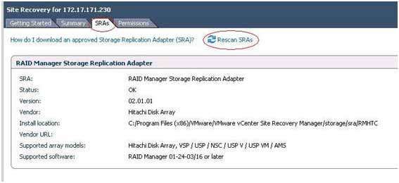
Tested Solution Components
This white paper describes how to implement a disaster recovery solution for a VMware virtualized infrastructure using Hitachi
hardware and software. Specifically, this solution uses Hitachi’s UCP Pro solution in local and remote “sites” which contain the
following:
Hardware Components
The following tables describe the hardware needed to deploy this solution. The UCP Pro solution for each site includes all of
the components listed.
Hardware Quantity Configuration Role
Hitachi Compute 1 8 x 520H B1 blades, Stateless ESXi Compute Nodes
Blade 500 chassis
Hitachi CR210 1u 2 Boot-from-SAN, Configured as a VMWare HA UCP Pro management
servers Cluster services/VMs
Brocade 5460 2 In-chassis Fibre Channel switches Edge switch (Core-Edge SAN
model)
Brocade 6510 2 Fibre channel switches Core Switch (Core-Edge SAN
model)
Three vFabs configured for;
o Compute resources
o Management resources
o Site-to-site replication
Brocade 6746 2 In-chassis Ethernet switches Access layer
Brocade 6720 2 Ethernet switches Aggregation layer
Table 1. Base UCP Pro Compute Rack
Hardware Quantity Configuration Role
Hitachi Virtual 1 16 x 8Gb/sec Fibre Channel ports Primary and remote storage
Storage Platform
(VSP) (4) – Management Host Ports
(8) – Compute Host Ports
(4) – Replication Ports
Table 2. Base UCP Pro Storage Rack
Virtual Machines for UCP management suite (running on CR210’s in HA Cluster)
o Vcenter Server 5.1
o SQL 2012
o UCP Utility Server (TFTP, Sylog, Etc…)
o UCP Director
o Hitachi Command Suite (HCSM & HDVM)
o SRM 5.1
The software for storage replication using the following:
o Hitachi Command Control Interface
o Hitachi TrueCopy® Remote Replication bundle
o Hitachi Universal Replicator
3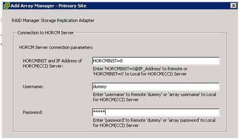
For purposes of this paper, we will refer to each UCP Pro instance as “Site A” and “Site B” respectively. The figure below
illustrates a high-level configuration of connectivity between two UCP “sites”. Detailed cabling designs within a base compute
rack, and its associated base storage rack can be found in the “UCP Hardware Assembly & Configuration Manual” ({official
doc number here}), while intra-site connectivity and configuration will be detailed later in this paper.
= 8Gb/sec FC
= 16Gb/sec FC ISL
= 10 Gb/sec IP
“Site A” LAN/WAN “Site B”
Figure 1 – UCP Site-to-site
Hitachi Virtual Storage Platform
Representing Hitachi’s flagship storage platform and an integral part of UCP Pro’s converged infrastructure, the Virtual
Storage Platform is the first 3D scaling storage platform designed for all data types. Its storage architecture flexibly adapts for
performance, capacity, and multi-vendor storage. Combined with the unique Hitachi Command Suite management platform, it
transforms the data center.
Scale Up — Meet increasing demands by dynamically adding processors, connectivity, and capacity in a single unit.
Provide the highest performance for both open and mainframe environments.
Scale Out — Meet multiple demands by dynamically combining multiple units into a single logical system with shared
resources. Support increased demand in virtualized server environments. Ensure safe multi-tenancy and quality of service
through partitioning of cache and ports.
Scale Deep — Extend storage value by virtualizing new and existing external storage systems dynamically. Extend the
advanced functions of Hitachi Virtual Storage Platform to multivendor storage. Offload less demanding data to external
tiers to save costs and to optimize the availability of tier one resources.
For more information, see Hitachi Virtual Storage Platform on the Hitachi Data Systems website.
Hitachi Compute Blade 500
Hitachi Compute Blade 500, an enterprise-class blade server platform, is a key component of the UCP Pro converged
infrastructure. It features the following:
High VM-to-blade density ratio making it an ideal virtualization platform
Latest Intel Xeon processors for state-of-the-art performance
Configuration flexibility
Eco-friendly power-saving capabilities
4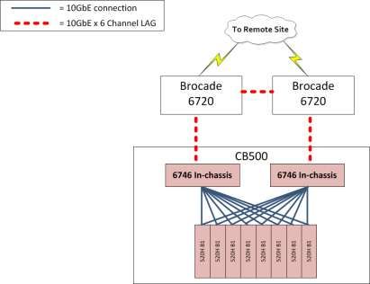
For more information, see Hitachi Compute Blade Family on the Hitachi Data Systems website.
Brocade Ethernet Network
UCP Pro’s converged infrastructure builds upon Brocade® and Hitachi Data Systems partnership to deliver key
networking and data center solutions.
The Ethernet infrastructure that is implemented in the UCP Pro converged infrastructure is designed to deliver high I/O
throughput of a 10GbE network while providing full redundancy for IP traffic.
Brocade VDX 6720 is a high-performance, ultra-low latency wire-speed 10 Gigabit Ethernet (GbE) fixed configuration
switch. The Brocade VDX 6720 is an ideal platform for a variety of Top-of-Rack (ToR) fabric deployments. Within the
UCP Pro base compute rack, there are two 6720’s configured as aggregation layer switches.
Brocade VDX 6746 is an OEM, ultra-low latency wire-speed 10 Gigabit Ethernet (GbE) in-chassis switch. For each CB
500 Compute Chassis, there are two 6746’s that are implemented as access layer switches and connected to the 6720 at
the top of the rack of the UCP Pro base compute rack.
The figure below shows the connections between;
The blades in the chassis and the 6746 in-chassis switches,
The 6746 in-chassis switches and the 6720’s
The Link Aggregation Groups (LAG) between to the 6720’s.
The uplink LAG to the customer network/remote site (i.e. “Site B”)
Figure 2 – UCP Ethernet connectivity
Brocade Fibre Channel Fabric
The Fibre channel infrastructure that is implemented in the UCP Pro converged infrastructure follows Hitachi and Brocade best
practices, and offers redundancy within the fabric, and multiple paths between host and volume for maximum throughput and
availability.
The Brocade 6510 fibre channel switch meets the demands of hyper-scale, private cloud storage environments by
delivering market-leading 16 Gbps Fibre Channel technology and capabilities that support highly virtualized environments.
The Brocade 5460 in-chassis fibre channel switch is an OEM developed switch based on the popular 5000-series FC
switch line.
5The figure below shows the connections between;
The blades in the chassis and the 5460 in-chassis switches,
The 5460 in-chassis switches and the 6510’s
The Storage Array Ports to the 6510’s.
The CR210 management nodes to the 6510’s
Figure 3 – Fibre channel connectivity
Software Components
The table below lists the software needed to deploy this solution.
Software Version
Hitachi UCP Pro (major components listed below)
VMware vCenter 5.1 build 799731
VMware vSphere ESXi 51 build 799733
UCP Director 2.0.0 build 1711
Hitachi Device Manager 7.3.1-02
Hitachi Compute Server Manager 7.3.0-02
6VMware Site Recovery Manager 5.1 build 820150
Hitachi Storage Replication Adapter 02.01.3
Hitachi Command Control Interface 01-28-03/05
Note: Ver. 01-24/03/13 or later is required
Hitachi Storage Navigator Microcode dependent
Hitachi TrueCopy Remote Replication bundle Licensed feature available with Hitachi Virtual Storage Platform
Hitachi Universal Replicator Licensed feature available with Hitachi Virtual Storage Platform
Hitachi ShadowImage® Heterogeneous Replication Licensed feature available with Hitachi Virtual Storage Platform
Table 2. Solution Software
Hitachi Unified Compute Platform for VMware vSphere integrated solution
Hitachi Unified Compute Platform Pro for VMware vSphere (UCP Pro for VMware vSphere) centralizes and automates the
management of servers, storage and networking components as business resource pools. Its comprehensive and simplified
management significantly reduces time to value and operational costs for even the most demanding applications. UCP Pro for
VMware vSphere’s deep integration into vSphere and vCenter enables faster deployment of cloud infrastructure and efficient
resource allocation. It also supports simple automation and orchestration for streamlined infrastructure management.
UCP Pro for VMware vSphere is an exceptionally flexible, converged solution that simplifies deployment and management of
data centers and private cloud deployments through it’s integrated solution composed of storage, servers, networking tools
and software with comprehensive management.
UCP Pro for VMware vSphere is designed for maximum performance and utilization leveraging Hitachi best-in-class hardware
and software technology. The solution is pretested and preconfigured to each organization’s requirements, dramatically
reducing deployment time.
Hitachi TrueCopy Heterogeneous Remote Replication Bundle
For synchronous replication up to 190 miles (300 km) with WAN optimized controllers, Hitachi TrueCopy Heterogeneous
Remote Replication bundle provides a no-data-loss, rapid restart solution. Real-time copies are the same as the originals. This
reduces recovery time to minutes.
Synchronous replication provides very fast recovery time (low RTO) and good data currency (low RPO) between Hitachi Data
Systems storage systems.
For more information, see TrueCopy Synchronous Remote Replication Software on the Hitachi Data Systems website.
Hitachi Universal Replicator
Hitachi Universal Replicator for the Hitachi Virtual Storage Platform is an advanced technology for asynchronously replicating
data hosted on Virtual Storage Platform models.
Asynchronous replication maintains a remote copy of data without having a performance impact on the primary data. In
asynchronous replication, the system considers an I/O update operation complete when confirming the update at the primary
site.
The Hitachi Virtual Storage Platform manages the process of replicating the changes to the secondary site.
Hitachi Universal Replicator software uses disk-based journaling and an optimized replication engine to reduce resource
consumption and costs while increasing performance and operational resilience. The strengths of Hitachi Universal Replicator
are two key technical innovations: performance optimized, disk based journaling and a pull-style replication engine.
The following are the key characteristics of Universal Replicator:
Replication across any distance without significant negative effect on host performance — Hitachi Universal Replicator
has been successfully used in replication configurations that span thousands of miles.
7 No acknowledgement dependencies from secondary site — Hitachi Universal Replicator replicates to a remote site
without the performance impact of waiting to acknowledge each individual record. Instead, Hitachi Universal Replicator
manages the remote relationship at a controller level. During a disruption of communication to the remote unit or while
exceeding the capability of the replication circuit, Hitachi Universal Replicator retains replicated write data in local journals,
then updates the write data when the condition is corrected.
There is a potential for some data lag between remote and primary sites, particularly at longer distances. Manage the recovery
point objective with the configuration of the data communication lines. When I/O activity at the primary site exceeds the
capacity of the communication channel, the data is staged and moved to the secondary site in the same order as it was written
at the primary site.
Hitachi ShadowImage Heterogeneous Replication
Hitachi ShadowImage Heterogeneous Replication is a storage-based hardware solution that creates RAID-protected duplicate
volumes within Hitachi Virtual Storage Platform. ShadowImage Heterogeneous Replication primary volumes (PVOL) contain
the original data. Up to nine secondary volumes (S-VOL) can be created as copies.
On Hitachi Virtual Storage Platform, use ShadowImage Heterogeneous
Replication to implement clones, a full copy of the primary data. Each clone is available for use by secondary applications. The
unique value of working with a clone is that any operation on a clone has no effect on the primary data.
Detailed information on using Shadow Image Heterogeneous Replication is in Hitachi Command Control Interface User and
Reference Guide (MK-90RD7010).
VMware vSphere 5.1
VMware vSphere 5.1 is a virtualization platform that provides a data center infrastructure. It features Distributed Resource
Scheduler (DRS), high availability, and fault tolerance.
Use of the round robin multipathing policy in vSphere 5.1 distributes the load across multiple host bus adapters (HBAs) and
multiple storage ports. Use of DRS with Hitachi Dynamic Provisioning automatically distributes loads on the ESX host and
across the back end of the storage system.
VMware vSphere 5.1 has the following components:
ESXi 5.1 — This is a hypervisor that loads directly on a physical server. It partitions one physical machine into many
virtual machines that share hardware resources. UCP Pro utilizes VMWare’s Autodeploy feature to minimize footprint by
utilizing “Stateless ESXi” where the hypervisor is loaded directly into memory, and is not booted from disk.
vCenter Server — This allows management of the vSphere environment through a single user interface. With vCenter,
there are features available such as vMotion, Storage vMotion, Distributed Resource Scheduler, high availability, and fault
tolerance.
For more information, see the VMware vSphere website.
VMware vCenter Site Recovery Manager 5.1
VMware vCenter Site Recovery Manager 5.1 is a disaster recovery solution that helps to reduce planned and unplanned
downtime of a vSphere infrastructure. It enables automated site recovery and migration processes. This can leverage the built-
in vSphere Replication for hypervisor-based replication to cover a wide range of required recovery time and date currency.
This reference architecture focuses on using Site Recovery Manager with storage-based replication technologies such as
Hitachi TrueCopy Heterogeneous Remote Replication bundle and Hitachi Universal Replicator. This use provides centralized
management of recovery plans. Tight integration between storage arrays, VMware vCenter, VMware vCenter Site Recovery
Manager, and the Hitachi Storage Replication Adapter ensure a coordinated recovery for large, business critical environments.
For more information, see VMware vCenter Site Recovery Manager on the VMware website at
http://www.vmware.com/products/site-recovery-manager/resource.html#docs .
8Solution Implementation
Although we have detailed the configuration of two UCP Pro “sites” with Compute Blade 500 chassis that are fully populated
with all 8 blades, the following section will focus on demonstrating replication for a single host, however the steps and
concepts can be expanded to include all blades within the site.
Follow these steps to deploy this solution:
1. Configure the Storage Area Network for virtual fabric and replication links
2. Configure the Storage Replication Link
3. Configure Storage
4. Configure vSphere environment
5. Configure Command Control Interface (CCI) for Replication
6. Implement Storage Replication for Site Recovery Manager
Configure the Storage Area Network
The 6510 Fibre Channel switches are configured with virtual fabrics to segregate general compute host traffic from
management host traffic. In addition to the UCP Pro virtual fabrics, an additional virtual fabric is needed for the replication
links in this solution. The following diagram displays the virtual fabrics within the 6510 switches.
= 8Gb connection
= 16Gb x 2 Channel ISL
“Site A” “Site B”
Brocade Brocade
6510 6510
VSP VSP
Vfab 1 Vfab 1
CL1-A, CL2-A CL1-A, CL2-A
Vfab 128 Vfab 128
CL1-B, CL2-B, CL1-B, CL2-B,
CL5-B, CL6-B CL5-B, CL6-B
CL5-A, CL6-A Vfab 2 Vfab 2 CL5-A, CL6-A
CL7-A, CL8-A CL7-A, CL8-A
Vfab 2 Vfab 2
CL3-B, CL4-B, CL3-B, CL4-B,
CL7-B, CL8-B CL7-B, CL8-B
Vfab 128 Vfab 128
CL3-A, CL4-A CL3-A, CL4-A
Vfab 1 Vfab 1
Figure 4 - Virtual fabric connectivity
9Each server blade at the local and remote site uses dual-port Fibre Channel mezzanine cards. They connect internally to the
internal Fibre Channel switch modules located in the Hitachi Compute Blade 500 chassis as depicted earlier in figure 3.
Four inter-switch links from each internal Fibre Channel switch modules connect to a Brocade 6510. In turn, each Brocade
6510 switch connects to eight target ports on the Hitachi Virtual Storage Platform.
The Hitachi Virtual Storage Platform supports active-active multipath connectivity. UCP Best practices ensures that at least
four unique paths exist from the ESXi host to the storage system to maximize availability. The multipathing policy was set to
round robin in ESXi 5.1.
The tables below show the zoning configuration for the protected site and the recovery site.
Host Host HBA/Port Fabric Zone Name Storage
Port
Protected Site – HBA Port 0 6510 #1 Port0_Compute1_CL1B_VSP_10_20_90_66 CL1B
Compute1
vFab #128
Protected Site – HBA Port 0 6510 #1 Port0_ Compute1_CL2B_VSP_10_20_90_66 CL2B
Compute 1
vFab #128
Protected Site – HBA Port 1 6510 #2 Port1_ Compute1_CL3B_VSP_10_20_90_66 CL3B
Compute 1
vFab #128
Protected Site – HBA Port 1 6510 #2 Port1_ Compute1_CL4B_VSP_10_20_90_66 CL4B
Compute 1
vFab #128
Protected Site – HBA Port 0 6510 #1 Port0_Mgmt1_ CL1A_VSP_10_20_90_66 CL1A
Mgmt1
vFab #1
Protected Site – HBA Port 0 6510 #1 Port0_Mgmt1_ CL2A_VSP_10_20_90_66 CL2A
Mgmt1
vFab #1
Protected Site – HBA Port 1 6510 #2 Port1_Mgmt1_ CL3A_VSP_10_20_90_66 CL3A
Mgmt1
vFab #1
Protected Site – HBA Port 1 6510 #2 Port1_Mgmt1_ CL4A_VSP_10_20_90_66 CL4A
Mgmt1
vFab #1
Protected Site – HBA Port 0 6510 #1 Port0_Mgmt2_ CL1A_VSP_10_20_90_66 CL1A
Mgmt2
vFab #1
Protected Site – HBA Port 0 6510 #1 Port0_Mgmt2_ CL2A_VSP_10_20_90_66 CL2A
Mgmt2
vFab #1
Protected Site – HBA Port 1 6510 #2 Port1_Mgmt2_ CL3A_VSP_10_20_90_66 CL3A
Mgmt2
vFab #1
Protected Site – HBA Port 1 6510 #2 Port1_Mgmt2_ CL4A_VSP_10_20_90_66 CL4A
Mgmt2
vFab #1
Table 1 – Site A zoning, Management virtual fabric (1) & Compute virtual fabric (128)
10Host Host HBA/Port Fabric Zone Name Storag
e Port
Recovery Site – HBA Port 0 6510 #1 Port0_Compute1_CL1B_VSP_10_20_90_67 CL1B
Compute1
vFab #128
Recovery Site – HBA Port 0 6510 #1 Port0_ Compute1_CL2B_VSP_10_20_90_67 CL2B
Compute 1
vFab #128
Recovery Site – HBA Port 1 6510 #2 Port1_ Compute1_CL3B_VSP_10_20_90_67 CL3B
Compute 1
vFab #128
Recovery Site – HBA Port 1 6510 #2 Port1_ Compute1_CL4B_VSP_10_20_90_67 CL4B
Compute 1
vFab #128
Recovery Site – HBA Port 0 6510 #1 Port0_Mgmt1_ CL1A_VSP_10_20_90_67 CL1A
Mgmt1
vFab #1
Recovery Site – HBA Port 0 6510 #1 Port0_Mgmt1_ CL2A_VSP_10_20_90_67 CL2A
Mgmt1
vFab #1
Recovery Site – HBA Port 1 6510 #2 Port1_Mgmt1_ CL3A_VSP_10_20_90_67 CL3A
Mgmt1
vFab #1
Recovery Site – HBA Port 1 6510 #2 Port1_Mgmt1_ CL4A_VSP_10_20_90_67 CL4A
Mgmt1
vFab #1
Recovery Site – HBA Port 0 6510 #1 Port0_Mgmt2_ CL1A_VSP_10_20_90_67 CL1A
Mgmt2
vFab #1
Recovery Site – HBA Port 0 6510 #1 Port0_Mgmt2_ CL2A_VSP_10_20_90_67 CL2A
Mgmt2
vFab #1
Recovery Site – HBA Port 1 6510 #2 Port1_Mgmt2_ CL3A_VSP_10_20_90_67 CL3A
Mgmt2
vFab #1
Recovery Site – HBA Port 1 6510 #2 Port1_Mgmt2_ CL4A_VSP_10_20_90_67 CL4A
Mgmt2
vFab #1
Table 2 – Site B zoning, Management virtual fabric (1) & Compute virtual fabric (128)
In addition, replication requires dedicated Fibre Channel connections between storage systems at the local and the remote
site. For this solution, each Hitachi Virtual Storage Platform uses a total of two initiator ports and two RCU target ports.
The following table and diagram shows the storage replication paths and zoning between storage systems on each site.
11Storage System Storage Port Fabric Zone Name Storage System Storage Port
Protected Site - 5A - Initiator 6510 #1 (both VSP1_5A_VSP2_5A Recovery Site - 5A - RCU Target
VSP1 sites) VSP2
vFab #2
Protected Site - 6A - RCU 6510 #1 (both VSP1_6A_VSP2_6A Recovery Site - 6A - Initiator
VSP1 Target sites) VSP2
vFab #2
Protected Site - 7A - RCU 6510 #2 (both VSP1_7A_VSP2_7A Recovery Site - 7A - Initiator
VSP1 Target sites) VSP2
vFab #2
Protected Site - 8A - Initiator 6510 #2 (both VSP1_8A_VSP2_8A Recovery Site - 8A - RCU Target
VSP1 sites) VSP2
vFab #2
Table 3 – Virtual Fabric zoning for replication ports
VSP Site A VSP Site B
5A
5A
RCU
Initiator
Target
7A
7A
RCU
Initiator
Target
6A
6A
RCU
Initiator
Target
8A
8A
RCU
Initiator
Target
Figure 5 - Initiator/Target configuration
Configure the Storage Replication Link
Site Recovery Manager supports two types of replication technologies available with Hitachi Virtual Storage Platform. Choose
the storage replication technology based on the recovery point object (RPO) requirement, as shown in the table below.
12Table 4 – RPO Requirements
Requirement Replication Type Storage Replication Technology
Low RPO Synchronous remote replication Hitachi TrueCopy Heterogeneous Remote Replication Bundle
Flexible RPO Asynchronous remote replication Hitachi Universal Replicator
The following describes how to configure the storage replication link between the local and remote storage systems for the
respective replication technologies.
Hitachi TrueCopy Heterogeneous Remote Replication Bundle
Hitachi Universal Replicator
Creating Journal Groups for Hitachi Universal Replicator
Hitachi TrueCopy Remote Replication Bundle
This procedure assumes that zoning storage replication paths within your Fibre Channel fabric is complete. To create storage
replication links for Hitachi TrueCopy on Virtual Storage Platform using Hitachi Storage Navigator software, follow these steps:
1 From the Actions menu, point to Remote Copy, then point to TrueCopy, and then click RCU Operation.
2 Modify settings on the storage ports.
1 Click the Pen button in the top right area of the pane to enter Modify mode.
2 Click the Port option.
3 Right-click the storage ports to change the port attribute to Initiator or RCU Target, as appropriate. This solution uses
ports for Initiator and RCU Target as depicted above in figure 5.
4 Click the MCU&RCU option.
5 Click CU Free from the navigation tree. TrueCopy software selects the first available control unit to be the RCU.
6 Right-click the blank space on the right pane. A shortcut menu opens.
3 Add the RCU (Fibre) connections.
1 Click RCU Operation and then click Add RCU (Fibre) from the shortcut menu. The Add RCU (Fibre) dialog box
opens.
2 Provide the following information in the Add RCU (Fibre) dialog box:
1 Type the serial number for the remote storage system in S/N.
2 Click the LDKC of the remote storage system from the LDKC list.
3 Click 6 (VSP) from the Controller ID list.
4 Select the Default check box for the Path Group ID.
5 Click the local storage system port and its corresponding pair port in the MCU-RCU Path area. This solution uses
ports for Initiator and RCU Target as depicted above in figure 5.
3 Set options.
1 Click Option.
2 Type values in Minimum Paths, RIO MIH Time (sec.) and Round Trip Time (ms).
3 Click Set.
4 Accept the changes and complete the changes.
1 Click Apply. A confirmation dialog box opens.
2 Click OK to confirm applying the changes. Another confirmation dialog box opens.
3 Click OK.
Repeat these steps on the remote storage system to add an RCU (Fibre) connection for reverse replication. This is necessary
for VMware Site Recovery Manager to perform failback operations.
Hitachi Universal Replicator
This procedure assumes that zoning storage replication paths within your Fibre Channel fabric is complete. To create storage
replication links for Hitachi Universal Replicator on Virtual Storage Platform using Hitachi Storage Navigator software, follow
these steps:
1 From the Actions menu, point to Remote Copy, then point to Universal Replicator, and then click DKC Operation.
2 Modify settings on the storage ports.
1 Click the Pen button in the top right area of the pane to enter Modify mode.
2 Click the Port option.
3 Right-click the storage ports to change the port attribute to Initiator or RCU Target, as appropriate. This solution uses
ports for Initiator and RCU Target as depicted above in figure 4.
4 Click the DKC option. The LDKC navigation tree displays in the left pane.
5 Click LDKC#00 on the navigation tree.
136 Right-click the blank space on the left pane. A menu displays.
3 Add the DKC connections.
1 Click DKC Operation and then click Add DKC from the list. The Add DKC dialog box opens.
2 Provide the following information in the Add DKC dialog box:
1 Type the serial number for the remote storage system in S/N.
2 Click the LDKC of the remote storage system from the LDKC list.
3 Click 6 (VSP) from the Controller ID list.
4 Click the local storage system ports and its corresponding pair-port in the M-R path area.
3 Set options.
1 Click Option.
2 Type values in Minimum Paths and RIO MIH Times (sec).
3 Click Set.
4 Accept the changes and complete the changes.
1 Click Apply. A confirmation dialog box opens.
2 Click OK to confirm applying the changes. Another confirmation dialog box opens.
3 Click OK.
Repeat these steps on the remote storage system to add a DKC connection for reverse replication. This is necessary for
VMware Site Recovery Manager to perform failback operations.
Creating Journal Groups for Hitachi Universal Replicator
To create Hitachi Universal Replicator journal groups using Hitachi Storage Navigator, follow these steps on the local storage
system:
1 From the Actions menu, point to Remote Copy, then point to Universal Replicator, and then click Journal Operation.
2 Modify settings for the journals.
1 Click the Pen button in the top right area of the pane to enter Modify mode.
2 In the Journals tree, click to expand Free.
3 Select (highlight) a free journal group from Free. Details of the selected free journal group display in the right area.
4 Right-click the highlighted group in the right area, and then click Edit JNL VOLs from the shortcut menu. The Edit JNL
Volumes dialog box opens.
5 Populate the journal volumes.
1 Click the CU option.
2 From the menu on the right, click a CU. The Free Volumes pane populates.
6 Populate the journal volumes.
1 Select one or more volumes in the Free Volumes area. The Add button becomes available.
2 Click Add. The JNL Volumes area populates.
3 Save the changes.
1 Click Set and then click Apply. A confirmation dialog box opens.
2 Click Yes. A final confirmation opens.
3 Click OK.
Repeat these steps on the remote storage system to add a journal group.
Configure Storage
This is how to configure your storage for this solution using Hitachi Dynamic Provisioning on Hitachi Virtual Storage Platform.
The storage configuration for this solution includes the following:
Over provisioning
Wide striping
On-line expansion of dynamic provisioning pools
This solution uses a dynamic provisioning pool comprised of a single RAID group with eight 600 GB 10k RPM SAS drives in a
RAID-6 (6D+2P) configuration for each storage system. To increase performance and capacity needs of your virtual
environment, add more RAID groups to the dynamic provisioning pool.
Using a RAID-6 configuration lowers the risk of data loss or pool failure, which is a primary concern for virtual machines
protected by VMware Site Recovery Manager. Refer to Hitachi VSP Architecture guide for further details on Pool
configuration/benefits at: http://www.hds.com/assets/pdf/hitachi-architecture-guide-virtual-storage-platform.pdf .
The figure below shows the configuration for the dynamic provisioning pool on each storage system. For simplicity sake of this
paper, LDEV IDs are identical between sites.
14*Journal Volumes are only
required w/ Hitachi Universal
Replicator
Compute Pool Management Pool
Datastore Datastore Datastore
Jnl
1 2
Journal Vols*
CMD
RAID 6 (6+2) PG 1-1
RAID 6 (6+2) PG 1-3
RAID 6 (6+2) PG 1-5
Figure 6 – Pool and volume layout
The UCP Pro solution at each site will have the Management Pool and volumes pre-configured at the factory will contain 2
shared Datastores where the UCP Management virtual machines will be stored.
The compute pool will be configured to customer specifications onsite during the UCP system installation and configuration.
Upon completion of the UCP Pro system, the entire Server/Storage/Network stack will be in an operational state. For
purposes of this paper, this solution provisions 3 additional LDEVs to the VMware infrastructure at both sites for:
Datastore volume for compute host
Journal volume (only if HUR replication is used)
Command device (raw device mapping LUN to SRM/CCI server)
The creation and presentation of the LDEVs in Figure 3 on the storage system involves the following steps:
1 Create and Attach Datastore to Host via UCP
2 Manually Create and configure LDEVs in Compute pool
Journal Volume
Command Device
3 Attach Existing Volume to via UCP
The following describe in detail how to configure your storage for this solution.
Create and Attach Datastore to Host via UCP
This procedure creates the proper zoning within the Fibre Channel infrastructure, the volume, the host storage domain (HSD)
and the HSD mappings to the ESXi host HBA's World Wide Names (WWN). Host groups are then associated with LDEVs to
ensure access is isolated to the specified hosts.
To create and attach a datastore to a host using Hitachi UCP Pro, follow these steps:
151 From within vSphere client, right-click on the server that you want to add a volume to, and then click on the Configure
Host Storage link.
2 Select the Create New Volume option.
3 Click on the Next button.
4 On the Create New Volume step:
In the Name field, type a name to assign to the volume.
In the Disk Size field, type the total amount of space to use to create the volume in GB.
To format the volume as a datastore, select the Format as Datastore option. If this option is not selected, the
created volume will need to be formatted later before it can be used.
To manually select the array ports to use, select the Manually SelectArray Ports option, and then select the
appropriate ports for each fabric.
In the Pools table, select the pool to create the data store from.
5 Click on the Finish button.
6 If this is the first and only volume created within the array so far, the volume number (LDEV) should be 00:00:00. Verify
the LDEV ID, and if it is not 00:00:00, please record the actual value to be used later in the replication configuration.
Create LDEVs within the Management Pool (Journal Vol, & Command Device)
This procedure assumes completion of dynamic pool creation during UCP Pro initial configuration in your environment.
To create volumes that will be used for Journal Volume and Command Device, follow these steps on BOTH sites.
1 From the Actions menu, point to Logical Device and then click Create LDEVs. The Create LDEVs window opens.
2 From the Provisioning Type list, click Dynamic Provisioning.
3 From the Emulation Type list, click OPEN-V.
4 From the RAID Level list, click RAID-6 (6D+2P). These options allow you to filter the available RAID group volumes.
5 Select the pool options.
Click Select Pool. The Select Pool window opens.
Select the pool that represents the Management Pool (Pool 0) in the Available Pools area and click OK.
Type the capacity in LDEV Capacity and click a unit of measure from the list. This solution uses 5GB LDEVs for the
command device..
Type the number of LDEVs of the size in LDEV Capacity to create in Number of LDEVs.
In the LDEV Name area, type a prefix in Prefix and type an initial number in Initial Number.
6 Add the LDEVS.
Click Add. The Selected LDEVs pane populates.
Click Next.
Click Finish. The confirmation window for creating LDEVs opens.
Click Apply.
7 Repeat steps 1-6 for Journal Volume. Capacity for Journal volume in this solution is 50GB.
Add Volumes to Management Node HSDs
To add volumes to the management hosts that will be used for as Command Device, follow these steps on BOTH sites.
1 From the Actions menu, point to Logical Device and then click Add LUN Paths. The Add LUN Paths window opens.
2 From the Available LDEVs list, select the 5GB volume that will become the command device, and click the Add Button to
add it to the selected LDEVs list.
3 Click the Next button.
4 From the Available Host Groups list, select all 8 Management HSDs on ports (one for each Mgmt Host on CL1-A, CL2-A,
CL3-A, and CL4-A).
5 Click Add button to add Host Groups to the Selected Host Group list.
6 Click Next Button
7 Verify LUN paths, and click Finish button.
Create a Command Device
Create command devices at the local and remote sites. Verify that all the command devices are accessible by the ESXi hosts
through multiple I/O paths.
To create a command device using Hitachi Storage Navigator, follow these steps:
1 Create an LDEV in the Hitachi Dynamic Provisioning pool as described in "Create LDEVs within a Dynamic Provisioning
Pool " section and map to the created host groups.
2 Convert an LDEV to a command device in Storage Navigator by following these steps:
1 Select the LDEV from the Explorer > Logical Devices area.
162 From the Actions menu, point to Logical Device and then click Edit Command Devices.
3 In the Edit Command Devices window, click the Enable option.
4 Click Finish.
5 Click Apply.
UCP Pro for VMware vSphere SRM environment
This solution is built on a VMware HA model for both the UCP Management nodes, as well as the compute nodes. The use of
multiple ESXi hosts placed in a VMware HA cluster adds an additional layer of protection and redundancy for Virtual Machines
in a disaster recovery situation. The UCP management nodes are configured from the factory and during the onsite
configuration as depicted in the figure below.
Management Cluster Site A Management Cluster Site B
AD VM AD VM
VC5 VM SQL VM VC5 VM SQL VM
UCP VM UCP VM
HCS VM Util VM HCS VM Util VM
SiteA SiteA SiteB SiteB
ESXi01 ESXi02 ESXi01 ESXi02
Boot Boot Boot Boot
VSP SiteA VSP SiteB
00:FD:03 00:FD:03
Management Datastore1
Datastore1
00:FD:04
Management 00:FD:04
Datastore2 Datastore2
Figure 7 - Management Nodes
For this SRM/SRA solution, an additional set of components are required to be configured in the management cluster, and in
the pool for the management volumes on both sites.
1 Create virtual machine for SRM in cluster (Windows 2008 R2)
2 Command device created in management pool (see Create LDEVs within the Management Pool & Create a Command
Device above.
3 Command device attached to both management nodes (see Add Volumes to Management Node HSDs above).
4 Present the Command Device to the SRM VM as an RDM (Raw Device Mapping) volume.
5 Install SRM 5.1 on SRM VM
176 Install Hitachi SRA 2.01.3 on SRM VM
7 Install Hitachi Command Control Interface (CCI) on SRM VM
Once completed, the management cluster will look like the following figure:
Management Cluster Site A Management Cluster Site B
AD VM AD VM
VC5 VM SQL VM VC5 VM SQL VM
UCP VM UCP VM
HCS VM Util VM HCS VM Util VM
SRM VM SRM VM
SiteA SiteA SiteB SiteB
ESXi01 ESXi02 ESXi01 ESXi02
Boot Boot Boot Boot
VSP SiteA VSP SiteB
00:FD:03 00:FD:03
Management Datastore1
Datastore1
00:FD:04
Management 00:FD:04
Datastore2 Datastore2
00:FD:05 00:FD:05
CMD Dev CMD Dev
(as RDM) (as RDM)
Figure 8 - SRM VM w/Command Device
Looking at both site configurations with the Management environment, in conjunction with the compute environment and the
SRM protection group, the UCP Pro / SRM solution will look like the following:
18Management Cluster Site A Management Cluster Site B
AD VM AD VM
VC5 VM SQL VM VC5 VM SQL VM
UCP VM UCP VM
HCS VM Util VM HCS VM Util VM
SRM VM SRM VM
SiteA SiteA
Host 1 Host2
Boot Boot Boot Boot
VSP SiteA VSP SiteB
00:FD:03 00:FD:03
Management Datastore1
Datastore1
00:FD:04
Management 00:FD:04
Datastore2 Datastore2
00:FD:05 00:FD:05
CMD Dev CMD Dev
(as RDM) (as RDM)
Compute Host Site A Compute Host Site B
Protection Group
SiteA SiteB
Compute Compute
Datastore Datastore
TC or HUR replication Placeholder VM
VM
VM Placeholder VM
P-Vol S-Vol
Figure 9- End-to-end view of both sites
Configure Command Control Interface (CCI) for Replication
Hitachi TrueCopy and Hitachi Universal Replicator reside on storage systems at the primary site and the recovery site to
maintain the replication of data between P-VOLs and S-VOLs. Command control interface from Hitachi allows you to manage,
monitor, and control the Hitachi Universal Replicator process.
To configure the command control interface, follow these steps:
1 Install Command Control Interface
2 Configure Command Devices
3 Configure Remote Replication Using Command Control Interface
Repeat these steps on the primary site and the recovery site.
Install Command Control Interface
To install command control interface from Hitachi on the VMware Site Recovery Manager virtual machine, follow these steps:
1 Insert the installation media for command control interface into an I/O device (for example, CD-ROM) connected to the
virtual machine.
2 Run Setup.exe on the installation media. Follow the on-screen instructions to complete the installation.
193 Verify installation of the latest version of command control interface by typing the following command at a command
prompt from the Hitachi Open Remote Copy Manager installation directory (C:\HORCM\etc):
raidqry –h
The output looks something like the following:
Model: RAID-Manager/WindowsNT
Ver&Rev: 01-25-03/11
Usage : raidqry [options] for HORCM
Configure Command Devices
A command device is a dedicated logical volume on the storage system that functions as the interface to the storage system
from the host. The command device accepts a command from the host that it then executes on the storage system.
This procedure assumes the creation and mapping of a command device LDEV to the ESXi host using Hitachi Storage
Navigator.
To configure a command device, do the following:
1 From the VMware vSphere client, add the command device LDEV to the Site Recovery Manager virtual machine as a
physical RDM virtual disk.
2 Configure the command device in the guest operating system.
1 In Microsoft Windows 2008, from the Server Manager menu, point to Storage and then click Disk Management.
2 Right-click the RDM disk and click Online.
3 Right-click the RDM disk and click Initialize Disk.
4 Click MBR (Master Boot Record) as the partition style.
Do not install a volume. Define and configure the command device as a raw device with no file system and no mount
operation.
Configure Remote Replication Using Command Control Interface
There are two command control interface components. They reside on the following:
Storage System — Command devices and Hitachi TrueCopy or Hitachi Universal Replicator volumes (P-VOL and S-VOL)
Server — Hitachi Open Remote Copy Manager (HORCM), configuration definition files (for example, horcm0.conf), and
command control interface commands
The Hitachi Open Remote Copy Manager operates as a daemon process on the VMware Site Recovery Manager virtual
machines. When activated, Open Remote Copy Manager refers to the configuration definition files. The instance
communicates with the storage sub-system and remote servers.
Modify the services file in the C:\Windows\System32\drivers\etc folder to register the port name and number for each Open
Remote Copy Manager instance on each server. The port name entries for Open Remote Copy Manager in the services file
must be the same on all the servers. For example, if the service number for port name horcm0 is 11000/udp, the service
number for port name horcm1 must be 11001/udp in the services file on the Site Recovery Manager server at the local and the
remote site.
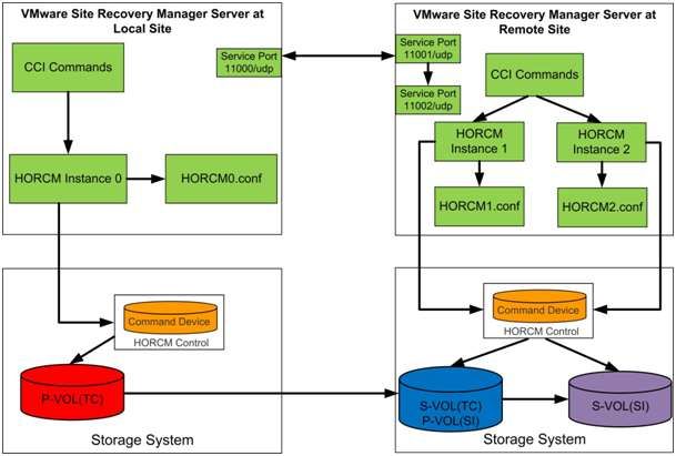
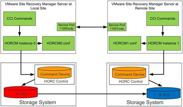
The figure below shows the two SRM server and their-HORCM instances configuration used with command control interface
to manage TrueCopy or Universal Replicator replication.
20Figure 10 - CCI/HORCM/Command device relationships Hitachi TrueCopy and Hitachi Universal Replicator require two instances of Open Remote Copy Manager to be operational. One instance manages the P-VOLs, The other instance manages the S-VOLs. The Open Remote Copy Manager configuration file defines the communication path and the logical units to be controlled. Each instance has its own configuration file saved in the C:\Windows directory. The content of the horcm0.conf file and the horcm1.conf file used to define a TrueCopy pair are available in “ Hitachi TrueCopy Remote Replication Bundle Files." The content of the horcm0.conf file and the horcm1.conf file used to define a Universal Replicator pair are available in "Hitachi Universal Replicator Files." After adding the port name entries and defining the configuration files, start the Hitachi Open Remote Copy Manager instance. At the command prompt, type the following: cd c:\HORCM\etc horcmstart.exe * An asterisk [*] is used in place of the instance number in the command. For example, for the server containing horcm0.conf, type horcmstart.exe 0. After executing the instructions described in the previous section at both sites, Open Remote Copy Manager instances should be running on the Site Recovery Manager servers at both sites. Verify the pair relationship by running the pairdisplay command from the horcm0 instance on the primary site's Site Recovery Manager server: pairdisplay.exe -g -IH -fcx Initially, the volumes are in simplex (SMPL) mode. The volumes are not paired and synchronized until running the paircreate command. The figures below show the pairdisplay.exe output of the TrueCopy pair defined in "Hitachi TrueCopy Remote Replication Bundle”, and the the Universal Replicator pair defined in "Hitachi Universal Replicator." 21
Figure 11 - Pairdisplay output of a Truecopy pair in simplex mode

Figure 12 - Pairdisplay output of an HUR pair in simplex mode
For more information about setting up the Open Remote Copy Manager instances and Open Remote Copy Manager
configuration file, see the Hitachi Command Control Interface (CCI) Users and Reference Guide that accompanies the Hitachi
Command Control Interface software.

(Optional) Configure Local Replication Using Command Control Interface
The recovery function of Site Recovery Manager is an optional feature that allows for non-disruptive failover testing.
Administrators can test failover without affecting the production remote replication. It requires an additional locally replicated
datastore at the recovery site's storage system. Follow the instructions in the Configure Storage section to create an LDEV
identical in size to the existing replicated volume.

Use Hitachi ShadowImage Heterogeneous Replication to create an in-system replication of the TrueCopy or Universal
Replicator's S-VOL to another LDEV. Similar to remote replication, Hitachi ShadowImage requires two instances of Hitachi
Open Remote Copy Manager (HORCM) to be operational. Both instances run from the Site Recovery Manager server on the
recovery site. Each instance has its own configuration file saved in the C:\Windows directory.

This solution modifies the TrueCopy horcm1.conf configuration file from " Hitachi TrueCopy Remote Replication Bundle Files"
to include a definition for the ShadowImage pair.

"Hitachi ShadowImage Heterogeneous Replication Files" has the content of the horcm1.conf and the horcm2.conf files used to
define a ShadowImage pair. In this example, the S-VOL for the TrueCopy pair acts as the P-VOL for the ShadowImage pair.

The figure below shows a two-server, three-HORCM instance configuration used with command control interface (CCI) to
manage TrueCopy with ShadowImage replication.

22
Figure 13 - Three HORCM instance configuration
After adding the port name entries and the defining the configuration files, start the Hitachi Open Remote Copy Manager
instance. At a command prompt, type the following:
cd c:\HORCM\etc
horcmstart.exe *

An asterisk [*] is substituted for the instance number in the command. For example, to start the remote server containing
horcm1.conf and horcm2.conf, type horcmstart.exe 1 2.

Verify the pair relationship by running the pairdisplay command from the horcm1 instance on the recovery site's Site Recovery
Manager server:
pairdisplay.exe -g  -IM -fcx

Initially, the volumes are in simplex (SMPL) mode. The volumes do not pair and synchronize until running the paircreate
command.

Figure 14 shows a pairdisplay output of the ShadowImage pair defined in "Hitachi ShadowImage Heterogeneous Replication ."

Figure 14 - Pairdisplay output for a ShadowImage pair in simplex mode

Implement Storage Replication for Site Recovery Manager
After defining volume pair relationships and starting the Hitachi Open Remote Copy Manager (HORCM) daemon, initiate
storage replication using HORCM commands.

23
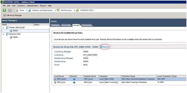
Enabling replication for TrueCopy Synchronous
Initiate Hitachi TrueCopy Synchronous replication from the horcm0 instance by typing the following at a command prompt in
the C:\HORCM\etc directory:
paircreate.exe –g  -vl –fg   –IH

Figure 15 shows the command and the output of a TrueCopy pair creation based on the HORCM configuration files in " Hitachi
TrueCopy Remote Replication Bundle Files."

Figure 15 – Pairdisplay output showing copy status of TrueCopy pair during paircreate

Enabling replication for Universal Replicator
Initiate Hitachi Universal Replicator replication from the horcm0 instance by typing the following at a command prompt in the
C:\HORCM\etc directory:
paircreate.exe –g  -vl –f async –jp  –js  –IH

Figure 16 shows the command and the output of a Universal Replicator pair creation based on the HORCM configuration files
in "Hitachi Universal Replicator Files."

Figure 16 - Pairdisplay output showing copy status of HUR pair during paircreate

(Optional) Enabling replication for ShadowImage
Initiate Hitachi ShadowImage replication from the horcm1 instance by typing the following at a command prompt in the
C:\HORCM\etc directory:
paircreate.exe –g  -vl -IM

Figure 17 shows the command and the output of a ShadowImage pair creation based on the HORCM configuration files in
"Hitachi ShadowImage Heterogeneous Replication Files."

Figure 17 - Pairdisplay output showing copy status of ShadowImage pair during paircreate

Configure Storage Replication Adapter with VMware Site Recovery Manager
With VMware Site Recovery Manager and Hitachi Storage Replication Adapter installed on virtual machines at both sites and
storage replication enabled, manage the disaster recovery workflow through the vSphere client. The following procedure
assumes the installation of the Site Recovery Manager plug-in with the vSphere client and the pairing of the protected and
recovery site vCenters.

To configure storage replication with your Site Recovery Manager environment, follow these steps:

1    From the Site Recovery Manager Management window, click Array Managers.

24
You can also read