Design and Performance Assessment of a Small-Scale Ferrite-PM Flux Reversal Wind Generator - MDPI
←
→
Page content transcription
If your browser does not render page correctly, please read the page content below
Article

Design and Performance Assessment of a Small-Scale
Ferrite-PM Flux Reversal Wind Generator
Bharathi Manne 1,*, Malligunta Kiran Kumar 1 and Udochukwu B. Akuru 2,3,*
 1 Electrical and Electronic Engineering, Koneru Lakshmaiah Educational Foundation, Guntur 522502, India;
 mkkumar@kluniversity.in
 2 Department of Electrical Engineering, Tshwane University of Technology, Pretoria 0183, South Africa

 3 Department of Electrical Engineering, University of Nigeria, Nsukka, Enugu State 410001, Nigeria

 * Correspondence: bharathi.manne1994@gmail.com (B.M.); akuruub@tut.ac.za (U.B.A.);
 Tel.: +91-70-755-50797 (M.B.)

 Received: 4 September 2020; Accepted: 29 September 2020; Published: 23 October 2020

 Abstract: Currently, there is increasing research interest in harnessing wind energy for power
 generation by means of non-conventional electrical machines e.g., flux-reversal machines. The flux
 reversal machine is usually designed using scarce rare–earth permanent magnet material which
 may be unattractive in terms of machine cost. In this study, an attempt is made to re-design the flux
 reversal machine with non-rare-earth ferrite permanent magnet for wind energy applications.
 Because these machines possess high cogging torque, which results in vibration and noise, that are
 detrimental to the machine performance, especially at low speeds, a novel combined skewed and
 circumferential rotor pole pairing method is developed. The proposed cogging torque reduction
 method is implemented in 2-dimensional finite element analysis modeling and comparatively
 analyzed with other existing stand-alone methods viz., skewing, and rotor pole pairing. The results
 show that the proposed method led to 94.8% and 71% reduction in the cogging torque and torque
 ripple compared to the reference generator, respectively. However, the calculated torque density is
 reduced by 13%. Overall, the electromagnetic performance of the proposed ferrite PM machine
 exhibits desirable qualities as an alternative design for the direct drive wind generator.

 Keywords: cogging torque; ferrite PM; finite element analysis; flux reversal machine; non-rare earth;
 wind energy

1. Introduction
 The design of permanent magnet (PM) machines keeps growing significantly by the day due to
advantages of high-power density, high-efficiency, and torque density, useful for variable speed
drives in wind energy applications. The need for increased use of wind energy generation is well
established, due to its availability throughout the day and the possibility for large megawatt
generation. Globally, installed wind power capacity has grown exponentially in recent years as
shown in Figure 1, captured from the recently released Renewables 2020 Global Status Report
renewables figure [1]. Wind power generation cost and reliability are critical factors that have to be
considered in wind generator designs, and as such attention is usually focused in the direction of the
existing drive concepts [1]. The various wind generator drive concepts are high-speed (HS), medium-
speed (MS), and low-speed (LS) as characterized in Table 1 [2].
 PMs are classified into rare-earth (RE) and non-rare-earth (NRE) materials. In recent years, the
unaffordability of RE PM prices forced the electrical machine designers to focus on inexpensive NRE
materials like ferrite PMs and these materials are more desirable for the industry [3]. The trending
flux-reversal machine (FRM), which is a pre-dominantly PM type machine, has been reported in some

Energies 2020, 13, 5565; doi:10.3390/en13215565 www.mdpi.com/journal/energies
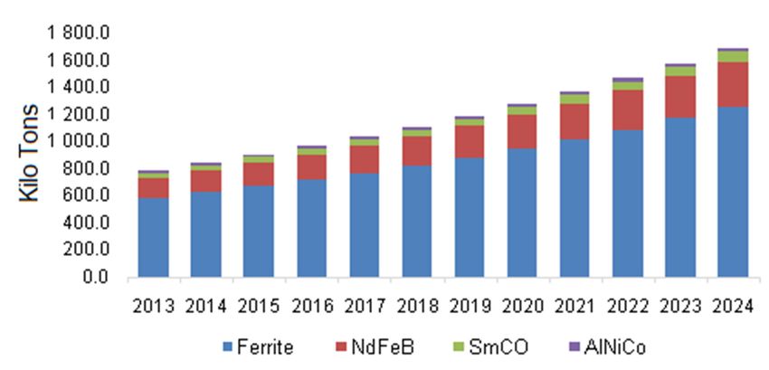
Energies 2020, 13, 5565 2 of 26

studies for rare-earth PM excited wind energy applications [4,5] and direct-drive drive-trains [6,7]. A
direct-driven wind turbine generator is important since it generates electricity through the wind
turbine drivetrain by eliminating the gearbox. The advantages of eliminating mechanical gearboxes
from the wind generator system include a reduction in the installation costs due to a lesser number
of components, lower energy costs due to a reduction in losses, and reduction in maintenance costs
due to the simplistic design [6].
 Depending on the variation in the rated speed of the wind turbine, direct drive is in the range of
120–500 r/min, with a corresponding generator power range of 0.5–3 KW [6]. The conventional
synchronous and induction generators are not suitable for LS and MS applications [7]. The majority
of LS and MS applications are handled by mechanical drives (mechanical gear and high-speed
motor). For LS, existing generators require a large number of stator slots and poles, resulting in a
machine with a large air-gap diameter [7].
 Meanwhile, ferrite PM materials offer less expensive PM options for machine design but are
more demagnetization prone due to the low coercivity compared to RE PM materials [8]. The
affordability of NRE materials is mainly due to its availability as shown in Figure 2 [9].

 Figure 1. Global total installed capacity [1].

 Table 1. Characteristics of wind turbine drive-trains [2].

 Parameter HS MS LS
 Speed margin 600–2000 r/min 40–600 r/min 4–35 r/min *
 Mass Lightest Intermediate Heaviest
 Size Smallest Intermediate Largest
 Gearbox presence Yes (3G ¤) Yes (1G/2G) Absent
 Generator type IG/SG § IG/SG SG
 Mechanical losses High Intermediate Lowest
 Electrical losses Lowest Intermediate Highest
 Cost Gearbox # Intermediate Generator #
 * Depends on operating power level. ¤ G represents the stage of the gearbox. § IG = induction generator,
 SG = synchronous generator. # highest cost.
Energies 2020, 13, 5565 3 of 26

 Figure 2. Global permanent magnet (PM) materials market capacity, 2013–2024 [9].

 The FRM machine belongs to the category of double salient permanent magnet (DSPM)
machines with PMs on the stator pole surface. Most of the PM machines employ interior rotor PM or
surface mounted rotor PMs. Here, in this PMs are in the rotating part, which may cause
demagnetization problems, limitations on mechanical instability, and poor thermal dissipation.
These structures are not favorable for HS and MS applications [10,11]. To this end, stator-mounted
permanent magnet (SMPM) machines were introduced, they are basically, flux switching machines
(FSM) and flux reversal machines (FRM). These machines generally have similar features such as easy
rotor structure, short winding terminals, good at thermal conditions [12]. FSM as a single-phase flux
switch alternator and was introduced by Rauch and Johnson in 1955. It exhibited poor rotor volume
usage causing stator vibrations and difficulty in stator fabrication [13]. To overcome these difficulties
in the manufacturing process and to improve the torque (power) density, Deodhar et al. introduced
single-phase FRM in 1997 for automobile applications to replace standard claw pole alternator [14,15].
 The basic 3-phase FRM of 6/8 slot-pole combination with concentrated winding was introduced
by Wang et al. [16,17]. In this machine, the design was optimized from single phase to 3-phase to
ensure maximum PM flux-linkages in the stator winding, lighter PM, and low cogging torque (CT).
However, this type of PM machines exhibit high torque ripple and lead to vibration and noise. The
main cause of the torque ripple is the cogging torque (CT). The CT is mainly position-dependent and
load-independent torque, caused due to the PMs, it mainly deteriorates the machine performance
especially at LS and MS. More and more researchers dedicated themselves to suppress the CT in RE
FRM while maintaining all other machine performances [18–22]. As seen from the literature, the CT
reduction in the FRM plays major role in-terms of ripple-torque. Most of the CT minimization
methods for FRM, published in the literature are some auxiliary techniques like notching, pole
pairing, and skewing [18–21]. These techniques may be limited for the FRM as nothing serious has
been reported for NRE variants. Besides, FRM requires less number of stator slots and a large number
of rotor poles, which qualifies them for direct-driven wind energy generators [5,7].
 The main contribution of this paper is to reduce the cogging torque and torque ripple by a
combination of techniques in the proposed ferrite PM FRM while maintaining respectable
electromagnetic performance compared to the basic machine as necessary for direct-drive wind
generator applications. Thus, an overview of the FRM technology including working principle,
machine capabilities using a flux-mmf diagram (FMDT), as well as design features based on different
RE topologies, are discussed in Section 2. In Section 3, the finite element analyses (FEA) on two
existing stand-alone cogging torque minimization methods, as well as the novel method combining
these two methods are undertaken. The power generating performance of all the four generators
considered in this paper in terms of output voltage, power density, voltage regulation, efficiency at
the rated condition, and overload/speed capabilities are discussed and compared by FEA. In Section
4, some concluding remarks are given.
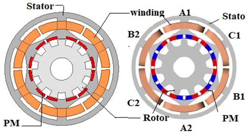
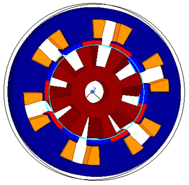
Energies 2020, 13, 5565 4 of 26

2. Overview of RE-PM FRMs

2.1. Structure and Configuration of RE-PM FRM
 An early example of 6/4 pole double salient non-rotating PM type motor whose PMs are installed
in the stator yoke is illustrated in Figure 3. This double salient structure enables the superior
performance of torque production, small frame sizes and qualifies the motor as a potential alternative
to existing servo drives, variable speed drives, as well as for satisfying the increasing demand in
future automobiles. The experimental test results have been encouraging, demonstrating twice the
output capability, with higher efficiency and power density when compared with the induction
motor [11]. A new brushless double-salient 2/3 pole FRM, as depicted in Figure 4, is designed,
analyzed, and fabricated based on a single-phase prototype machine for high-speed generator. FMDT
is employed to analyze the qualitative performance of FRM with other types of brushless machines
[15].

 Figure 3. 3-phase, six/four-pole double salient permanent magnet (DSPM) machine [11].

 Figure 4. 1-phase, two/three-pole stator-PM generator [15].

 Three-phase 6/8 FRM has been introduced by Wang as depicted in Figure 5, where the magnetic
field distribution, self and mutual inductances, cogging torque variations with rotor positions are
analyzed through 2D FEA [16,17]. In addition, 2-phase, 3-phase, and 5-phase pole combinations with
suitable rotor skewing techniques are documented to minimize the cogging torque. The machine
capabilities in terms of low rotor inertia, low electrical time constant, and high torque density, as
proven by FEA, had been discussed.
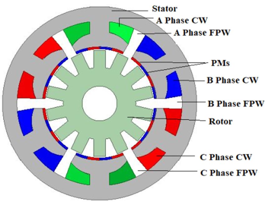
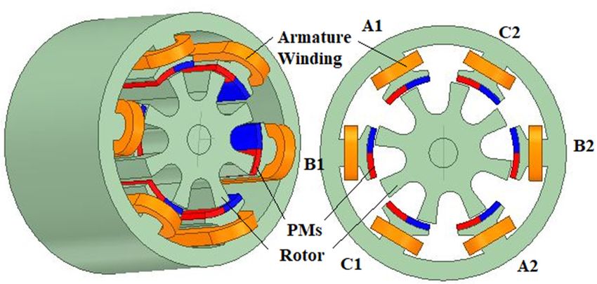
Energies 2020, 13, 5565 5 of 26

 Figure 5. 3-phase, eight/six-pole flux-reversal machine (FRM) [16,17].

 Another example of FRM for the servo drive application is depicted in Figure 6 with 12/28 poles
[23]. The design specifications and operation of FRM for low-speed, high-torque applications are
explained in [23]. The inset type PM structure is proposed to reduce the flux fringing of 12/40 pole
FRM for servo drives (LS). Through FEA, it is shown that this configuration has achieved high
efficiency, high torque density, and less than 3% torque ripple with three-phase sinusoidal vector
control. Already, the candidature of the FRM for wind applications is growing as shown by some
studies [24,25]. A 3-phase, 6/14 pole, 2.4 kW, 214 r/min outer rotor FRM has been introduced by D. S.
More [24]. Through experimentation, it is concluded that inner rotor FRM has 1.25 times lower power
density than outer rotor FRM. These two types of machines are depicted in Figures 7 and 8. Power
density comparisons have been made in [25]. Compared with other types of DSPM, it is found that
FRM has higher power density [5] for fractional-slot concentrated winding (FSCW) of FRM and
permanent magnet synchronous machine (PMSM). Through experimentation, it is found that FRM
has 1.5 times higher power density. Both the machine efficiencies are approximately the same [25].
To further improve the power density of FRM, a full-pitched winding (FPW) is incorporated in the
stator of the FRM as shown in Figure 9 [26].

 (a) (b)
 Figure 6. Various pole and PM arrangements of the FRM machines [23]; (a) PMs on stator pole; (b)
 inset PMs on stator.
Energies 2020, 13, 5565 6 of 26

 Figure 7. A typical 3D Structural view of 6/14 inner pole rotor of FRM [24].

 Figure 8. Cross-section of 3phase, 6/14 outer pole rotor FRM [24].

 Figure 9. Structural-view of 6/14 FRM [25,26]; FPW: Full-pitched winding, CW: Concentrated winding.

 Comparing different topologies of the FRM, that is, the consequent-pole permanent magnet
(CPM) topology with the SMPM topology, as illustrated in Figure 10, it was concluded that CPM
topology improves the torque performance and reduces the magnetic volume [27]. To reduce the cost
of PMs, consequent-pole transverse-flux permanent magnet linear machine (TFPMLM) is proposed,
partially replacing PM Poles by soft magnetic iron in [27,28].
 Introducing a small space-gap between the adjacent PMs belonging to the same stator pole shoe,
as illustrated in Figure 11, has helped to improve the phase back-emf and cogging torque [29]. FRM
designed with soft magnetic composite materials for fans exhibited a significant increase in efficiency
while producing high power density and reducing the usage of PMs compared to the existing PM
type machines [30]. Based on electromagnetic compatibility, high-speed FRM topology has been
proposed for the angular grinder as shown in Figure 12 and experimental results show that the
Energies 2020, 13, 5565 7 of 26

efficiency of the developed machine is higher than that produced in induction and brushless type
motors [31].

 (a) (b)
 Figure 10. Typical topologies of FRM: (a) consequent-pole permanent magnet (CPM)-FRM); (b) stator-
 mounted permanent magnet (SMPM)-FRM [27,28].

 Figure 11. 3-phase, 6-stator-pole/8-rotor-pole FRM [29].

 Figure 12. Cross-section of 1-phase, FRM motor [31].

 Comparisons with the different configurations of the FRM showed that the stator flux linkages
of the 6/14 FRM is doubled compared to that of the 12/16 pole FRM as illustrated in Figure 13 [32].
This is because in the 12/16 pole FRM, the stator teeth surface occupies around 2/3 of the inner stator
surface and 1/3 of the stator inner surface is wasted. Accordingly, it causes high cogging torque (CT),
vibrations, and acoustic noise. To overcome all the constructional issues of the 12/16 pole FRM,
Dmitrievskii introduced the inner stator surface 12/10 pole FRM in 2018 as shown in Figure 14 [32].
Acoustic noise and CT are further reduced by this configuration for wind applications.
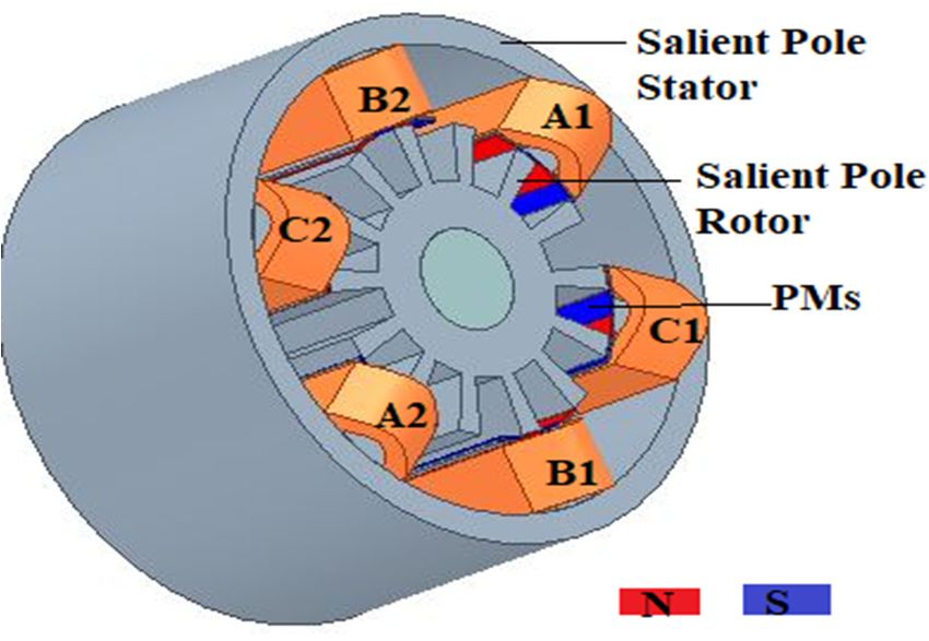
Energies 2020, 13, 5565 8 of 26

 A 3 kW, 200 r/min, 48/46 pole FRM has been projected for direct-drive wind energy [32] and is
depicted in Figure 15, FEA calculations are done for FRM and PMSM with the same machine
dimensions, power ratings, and speed. It is concluded that core volume is reduced by 25.6% and PMs
required for FRM is five times less than that for PMSM and correspondingly, the cost of the active
material like the PMs becomes twice as low as for PMSM. Then, the number of poles of FRM is higher,
the frequency of FRM is thrice as high at the same speed of both the machines, and hence FRM is best
suitable for variable speed applications than PMSM. The FRM cooling is simpler, and it can run at
higher ambient temperatures. The FRM efficiency is 2.3% higher than the PMSM for gearless wind
energy applications [31]. More [5,6] and Pellegrino [7] introduced fictitious electrical gear of 6/14 FRM
for direct drivetrains i.e., low-speed high torque applications. It is concluded with fabrication results
that FRM can be considered as PMSM with an inbuilt gearing effect [5,6]. The various design
parameters influencing FRM performance are also analyzed [7]. A new proposed FRM structure is
examined to improve the CT profile by changing the PM thickness and rotor side geometrical
parameters for wind generators [33].

 Figure 13. Schematic representation of 12-stator-slot/16-pole-rotor of FRM [32].

 Figure 14. Configuration of a 12-stator-slot/10-pole-rotor of FRM [32].
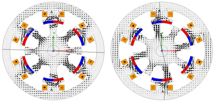
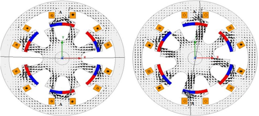
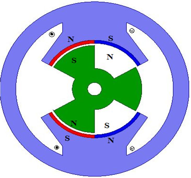
Energies 2020, 13, 5565 9 of 26

 Figure 15. 3-phase, 48/46-pole FRM generator for the direct drive [32].

2.2. Basic Principle, Design Topologies, and Performance of FRM
 FRMs are hybrid machines combining the advantages of a switched reluctance machine (SRM)
and DSPM into one machine. Both the rotor and stator poles have double salient structures. For this
non-conventional type of machine, the operational capabilities are analyzed by the flux-mmf diagram
technique (FMDT) and implemented using FEA by Ion Boldea in 1996 [14,15]. FMDT has its origin in
the ψ–I diagram and can predict the periodic variation of phase mmf and flux variations over an
electrical cycle. The FMDT for three double salient type machines for comparisons is illustrated in
Figure 16. The area enclosed by the flux-mmf loop is the average energy converted over an electrical
period and it specifies the average electro-magnetic torque produced over a rotor movement. From
this comparison, it is seen that the SRM has uni-polar mmf; phase-flux variations and energy
conversion loop are limited to the first quadrant only whereas the DSPM has bipolar mmf and uni-
polar phase-flux, with the energy conversion loop limited to two quadrants. However, the FRM has
bipolar mmf and phase-flux variation with respect to rotor movement, the energy conversion loop
covers the four quadrants; meaning that control is possible for all four quadrants. The typical 2D and
3D cross-section of FRM of 6/8 poles are illustrated in Figure 17. The flux and flux density distribution
in the machine at aligned and un-aligned positions of the rotor are illustrated in Figure 18. The
variation of mmf and phase-flux with respect to rotor displacement are shown in Figure 19. The
principle of FRM is variable flux linkages, inducing an emf that interacts with alternating armature
current as seen in Figure 18. The ideal variation of mmf and phase flux with respect to the rotor
displacement is seen in Figure 19. The field excitation provided by the PMs, armature winding flux
linkages are modulated by the variation of the magnetic circuit reluctance, as rotor displaces, in such
a way that bipolar induced emf are produced without rotating the PMs [15].

 Figure 16. Comparisons with three double salient type machines [14].
Energies 2020, 13, 5565 10 of 26

 Figure 17. A typical 3D and 2D structures of designed FRM.

 (a) (b)

 (c) (d)
 Figure 18. Flux-distribution of six/eight-pole FRM: (a) rotor position at 0 ; (b) rotor position at 11.25
 ACWD; (c) rotor position 22.5 ACWD; (d) rotor position at 11.25 CWD.

 Figure 19. Variation of mmf and phase-flux variations with respect to rotor displacement [15].

 In the generator case, when the rotor is driven by the prime mover as in Figure 18a, the
equilibrium position of the rotor poles show they are unaligned with stator poles. At that position,
there are no flux linkages with the coils. Only the flux setup by the magnets circulates completely
within each stator teeth (point “a” in Figure 19). In Figure 18b, the rotor is driven to 11.25 in an
anti-clockwise direction (ACWD) then the rotor poles overlap with the stator pole magnets and flux
creates the path from upper PMs, lower PMs, and stator back core iron. Phase flux is extreme in this
position at (point “b” in Figure 19). In Figure 18c, again at equilibrium position which is displaced
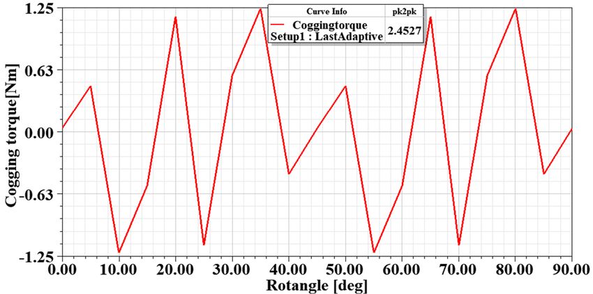
Energies 2020, 13, 5565 11 of 26

from the first equilibrium position by 22.5 no flux links with the coils (point “c” in Figure 19).
Further movement of the rotor leads to the position in Figure 18d of 11.25 clockwise direction
(CWD), where phase flux is again extreme in the opposite direction to that of the first alignment
position (point “d” in Figure 19). Linear bipolar phase flux variation induces a total induced emf, e .
According to the Faraday’s law of electromagnetic induction (1), a change in flux linkage produced
by ψ (field source), at a given electrical speed ω in rad/s, the emf induced e is given as
 dψ
 e = −ω (1)
 dθ
 Table 2 shows the evaluated dimensions of a FRM through the sizing equation technique [23].
Based on these dimensions, FRM has been analyzed in 2D FEA and by using the magneto-static solver
analyzed the flux density distribution and cogging torque. The meshed plot and no-load flux-density
distribution of the modeled machine are shown in Figure 20. The magneto-static cogging torque is
shown in Figure 21. It is important to note that FRM exhibits fault tolerance ability because the mutual
inductance magnitude value is less than one-fiftieth of the self-inductance of the phases which
indicates that natural isolation between the phases. The variation of the inductances with respect to
the rotor displacement is small. Here the mutual inductance 4 mH and self-inductance is 0.61 H.
Therefore, the reluctance torque is insignificant.

 (a) (b)
 Figure 20. FEA evaluation of no-load behavior of FRM: (a) mesh plot; (b) flux density map.

 Table 2. Dimensional details of non-rare-earth (NRE) FRM.

 S. No Parameters Value Symbol
 magnet thickness 3 mm hpm
 stator-pole span angle 42.6 βs
 stator-pole height 15 mm hps
 outer diameter of stator 129 Ds
 Stator stator arc span 27.8 mm τps
 stack length 400 mm lstk
 no. of turns/coil 176 Nph
 air gap 0.5 mm g
 magnet remanence 0.4T (Sr-Fe) 0.4T (Sr-Fe)
 outer diameter of rotor 72 mm Dr
 Rotor rotor arc span 12.3 mm τpr
 rotor pole span angle 21 βr
 rotor pole height 17 mm hpr
Energies 2020, 13, 5565 12 of 26

 Figure 21. Cogging torque cycle under magneto-static no-load (MSNL).

2.3. Design Topologies
 A general rule regarding the number of rotor poles N and the number of stator poles N and
choosing “p” for the number of phases of FRM is [17]:
 N p
 = (2)
 N p 1
 Hence N ⁄N = 3/4, 6/8, 12/16, etc., are prevalent for 3-phase FRM machines (2).
 If a number of pairs of PMs are given, then [23]:
 n 1
 N =N (3)
 3
where np = number of PMs pair poles. Various possible configurations of the FRM are shown in Table
3. For 6/8 FRM configuration accompanied one pair of PMs in each stator pole (3). The no-load flux
density plot of 6/8 pole FRM is illustrated in Figure 20. In addition, the number of possible PMs on
the stator surface and the number of effective poles corresponding to the flux patterns are given in
Table 3. Table 3 shows that as the number of rotor poles increases, speed decreases. Increasing the
rotor pole number means increasing the energy cycles per revolution. Thus, the reluctance torque is
negligibly small, even though the CT is still slightly high for LS applications. With the proper design
and control, the cogging torque component can be made relatively small. The number of poles
corresponding to the effective flux patterns, speed, and gear ratio for different FRM topologies for LS
applications are given in Table 3. A summary of the various FRM topologies highlighted so far is
evaluated from ten points of view with reference to wind turbines in Table 4. The performance marks
are given in a percentage scale. In Table 4, these percentage values are represented in form of their
fractional values.

 Table 3. Various possible configurations of PM FRM.

 Machine Number of Effective Number of Speed for 50 Cogging
 Type Flux Patterns Magnets Hz (r/min) Torque Cycle
 6/8 2 12 375 15
 6/14 2 24 214 8.57
 12/16 4 24 188 7.5
 12/10 4 24 300 6.0
 12/28 4 48 108 4.2
 12/40 4 60 75 3.0
 48/46 4 96 65.3 0.33
Energies 2020, 13, 5565 13 of 26

 Table 4. Comparisons of various topology rare-earth (RE)-PM FRMs for wind energy applications.

 Figure
 Figure Figure 5 Figure Figure Figure Figure Figure 9 Figure 10a Figure Figure Figure Figure Figure
 Properties 10b
 4 [15] [16,17] 6a [23] 6b [23] 7 [24] 8 [24] [25,26] [27,28] 11 [29] 12 [31] 13 [32] 14 [32] 15 [32]
 [27,28]
 Constructional simplicity 1 1 1 0.8 0.8 0.6 0.4 0.4 0.4 0.8 0.1 0.8 0.8 0.6
 Power Density 0.6 0.8 0.8 0.8 0.8 1 1 0.8 1 0.8 0.6 0.6 0.8 0.8

 Usage of Rotor Volume 0.8 0.8 0.8 0.6 0.8 0.8 0.6 0.8 1 0.8 0.8 0.4 0.8 1

 Low material&
 1 0.8 0.6 0.4 0.8 0.6 0.6 0.4 0.4 0.8 1 0.6 0.6 0.6
 manufacturing cost
 Low CT 0.8 0.8 0.6 0.6 0.8 0.8 0.8 0.6 0.6 0.8 0.8 0.4 0.4 0.6
 High Temperature
 0.8 0.8 0.8 0.6 0.8 0.8 0.8 0.8 1 0.8 0.8 0.6 0.6 0.8
 operation
 Fault tolerance 1 0.8 0.8 0.6 0.8 0.8 0.8 1 0.8 1 0.6 0.6 0.8 0.8
 Easy replacement of
 0.8 0.8 0.6 0.6 0.8 0.6 0.6 0.8 0.8 0.8 0.6 0.6 0.8 0.6
 faulted coils
 Mechanical rigidity 0.8 0.8 0.6 0.6 0.8 0.6 0.8 0.6 0.6 0.8 0.6 0.6 0.6 0.8
 Flux Leakage 0.8 0.8 0.6 1 0.8 0.8 0.8 0.8 0.8 0.8 0.6 0.6 0.6 1
Energies 2020, 13, 5565 14 of 26

3. Analytical Calculation of Cogging Torque and Torque Ripple
 The 2-dimensional governing expression of PM FRM can be expressed in magnetic vector potential A
as [34]:
 ∂ 1 ∂A ∂ 1 ∂A ∂M ∂M
 + = −J − − (4)
 ∂x μ ∂x ∂y μ ∂y ∂x ∂y
where A = vector potential in z, J = current density, M = magnetization of PM.
 The flux linkage λ are calculated per phase from the average vector potential ‘A’ (4) over each winding
cross-section as

 ds ds
 λ= A − A l (5)
 s s

where l is stack length; s and s are the total area of Nph-turns per phase with the winding carrying
the negative and positive currents, respectively. The flux linkages of each phase of 3-phase FRM machines
can be evaluated (5).
 FRM mainly suffers from unfavorably large CT due to its double-salient construction and PMs,
resulting in undesirable vibration and noise especially for LS and MS wind energy applications. At high
speed, this effect is negligible [18]. The CT does not add to the average electro-magnetic torque, but only
affects the pulsations in the torque. It is also known as self-aligning torque or no-current torque. It occurs
mainly in PM machines. It is the torque due to the interaction between the PM and the stator slots. When
there is no current in stator windings, as the saliency nature of rotor and stator with uneven permeance in
the air gap produces the cogging torque [18]. The no-load open-circuit flux density distribution is obtained
from Equation (6), based on the mmf-permeance model in the airgap [19,20].
 B α, θ = F α ∧ α, θ (6)
where ∧ (α, θ) and F (α) are permeance in the air gap and the mmf excited by PMs, respectively. α is
the rotor position along the air gap circumference, θ is rotor position, w is the total energy stored in the air
gap and υ is the volume of the air-gap.
 The analytical expression of CT of FRM machines can be obtained [20] from the instantaneous torque
for every cycle of rotor displacement by means of the rate of change of co-energy with respect to the rotor
movement as shown in Equation (7).
 The 2D FEA is used to predict the overall CT as

 ∂w ∂ 1
 T =− =− B (α, θ) dυ
 ∂θ ∂θ 2μ
 (7)
 ∂ 1
 = F (θ) ∧ (α, θ)dυ
 ∂θ 2μ

 The cogging torque is calculated when the machine is at a standstill position and when there is no
current in the coils of the stator (i = 0). It is supposed that each section plane along axial direction has the
same magnetic field distribution (6). The cogging torque of FRM is obtained by having the calculated value
multiplied by the total machine length or stack-length [18]. The overall cogging torque mainly depends on
airgap permeance and PMs mmf functions (7).
 The analytical expression of total cogging torque for conventional stator active PM brushless FRM can
be expressed as [20]:

 ( − )
 = ( ⁄ ) ∧ ( ) (8)
 4
Energies 2020, 13, 5565 15 of 26

where = effective stack length, and are the outer rotor radius and inner stator radius, ∧ is
Fourier coefficient, and m is satisfied as the following expression is given as

 = ( )
 k =1,2,3….. (9)
 ,

where ( , ) is the highest common factor of and . The Equations (8) and (9) can be
appropriate for FRMs of any slot-pole configurations [20].
 The torque ripple factor krp is evaluated as

 T −T
 k = × 100 % (10)
 T

3.1. Cogging Torque Reduction Techniques for PM FRM
 Many researchers studied and developed different design techniques to minimize the CT of PM
machine structures [19]. The most accepted techniques to minimize CT is to optimally vary the dimensions
of the machine design such as rotor skewing, rotor teeth pairing, chamfering the rotor and stator PM
thickness, and rotor geometrical modifications. Generally, stator side modifications consist of tooth pairing,
magnet skewing, slot shifting, and dummy slots [35,36]. The stator side modifications augment the machine
size and cost. Thus, the stator modifications are not practical in the case of PM machines. Then, the rotor
side modifications are skewing rotor, chamfering, and radial pole pairing, and axial pole pairing [18–20].
The required modifications in the rotor than in the stator are generally used for minimizing cogging torque.
Therefore, in this paper, the analysis part is divided into three subsections, where the first and second are
used to report analysis of the existing CT minimization techniques like skewing and rotor pole pairing
(CPOP). In the third subsection, a novel model constituting, the combining of these two existing techniques
(SKCpp) is additionally investigated. Compared are different methods for electromagnetic performances of
a generator with various rotor side design modifications.

3.1.1. Skew Rotor Design
 Skewing is the most renowned and widely used technique to minimize the CT effects in PM machines.
Skewing can be done in either stator or rotor. In the FRM, the stator has magnets while the rotor is composed
entirely of laminations. So, rotor skewing is more feasible. Furthermore, when the rotor is skewed with the
optimal skewing angle, the CT is effectively minimized. The skewed rotor yields even permeance in
between the stator and rotor irrespective of the rotor displacement [17]. In this study, slicing or stepped
skew technique has been incorporated into the rotor structure and the rotor is sliced into five segments
along the length. For various skew angles (5 , 10 , 15 , and 20 ), the CT effect is analyzed by 2D FEA as
shown in Figure 22. The CT variation with rotor position has a cycle of 2 ⁄ . The CT cycle is 15 , which
agrees with FEA simulation as in Figure 22. Based on the simulation 15 skew angle effectively minimized
the CT compared with the other angles. FEA shows that the CT is decreased by 92.2%. Nevertheless, this
method leads to some reduction of flux linkages, induced emf, and the corresponding reduction of power
density.
Energies 2020, 13, 5565 16 of 26

 Figure 22. The effect of cogging torque for various skew angles.

3.1.2. Circumferential Rotor Teeth Pairing (βr) method or Rotor Pole Pairing (CPOP)
 The rotor teeth pairing method is also considered to minimize the CT of FRM. The CT waveform varies
with the rotor tooth width βr. This method of circumferential or rotor teeth pairing method employs two
different pole widths in the rotor design that can be applied. The variable magnetic reluctance of the rotor
and the air gap minimizes the amplitude of the CT. Based on the Fourier series expansion [18,20], by
adjusting the rotor pole width with respect to the PM width with these combinations the optimal rotor tooth
width has to be selected as 19 and 21 . The rotor poles are designed into two different pole arc widths,
these two arcs are oppositely employed as illustrated in Figure 23. The overall cogging torque got reduced
as verified by FEA. This technique reduced the CT by 14% of the original value in transient no-load. The
overall CT can also be minimized.

 Figure 23. Cross-section of teeth paired rotor.

3.1.3. Combined Auxiliary Model of FRM
 The skewing and rotor pole pairing methods are explained above; this paper attempts to combine these
two methods to obtain the performance of FRM better than any one of the two. This combined method is
the possible combinations of more than two existing CT reduction methods. There are various combined
methods are studied for PM machines. For example, the combination of rotor magnet skewing with teeth
notching by B. Zhang [21] and the combined pole and slot number by F. Yusivar [37]. The 3D structural
view of SKCpp is depicted in Figure 24. This method of combining the existing two methods is a novel
Energies 2020, 13, 5565 17 of 26

method and is being introduced for the first time. By this method, the CT is reduced by 94.8% of the original
value in Transient (TR) no-load by 2D FEA. Compared to the conventional skewing, rotor teeth-pairing, the
SKCpp also effectively minimized the cogging torque while maintaining all other electromagnetic
performances as in the basic model.

 Figure 24. 3D Structural view of SKCpp.

3.2. Basic Performance Evaluation
 Some evaluations are carried out to examine the generator performances for each rotor design in terms
of flux linkages, induced voltages, and cogging torque.

3.2.1. Flux Linkage
 Under the open-circuit condition, the flux from PMs is investigated with Equation (5). A 180 rotation
of the rotor, with step time as 0.1 ms and simulated time of 80 ms results in four cycles of 50 Hz frequency
and 800 simulations. Figure 25 clearly shows that CPOP has the highest flux-linkages amplitude that
emerges from the PM compared to other generators, while skew has the lowest flux linkage compared to
the other generators. For basic, skew, CPOP, and combined auxiliary models (SKCpp), the measured
maximum flux linkages are 0.41 Wb, 0.327 Wb, 0.433 Wb, and 0.348 Wb, respectively.

 Figure 25. Flux linkage waveforms comparison.
Energies 2020, 13, 5565 18 of 26

3.2.2. Induced Voltage
 Further, under open circuit condition (TR-no-load), the rotor is rotating at a prescribed speed of 375
r/min. The induced emfs of the four-rotor designs are analyzed and compared in Figure 26. As expected,
the highest magnitude is measured with CPOP as 118.4 V followed by basic, SKCpp and skewing with 112
V, 109.5 V, and 101.7 V, respectively.

 Figure 26. Induced voltage waveforms comparison at transient no-load.

3.2.3. Cogging Torque (CT) Reduction
 The CT as applied to PM machines is the torque effort due to magnets only viz., no load current present.
The CT leads to poor position control, vibration, noise, and reduction in generator performance. By setting
rotor speed at 375 r/min, and one complete electrical cycle of 180 , CT for various rotor configurations is
plotted as shown in Figure 27. This shows the conventional (basic) rotor model has the highest peak-to-peak
CT value of 1.82 Nm followed by the values for skewed, rotor teeth pairing (CPOP) and SKCpp models as
0.14 Nm, 1.56 Nm, and 0.09 Nm, respectively. As compared to the basic model, skew and SKCpp gives that
highest CT reduction. In Table 5, the reduction in CT at TR-no-load is compared quantitatively, which
indicates that the generator acoustic noise is lowest with proposed SKCpp.

 Figure 27. Comparisons of cogging torque effect for various methods at transient no-load.
Energies 2020, 13, 5565 19 of 26

 Table 5. Comparison table of reduction of CT for NRE PM FRM at TR-no-load.

 Rotor Model Cogging Torque (Nm) Cogging Torque Reduction (%)
 Conventional (6/8) 1.283 0
 Skew 0.1438 92.2
 CPOP 1.5625 14.5
 SKCpp 0.0940 94.8

3.2.4. Torque Ripple Reduction Analysis (TR-Load)
 The characteristics of the torque ripple lead to pulsating torque which results in noise and vibration,
impacting negatively on the machine performance under load. The torque ripple factor is evaluated by
Equation (10) and the torque ripple for different rotor modification techniques at the rated load is evaluated
as shown in Figure 28. It shows that the basic model has the highest torque ripple factor value of 18.6 %
followed by the values of skewing, CPOP, and SKCpp at 6.73%, 17.4%, and 5.5%, respectively. In comparison to
the basic model, the CPOP, and skew, the SKCpp model shows the highest torque-ripple reduction. In Table 6,
the reduction in torque ripple at TR-load is compared quantitatively with the conventional design as the
reference.

 Figure 28. Comparisons of a torque ripple effect for various methods at transient load.

 Table 6. Comparison table of reduction of torque ripple for NRE-PM FRM at TR-rated-load.

 Rotor Model Average Torque, Te (Nm) Torque Ripple Reduction (%)
 Conventional (6/8) 19.8537 0
 Skew 16.7142 64
 CPOP 21.1553 8
 SKCpp 18.419 71

3.3. Power Generating Performance Comparison
 The generating operating point performances including output voltage against load current, voltage
regulation, power curve in terms of varying load current and generator speed, as well as loss and efficiency
curves of the four generators working are analyzed by FEA simulation. The four generators are designed to
work under symmetrical resistive loads. Hence, based on the rated voltage of each phase and rated power,
the calculated rated load resistance, Rn, is 25.3 Ω.
Energies 2020, 13, 5565 20 of 26

 Figure 29 illustrates the variation curves of the output voltage versus phase current––so-called
overload capability curves––while the voltage regulation is presented in Figure 30. One can see from Figure
29 that the CPOP is presented with as the machine with the highest overload capability, while basic, SKCpp
and skew follow in that order. In Figure 30, as load current increases, the skew is presented with the highest
voltage regulation, followed by SKCpp, basic, and CPOP. Lower percentage values in Figure 30 is an
indication that there is a less voltage variation when the load changes in the generators.
 The generator load profiles are exhibited by varying the phase current against the output power for
each rotor design as shown in Figure 31. The overload limits are (4.6875 A, 850.77 W), (4.6875 A, 747.42 W),
(4.6875 A, 907.611 W) and (4.6875 A, 825.78 W) for basic, skew, CPOP, and SKCpp, respectively, which is
up to 1.5 times of the rated load. Meanwhile, the efficiencies are compared in Figure 32, for all generators.
 In terms of speed capability, the open circuit EMF increases with speed, which translates to increasing
power density. The speed capability of the generators are analyzed when connected with a symmetrical
rated load while varying the mechanical speed as shown in Figure 33. The output power of the skewed
rotor generator becomes easily saturated and decreases with the increase in the speed of the rotor. The core
loss and efficiency curves against rotor speed are also plotted as shown in Figures 34 and 35, respectively.
As expected, an increase in speed, increases the core-loss magnitudes. As the rotor speed increases, the core
losses become distinct and it is observed that SKCpp presents the lowest value compared with the other
generators.
 Overall, from the 2D transient FEA simulations, a summary of the performance for all four generator
designs is provided as shown in Table 7. It is interesting to note that the proposed SKCpp design yields
comparatively improved performance characteristics in terms of cogging torque and torque ripple
reduction, as well as efficiency, while CPOP presents better performance with respect to stability for
overload capability and voltage.

 Figure 29. Output voltage against phase current @ 375 r/min.
Energies 2020, 13, 5565 21 of 26

 Figure 30. Voltage-regulation against phase current (rms) for each rotor designs @ 375 r/min.

 Figure 31. Output-power against phase current (rms) for each rotor designs @ 375 r/min.

 Figure 32. Efficiency against phase current (rms) for each rotor designs @ 375 r/min.
Energies 2020, 13, 5565 22 of 26

 Figure 33. Output-power against mechanical speed (rpm) for each rotor design @ 375 r/min.

 Figure 34. Core-loss against rotor mechanical speed (rpm) for each rotor design @ 375 r/min.

 Figure 35. Efficiency against rotor mechanical speed (rpm) for each rotor design @ 375 r/min.
Energies 2020, 13, 5565 23 of 26

 Table 7. Comparison table of all the rotor designs of 6/8 NRE-PM FRM Generators.

 Cogging Power Voltage
 Rotor Model Torque Ripple Efficiency
 Torque Limit Regulation
 Basic (6/8) Poor Poor Moderate Moderate Good
 Skew Moderate Moderate Poor Poor Moderate
 CPOP Poor Poor Good Good Good
 SKCpp Good Good Moderate Moderate Good

4. Conclusions
 In this study, the possibility of using NRE (ferrite) PM excitations to design the flux reversal machine
for direct drive wind turbine generator has been demonstrated for the first time. Various existing RE PM-
FRM structures have been reviewed. In this frame of overview, fourteen RE PM FRM designs were
highlighted and examined in detail for their suitability for wind energy generation. The merits and demerits
of these FRM topologies were quantitatively deliberated in terms of power density, cogging torque, and
torque-ripple.
 Thereafter, a 6/8 pole ferrite PM FRM is redesigned with a conventional rotor model, as well as with
skewing and rotor pole pairing, while a new combination of skewing with circumferential rotor pole pairing
(SKCpp) is also designed and proposed for minimizing cogging torque and torque ripple. The machines are
numerically evaluated for wind power generation in 2D FEA. In addition, the generator performance, in
terms of flux linkages, induced voltages, over-load and over-speed capabilities, as well as efficiency, are
investigated and discussed. The results obtained through 2D FEA simulations show that the proposed
SKCpp technique as the best design approach for reducing the cogging torque and torque ripple effect in
ferrite PM FRM, with a percentage reduction of 94.8% at no-load and 71% under load, respectively.
However, the average torque is reduced by 13%. Overall, the potential of the proposed ferrite PM FRM for
wind power generation is clearly demonstrated for the reduction of cogging torque and torque ripple and
also for efficiency, overload, and speed regulation.

Author Contributions: Conceptualization, M.B. and U.B.A.; methodology, M.B. and U.B.A.; software, M.B.; validation,
M.B. and U.B.A.; formal analysis, M.B. and U.B.A.; investigation, M.B.; resources, M.K.K.; data curation, M.B.; writing—
original draft preparation, U.B.A. and M.B.; writing—review and editing, M.B., U.B.A. and M.K.K.; visualization, M.B.;
supervision, U.B.A. and M.K.K.; project administration, M.B.; funding acquisition, U.B.A. All authors have read and
agreed to the published version of the manuscript.

Funding: This research received no external funding but the APC is funded by Tshwane University of Technology,
South Africa.

Conflicts of Interest: The authors declare no conflict of interest.

Nomenclature
 Symbol Stands for
 e Induced EMF (V)
 ωe Electrical speed (rad/sec)
 hpm PM thickness (mm)
 τps Stator arc span (mm)
 hps Height of stator pole (mm)
 g Length of the airgap (mm)
 lstk Length of stack laminations (mm)
 Ds Outer diameter of stator (mm)
 hpr Height of rotor pole (mm)
 βr Span angle of rotor pole (o mech.)
 βs Span angle of stator pole (o mech.)
 Dr Outer diameter of rotor (mm)
 La Effective stator stack length
Energies 2020, 13, 5565 24 of 26

 Nph Number of turns per coil
 m Number of phases
 Nr Rotor pole number
 ψm The field source Flux linkage (Wb)
 Ns Stator pole number
 np Number of PMs Pairs
 Tcog Cogging torque (Nm)
 A Magnetic vector potential (T-m)
 J Current density per phase (A/mm2)
 M Magnetization of PMs (A/mm)
 τpr Rotor arc span (mm)
 λ Flux linkages per phase (Wb-t)
 o
 θ Position of the rotor ( mech.)
 w Magnetic co-energy (J)
 Fpm MMF due to Permanent magnets (A-t)
 B No-load flux density (T)
 ∧ Permeance (Wb/At)
 υ Air-gap volume (mm3)
 μo Permeability of free space (H/m)
 s Area of Nph turns
 R1 Outer rotor radius (mm)
 R2 Inner stator radius (mm)
 krp Ripple-torque factor (%)
 α Position along the circumference in the airgap
 Tmax Maximum Torque (Nm)
 Tmin Minimum Torque (Nm)
 Te Average Torque (Nm)

Abbreviations
 PM Permanent magnet
 RE Rare-earth
 NRE Non-rare earth
 HS High speed
 LS Low speed
 FRM Flux reversal machine
 FSM Flux switching machine
 SMPM Stator-mounted permanent magnet machine
 CT Cogging torque
 FMDT Flux-mmf diagram
 FEA Finite element analysis
 PMSM Permanent magnet synchronous machine
 FSCW Fractional slot concentrated winding
 FPW Full pitched winding
 CW Concentrated winding
 CPM Consequent-pole permanent magnet
 TFPMLM Transverse-flux permanent magnet linear machine
 SRM Switched reluctance machine
 DSPM Double salient permanent magnet machine
 TR Transient
 CWD Clockwise direction
 ACWD Anti-clockwise direction
 CPOP Circumferential rotor pole pairing
 SKCpp Skewing with circumferential pole pairing

References
Energies 2020, 13, 5565 25 of 26

1. REN 21. Renewables 2020 Global Status Report (Paris: REN21 Secretariat). Available online:
 http://www.ren21.net/gsr (accessed on 10 October 2020).
2. Akuru, U.B.; Kamper, M.J. Evaluation of flux switching PM machines for medium-speed wind generator drives.
 In Proceedings of the IEEE Energy Conversion Congress and Exposition (ECCE), Montreal, QC, Canada, 2015; pp.
 1925–1931.
3. Thomas, J. Getting rare-earth magnets out of EV traction machines: A review of the many approaches being
 pursued to minimize or eliminate rare-earth magnets from future EV drive trains. IEEE Electrif. Mag. 2017, 5, 6–18.
4. Arshad, S.; Selvi, V. 2D electromagnetic design of flux reversal generator for low speed wind applications using
 finite element analysis. Int. J. Eng. Technol. Sci. Res. 2017, 4, 149–157.
5. More, D.S.; Kalluru, H.; Fernandes, B.G. Comparative analysis of flux reversal machine with fractional slot
 concentrated winding PMSM. In Proceedings of the 34th Annual Conference of IEEE Industrial Electronics,
 Orlando, FL, USA, 10–13 November 2008; pp. 1131–1136.
6. More, D.S.; Fernandes, B.G. Analysis of flux-reversal machine based on fictitious electrical gear. IEEE Trans. Energy
 Convers. 2010, 25, 940–947.
7. Pellegrino, G.M.; Gerada, C. Modeling of flux reversal machines for direct drive applications. In Proceedings of
 the 14th European Conference on Power Electronics and Applications, Birmingham, UK, 30 August–1 September
 2011; pp. 10–18.
8. Akuru, U.B.; Kamper, M.J. Investigation of low-cost PM flux switching machine for medium speed geared wind
 energy application. In Proceedings of the 25th South African Universities Power Engineering Conference
 (SAUPEC), Stellenbosch, South Africa, 2017; pp. 613–618.
9. Akuru, U.B. Design Optimization and Performance Evaluation of Flux Switching Machines for Geared Medium-
 Speed Wind Generator Drives. In Proceedings of IEEE PES/IAS Power Africa Conference, Cape Town, South
 Africa, 2018; pp. 925–930.
10. Yuting, G.; Ronghai, Q.; Dawei, L.; Li, J. Torque performance analysis of three-phase flux reversal machines for
 electrical vehicle propulsion. In Proceedings of the 2016 IEEE Transportation Electrification Conference and Expo
 Asia-Pacific (ITEC Asia-Pacific), Busan, Korea, 1–4 June 2016; pp. 297–301.
11. Liao, Y.; Liang, F.; Lipo, T.A. A novel permanent magnet motor with doubly salient structure. IEEE Trans. Ind.
 Appl. 1995, 31, 1069–1078.
12. Jianzhong, Z.; Ming, C.; Zhe, C.; Wei, H. Comparison on stator-mounted permanent-magnet machines based on a
 general power equation. IEEE Trans. Energy Convers. 2009, 24, 826–834.
13. Rauch, S.E.; Johnson, L.J. Design principles of flux-switch alternators. IEEE Trans. Am. Inst. Electr. Eng. 1955, 74,
 1261–1268.
14. Deodhar, R.P. The Flux-MMF Diagram Technique and Its Applications in Analysis and Comparative Evaluation
 of Electrical Machines. Ph.D. Thesis, University of Glasgow, Glasgow, UK, October 1996.
15. Deodhar, R.P.; Andersson, S.; Boldea, I.; Miller, T.J.E. The flux reversal machine: A new brushless double-salient
 permanent magnet machine. IEEE Trans. Ind. Appl. 1997, 33, 925–934.
16. Wang, C.; Nasar, S.A.; Boldea, I. Vector control of three-phase flux reversal machine. Electr. Mach. Power Syst. 1999,
 28, 153–166.
17. Wang, C.; Nasar, S.A.; Boldea, I. Three phase flux reversal machine (FRM). IEE Proc. Electr. Power Appl. 1999, 146,
 139–146.
18. Zhao, W.Y.; Chen, Y.G.; Shen, Y.B.; Xing, S.Z. Effective methods of reducing cogging torque in flux-reversal
 machine. J. Iron Steel Res. Int. 2006, 13, 444–449.
19. Zhu, X.; Hua, W. An improved configuration for cogging torque reduction in flux-reversal permanent magnet
 machines. In Proceedings of the 2016 IEEE Conference on Electromagnetic Field Computation (CEFC), Miami, FL,
 USA, 13–16 November 2016; pp. 18–21.
20. Xiaofeng, Z.; Wei, H.; Zhongze, W. Cogging torque suppression in flux-reversal permanent magnet machines. IET
 Electr. Power Appl. 2018, 12, 135–143.
21. Zhang, B.; Wang, X.; Zhang, R.; Mou, X. Cogging torque reduction by combining teeth notching and rotor magnets
 skewing in PM BLDC with concentrated windings. In Proceedings of the 2008 International Conference on
 Electrical Machines and Systems, Wuhan, China, 17–20 October 2008; pp. 3189–3192.
22. Chu, W.Q.; Zhu, Z.Q. On-load cogging torque calculation in permanent magnet machines. IEEE Trans. Magn. 2013,
 49, 2982–2989.
Energies 2020, 13, 5565 26 of 26

23. Boldea, I.; Zhang, L.; Nasar, A. Theoretical characterization of flux reversal machines in low-speed servo drives-
 the pole-PM configuration. IEEE Trans. Ind. Appl. 2002, 38, 1549–1557.
24. More, D.S.; Kalluru, H.; Fernandes, B.G. Outer rotor flux reversal permanent magnet machine for rooftop wind
 generator. In Proceedings of the Industry Applications Society Annual Meeting 2008 IAS’ 08, Edmonton, AB,
 Canada, 25 April 2008; pp. 1–6.
25. More, D.S.; Fernandes, B.G. Power density improvement of three phase flux reversal with distributed winding.
 IET Electr. Power Appl. 2010, 4, 109–120.
26. More, D.S.; Fernandes, B.G. Novel three phase flux reversal machine with full pitch winding. In Proceedings of
 the 7th International Conference on Power Electronics, Daegu, Korea, 22–26 October 2007; pp. 1007–1012.
27. Yang, H.; Zhu, Z.Q.; Lin, H.; Li, H.Y.; Lyu, S. Analysis of consequent-pole flux reversal permanent magnet machine
 with biased flux modulation theory. IEEE Trans. Ind. Electron. 2020, 67, 2107–2121.
28. Luo, J.; Kou, B.; Zhang, H.; Qu, R. Development of a consequent pole transverse flux permanent magnet linear
 machine with passive secondary structure. CES Trans. Electr. Mach. Syst. 2019, 3, 39–44.
29. Zhu, X.; Hua, W. Back-EMF waveform optimization of flux-reversal permanent magnet machines. AIP Adv. 2017,
 7, 1–5.
30. Dmitrievskii, V.; Prakht, V.; Sarapulov, S.; Askerov, D. A multipole single-phase SMC flux reversal motor for fans.
 In Proceedings of the 2016 XXII International Conference on Electrical Machines (ICEM), Lausanne, Switzerland,
 4–7 September 2016; pp. 53–59.
31. Dmitrievskii, V.; Prakht, V.; Pozdeev, A.; Klimarev, V.; Mikhalitsyn, A. Angular grinder with new flux reversal
 motor. In Proceedings of the 2015 International Conference on Electrical Machines and Systems (ICEMS), Pattaya,
 Thailand, 25–28 October 2015; pp. 1366–1371.
32. Dmitrievskii, V.; Prakht, V. Gearless generator with magnets on the stator for wind turbine. In Proceedings of the
 Wind Europe Conference 2018, Hamburg, Germany, 25–28 September 2018; pp.1–8.
33. Vidhya, B.; Srinivas, K.N. Effect of stator PM thickness and rotor geometry modifications on the minimization of
 cogging torque of flux reversal machine. Turk. J. Electr. Eng. Comput. Sci. 2017, 25, 4907–4922.
34. Heoung, T.K.; Sung, H.W.; Bong, K.; Lee, J. Reduction of cogging torque in flux reversal machine by rotor teeth
 pairing. In Proceedings of the IEEE International Magnetics Conference (INTERMAG), Nagoya, Japan, 4–8 April
 2005; pp. 3964–3966.
35. Gyeong, C.L.; Jung, T.U. Cogging torque reduction design of dual stator radial flux permanent magnet generator
 for small wing turbine. In Proceedings of the IEEE 2013 Tencon-Spring, Sydney, NSW, Australia 17–19 April 2013;
 pp. 85–89.
36. Xu, W.; Zhu, J.; Zhang, Y.; Hu, J. Cogging torque reduction for radially laminated flux-switching permanent
 magnet machine with 12/14 poles. In Proceedings of the IECON 2011-37th Annual conference on IEEE Industrial
 Electronics Society, Melbourne, VIC, Australia, 7–10 November 2011; pp. 3590–3595.
37. Yusivar, F.; Roy, V.H.S.; Gunawan, R.; Halim, A. Cogging torque reduction with pole slot combination and notch.
 In Proceedings of the IEEE International Conference on Electrical Engineering and Computer Science, Kuta,
 Indonesia, 24–25 November 2014; pp. 260–263.

 Publisher’s Note: MDPI stays neutral with regard to jurisdictional claims in published maps and institutional
 affiliations.

 © 2020 by the authors. Licensee MDPI, Basel, Switzerland. This article is an open access
 article distributed under the terms and conditions of the Creative Commons Attribution
 (CC BY) license (http://creativecommons.org/licenses/by/4.0/).
You can also read